THE PHOTOGRAPHIC ARCHIVE
Additional photo review
Earlier experiments and more recent work, gathered in one place.
Project names, years, and descriptions are being added. Open a photograph for a closer look; its number stays the same wherever it appears.
229 photographs · click any photo to enlarge
Photos 246–251
Batch 01 · 4 photographs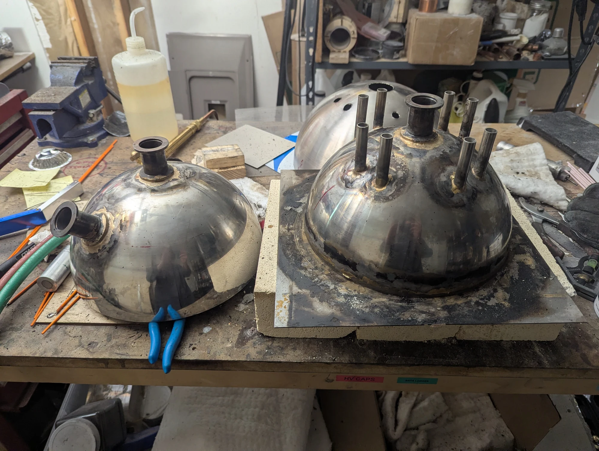
The latest iteration of my high-temperature vacuum furnace, shown during assembly. The stainless-steel hemispheres have feed-through tubes and KF25 vacuum connection flanges brazed onto their surfaces. Brazing joins metal parts using a melted filler metal.
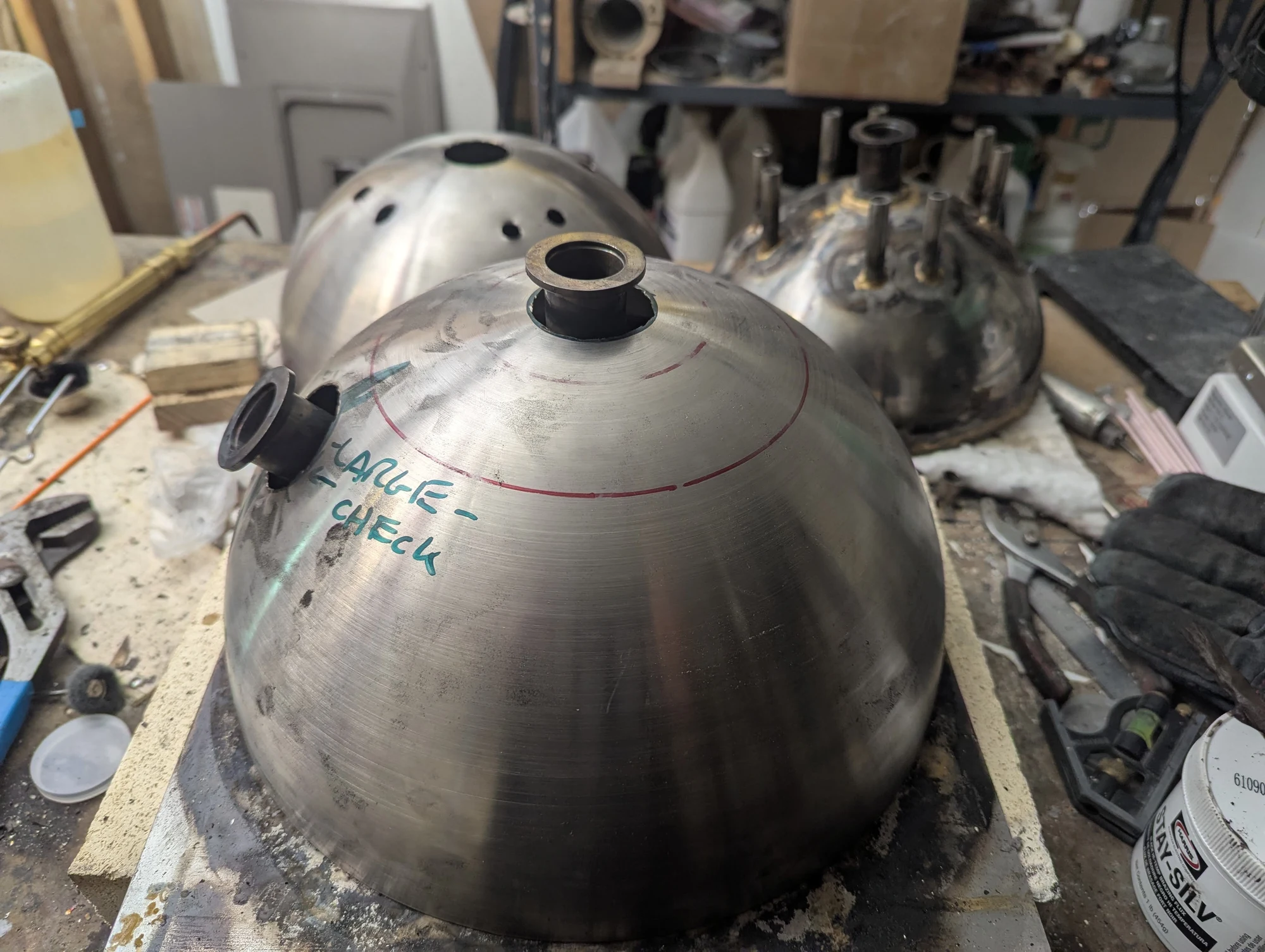
This stainless-steel hemisphere was intended to form a water jacket, carrying cooling water around the furnace. The thin steel warped too much during brazing, so I later replaced this part with a plastic version.
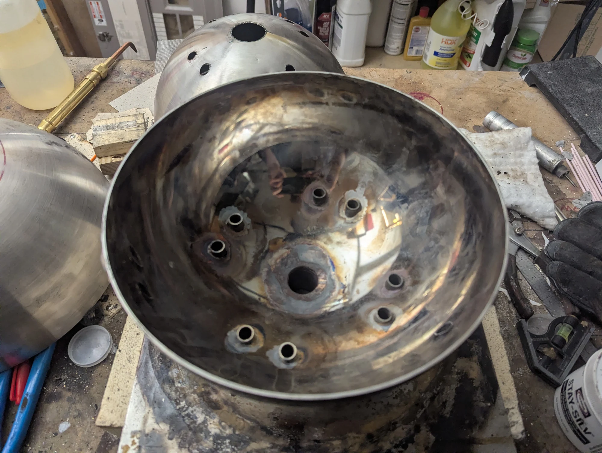
An inside view of the stainless-steel furnace hemisphere shown in Photo 246, revealing the openings and joints for the chamber fittings.
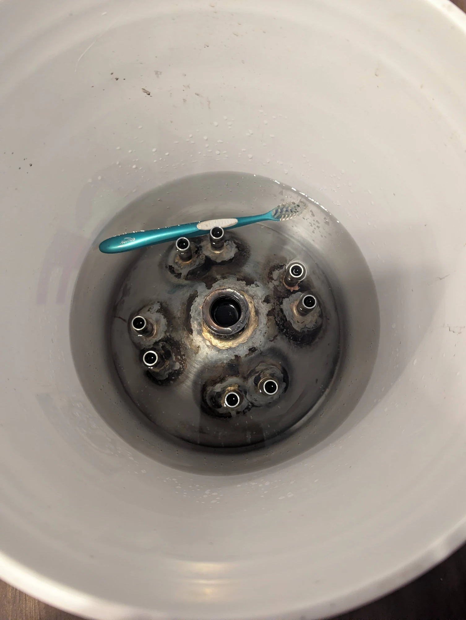
Cleaning flux residue from the stainless-steel hemispheres after brazing. Flux helps the metal-joining process, and its residue needs to be removed afterward.
Photos 252–253
Batch 02 · 2 photographs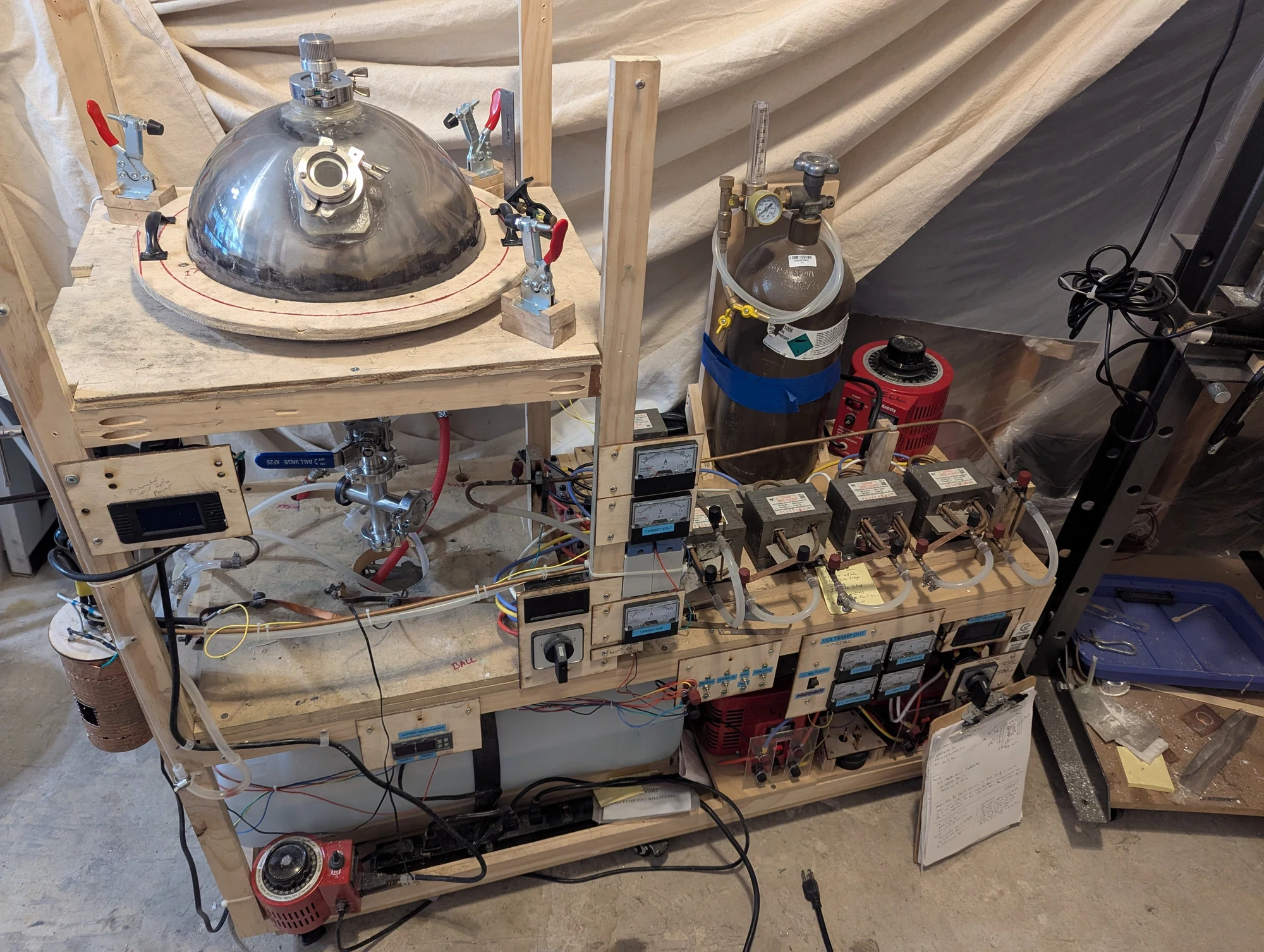
The vacuum furnace mounted on its support frame during assembly. The vacuum-system connections were not all attached at this stage.
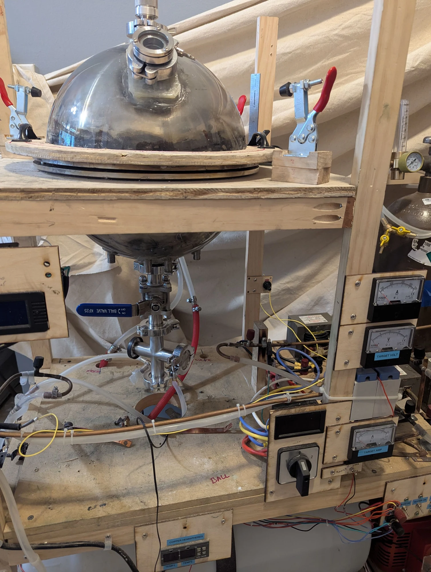
A second view of the furnace and its support frame while the vacuum system was still being assembled.
Photos 254–255
Batch 03 · 1 photographs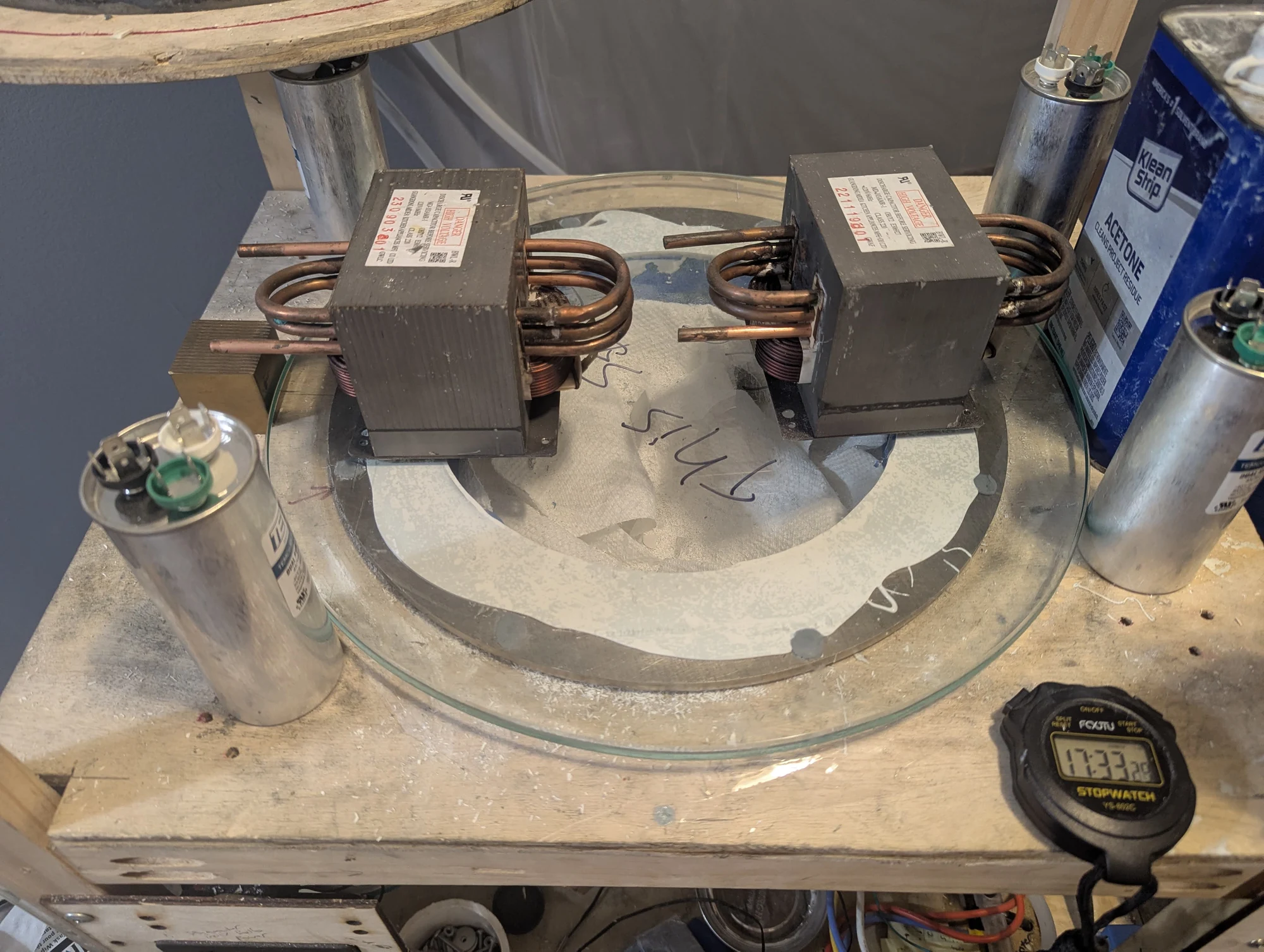
Brazing had warped the stainless-steel flange, preventing it from seating correctly. I built up the surface with low-outgassing epoxy, which releases little gas in a vacuum. A flat reference disc was used to transfer a flat surface to the epoxy.
Photos 256–362
Batch 04 · 90 photographs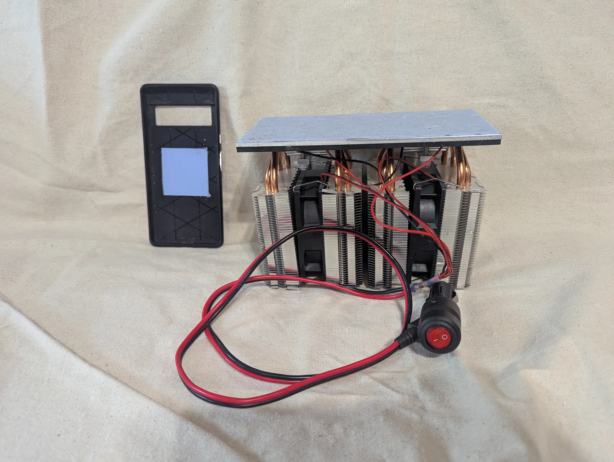
A prototype phone cooler using a thermoelectric module, which moves heat when powered by electricity. On the right is the cooler with a 12-volt car-power adapter. On the left, a cutout in the phone case holds a silicone thermal pad to help transfer heat from the phone to the cooler.
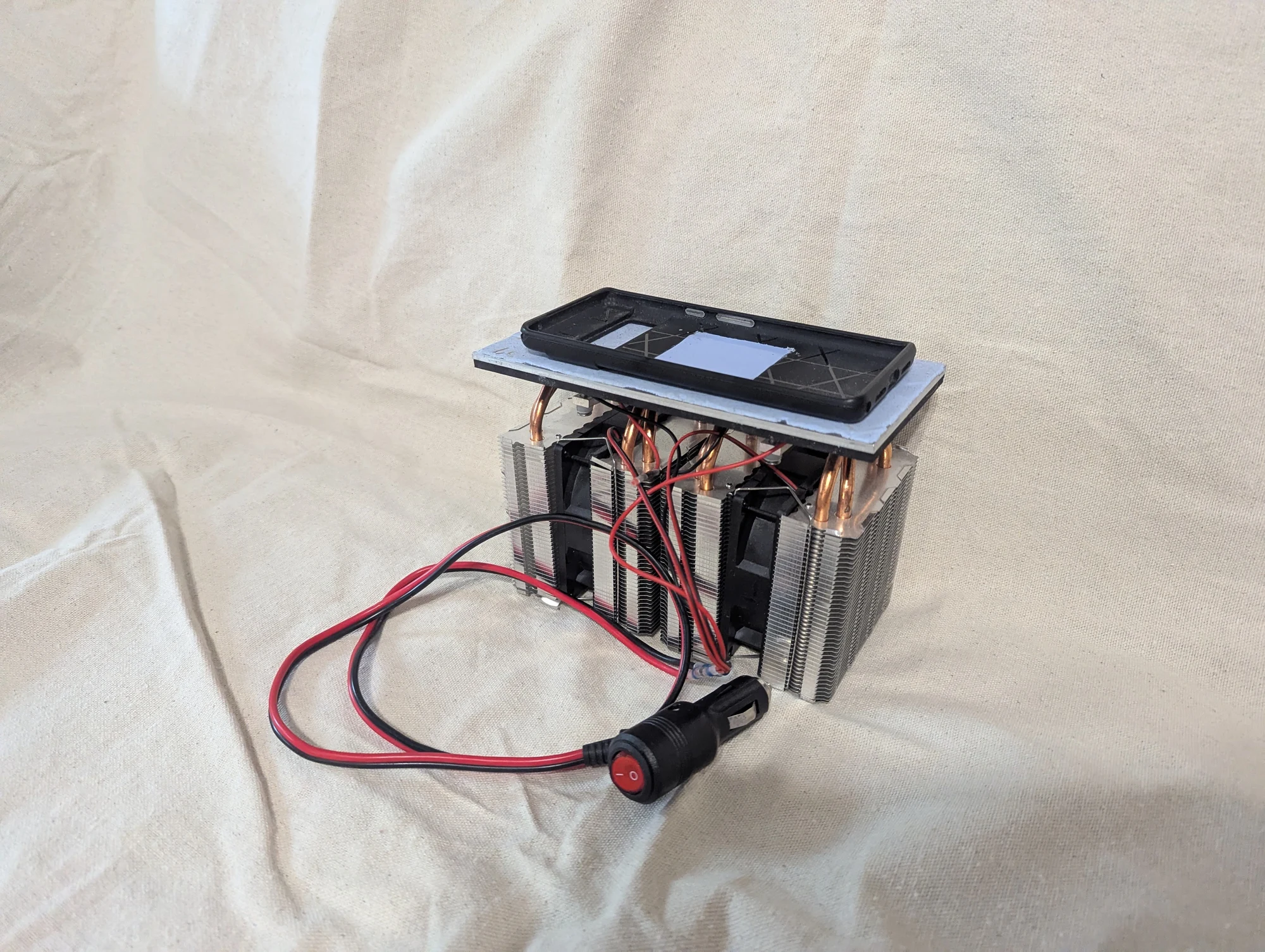
The phone case positioned over the thermoelectric cooler. The silicone thermal pad was intended to create a heat-transfer path between the back of the phone and the cooling surface.
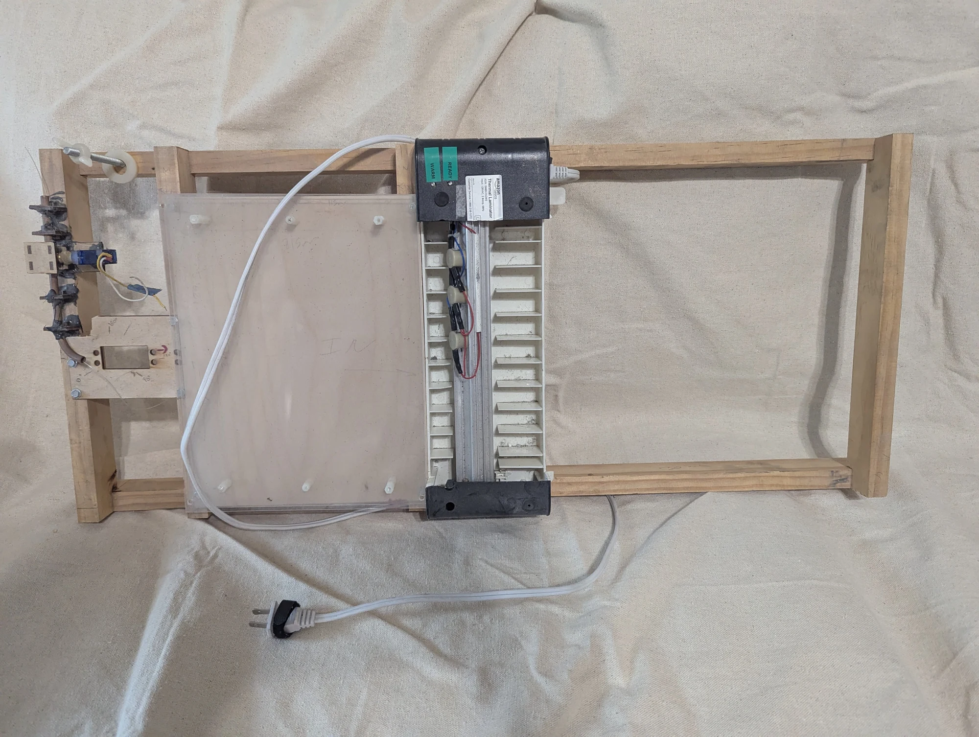
An experiment in making long, narrow channels for water or air inside laminated plastic. I tried feeding fishing line between the sheets as they passed through a laminator to form the channels. I also found that Sharpie ink could keep selected areas from bonding.
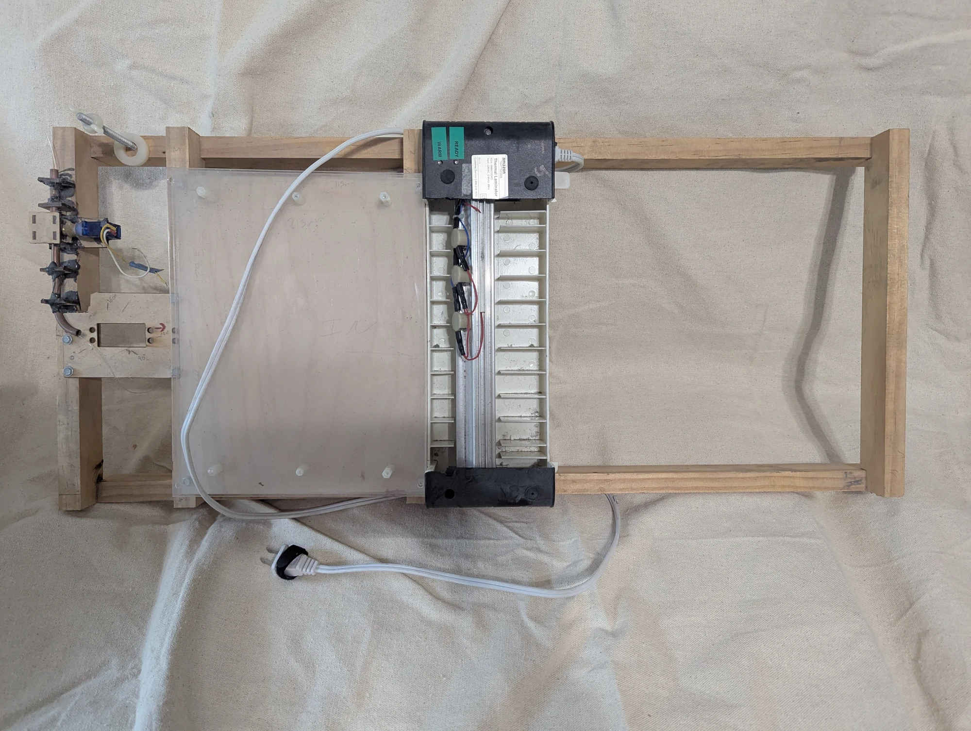
Another view of the laminator setup. Drawing Sharpie patterns on the plastic kept those areas from sticking together, offering an alternative way to form small passages for water or air.
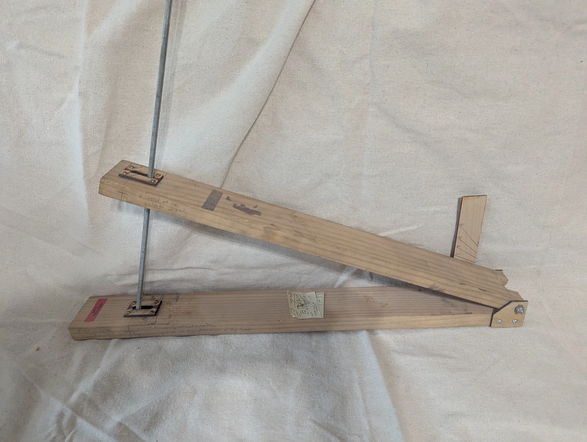
A tilting platform for studying how easily droplets slide off different surfaces, including water-repellent coatings. The intended measurement was the angle at which a drop began to move. This supported experiments with tiny fluid-control valves, including using oil droplets to cover or uncover openings.
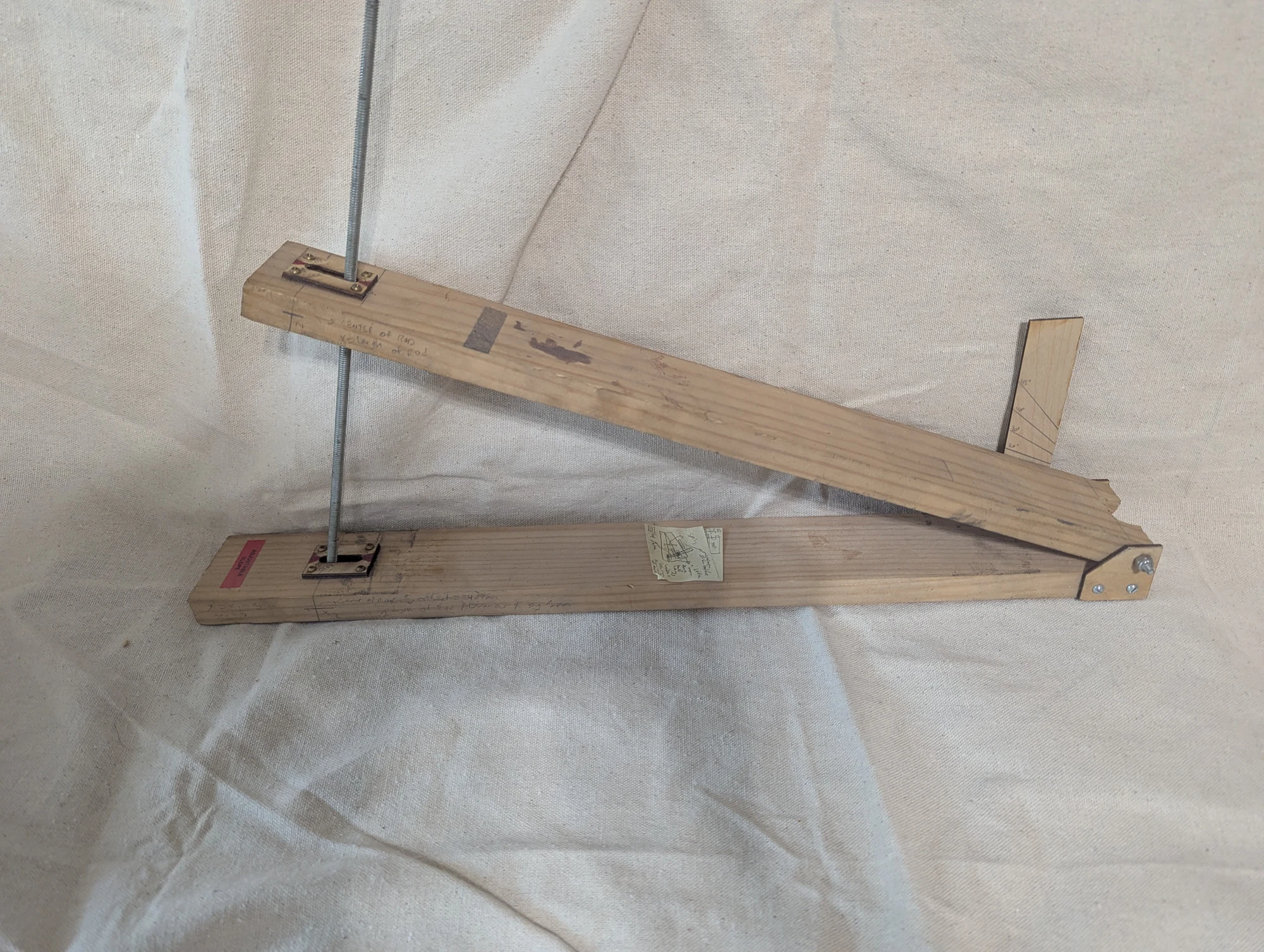
Another photograph of the tilting device shown in Photo 260. I used it to measure the angle at which a droplet began to roll or slide off a surface, helping me compare how strongly different surfaces held onto the liquid.
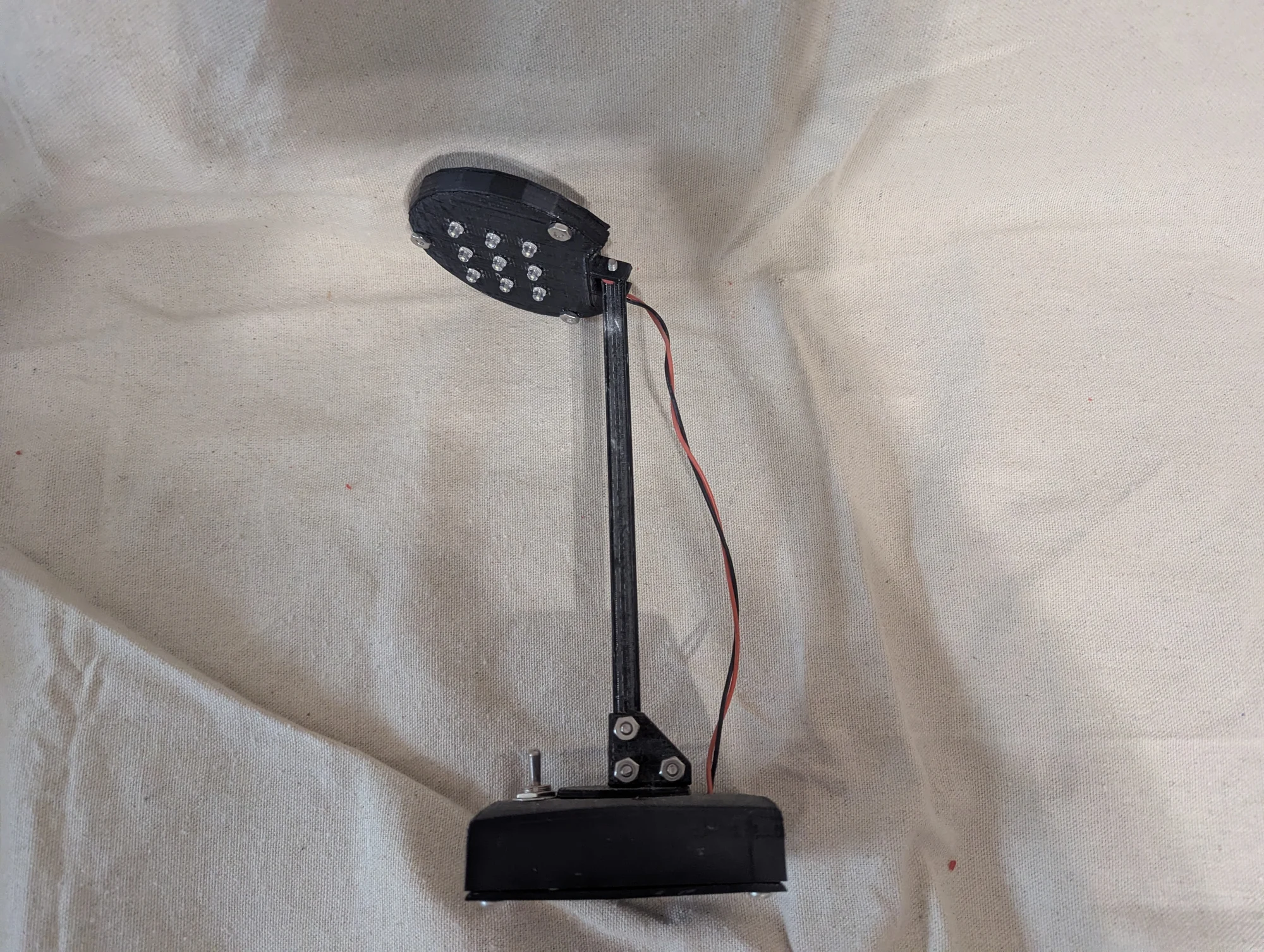
My LED lamp submission for a Lockheed Martin competition to make a 3D-printed object. It was a project I enjoyed, although it did not win.
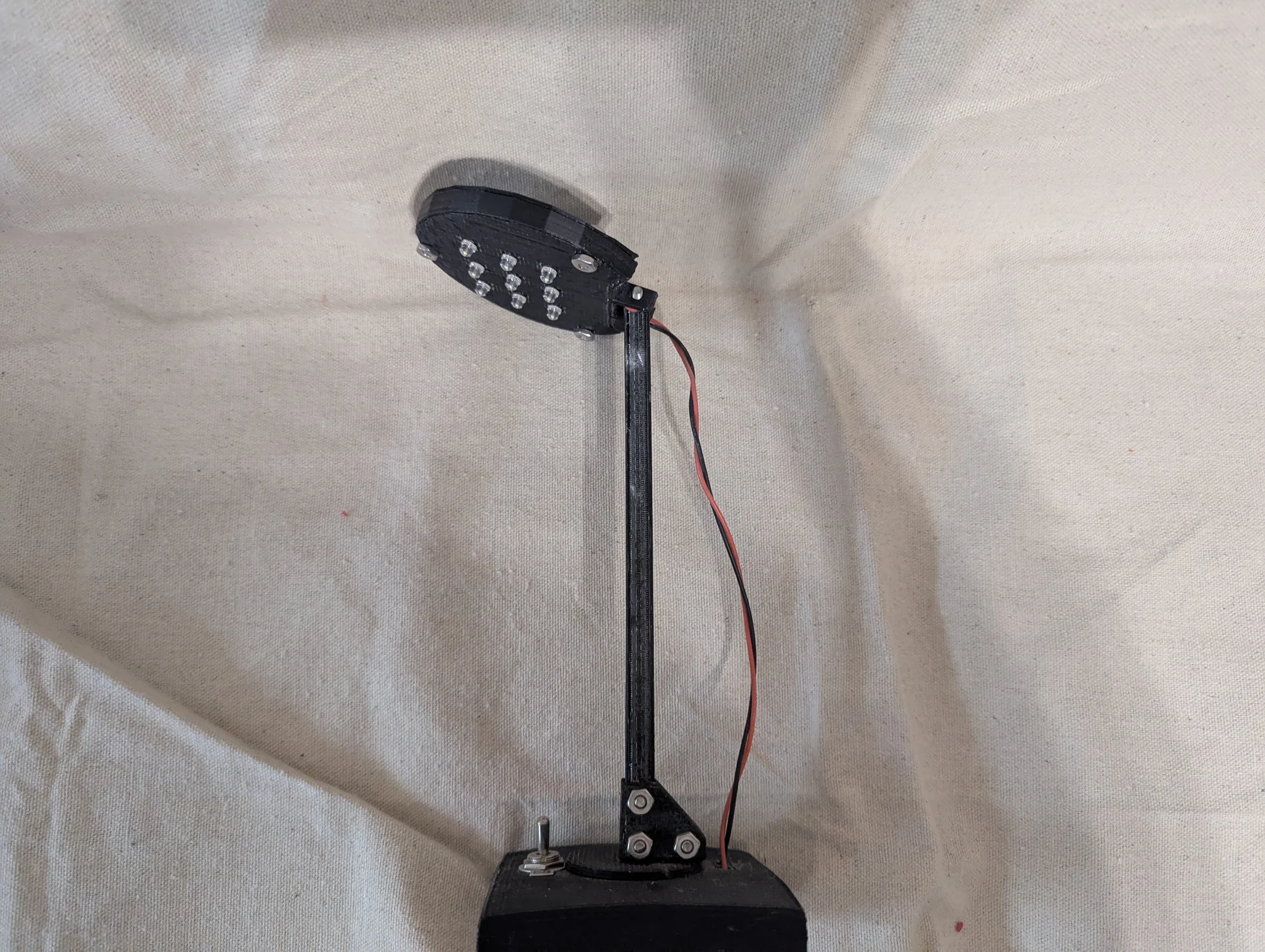
Another view of the 3D-printed LED lamp I entered in the Lockheed Martin design competition.
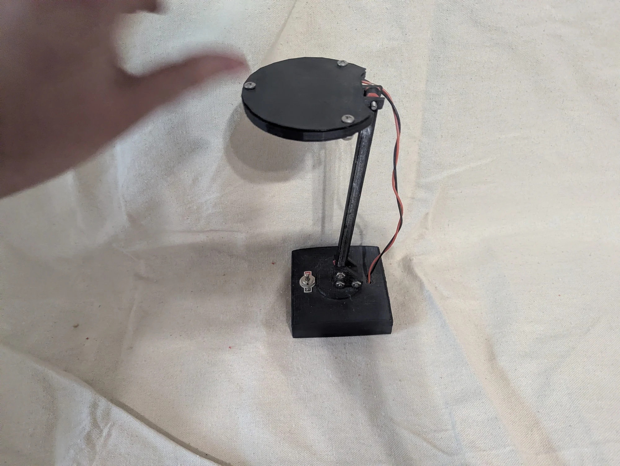
A different angle on the same LED lamp, showing more of the form I designed for the 3D-printing competition.
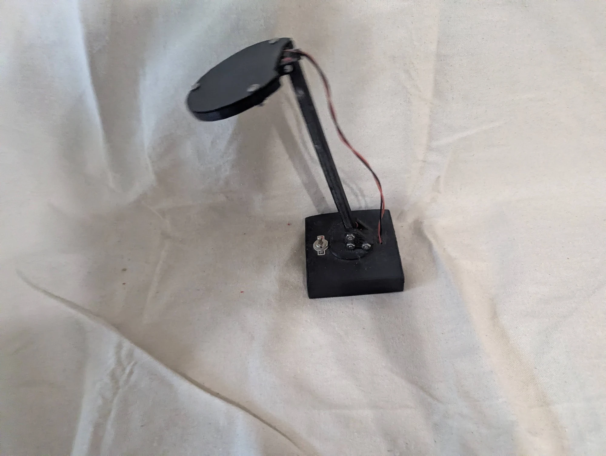
An additional view of my Lockheed Martin competition entry: a lamp combining a 3D-printed structure with LED lighting.
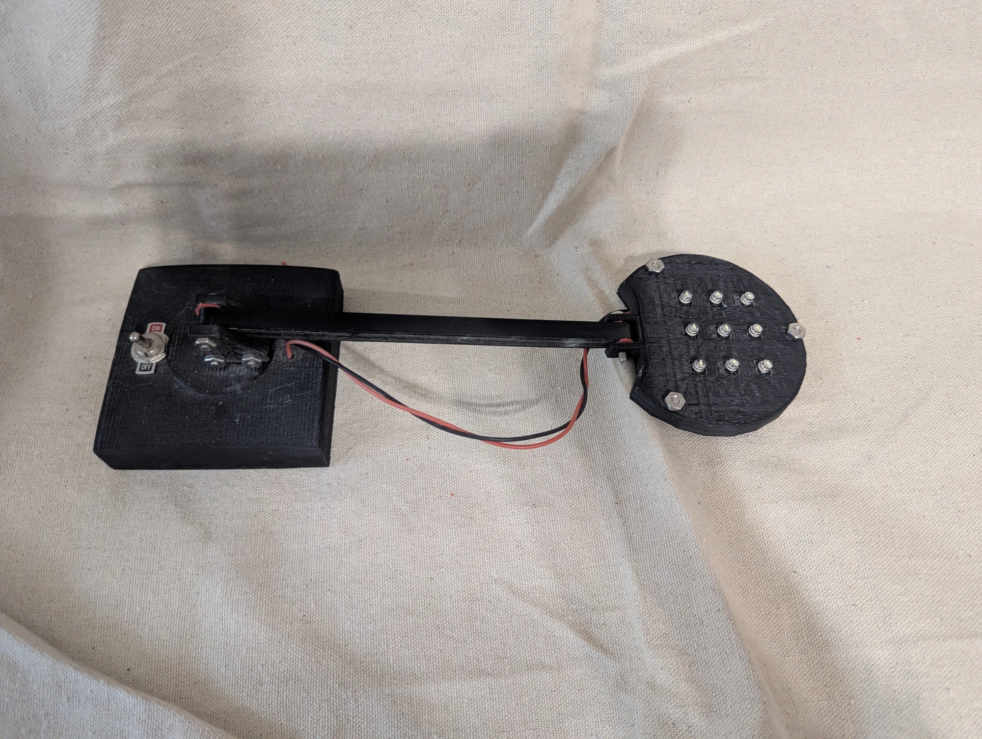
Another angle on the completed LED lamp prototype from the 3D-printing competition.
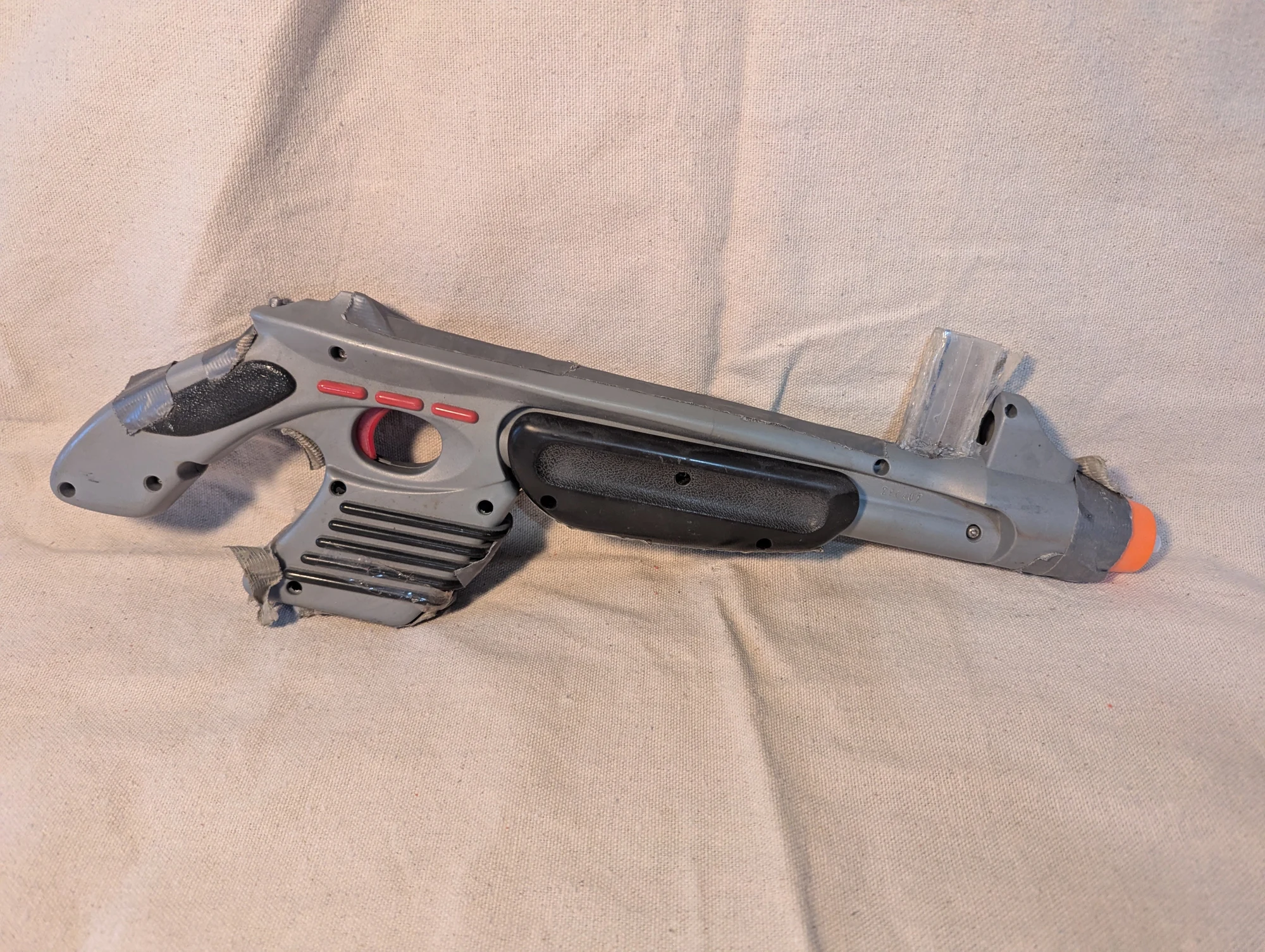
An early coilgun modification I made during middle or high school, incorporating a camera-flash charging circuit. This is the school-years prototype, which predates the later magnetic-launcher designs shown in this project. I do not recall the exact year.
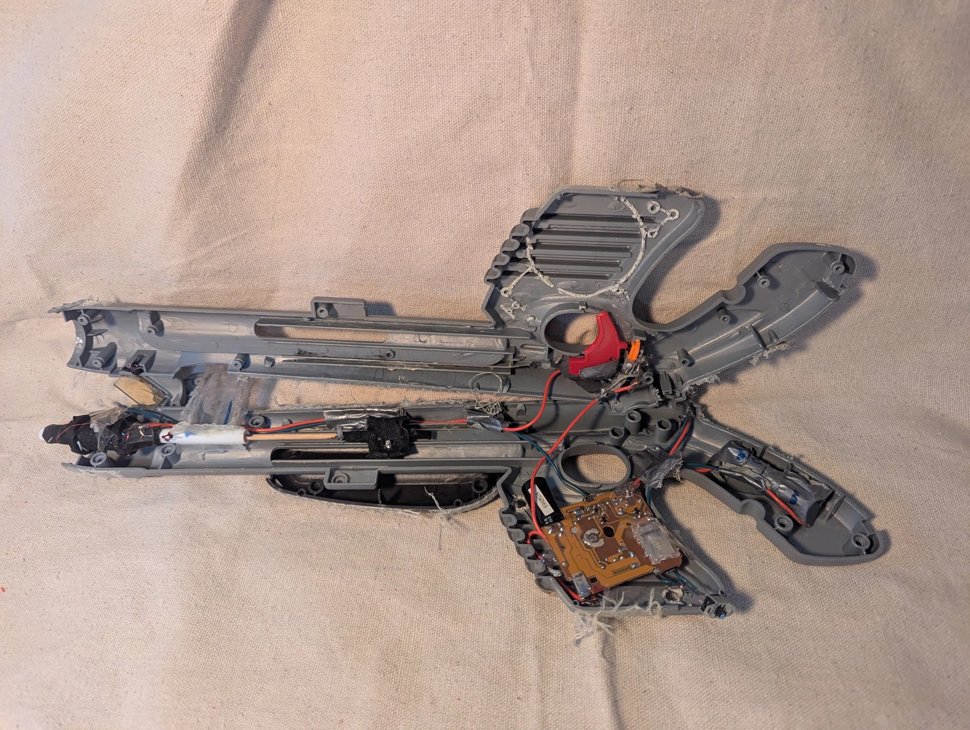
An interior view of the coilgun modification I made during middle or high school, showing its circuit hardware and wiring. This belongs to the early school-years prototype rather than the later versions.
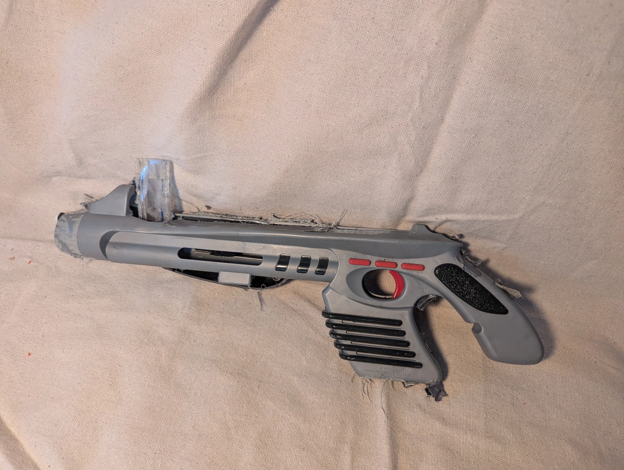
Another exterior view of the coilgun modification I made during middle or high school. This is the same early prototype shown in Photos 267–272; the later designs are shown separately in this project.
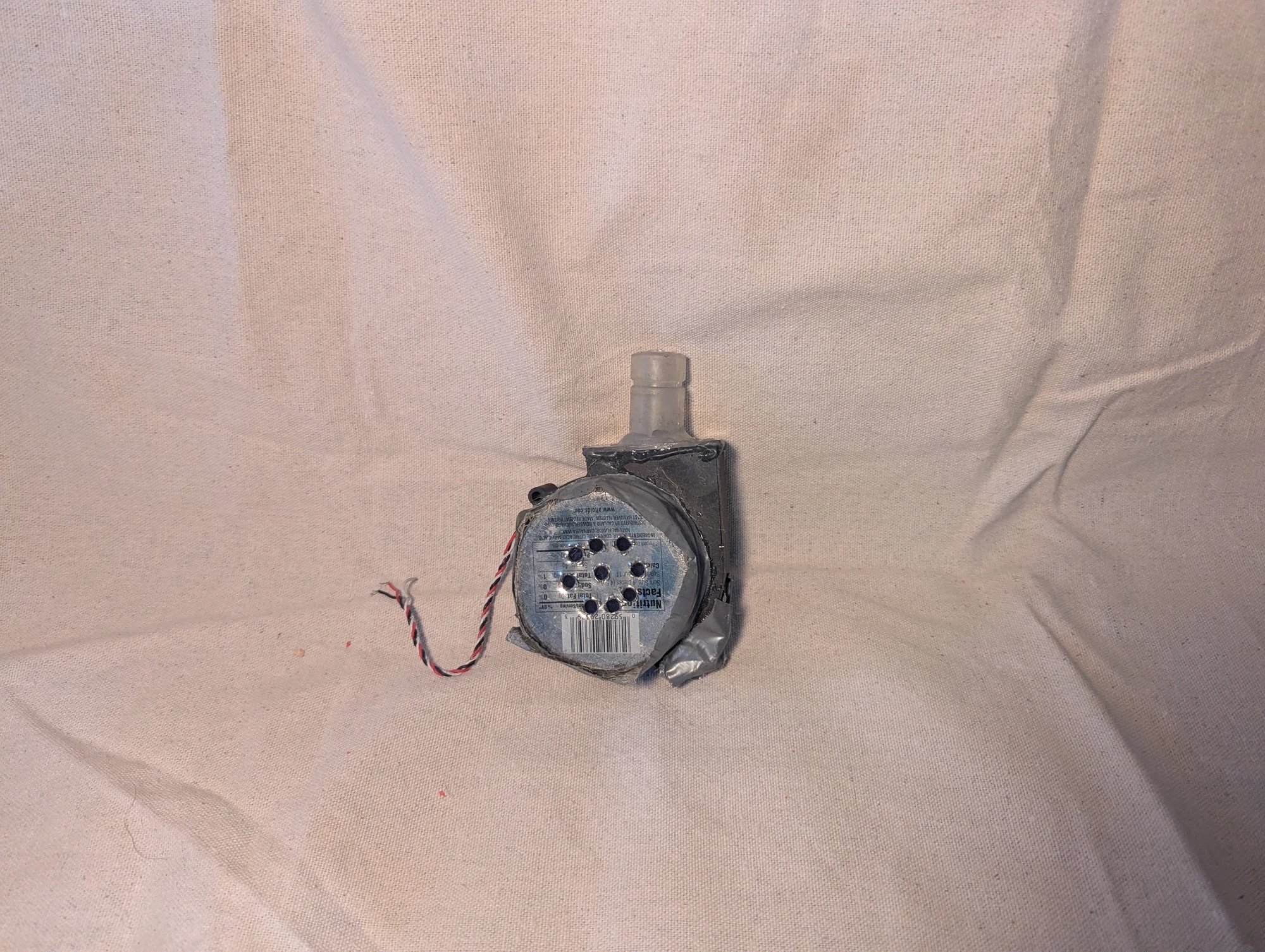
A fan-powered filter I made, probably during middle or high school. I do not recall the exact year. Air enters through holes punched in a metal tin, passes through activated carbon inside, and is drawn through by the fan.
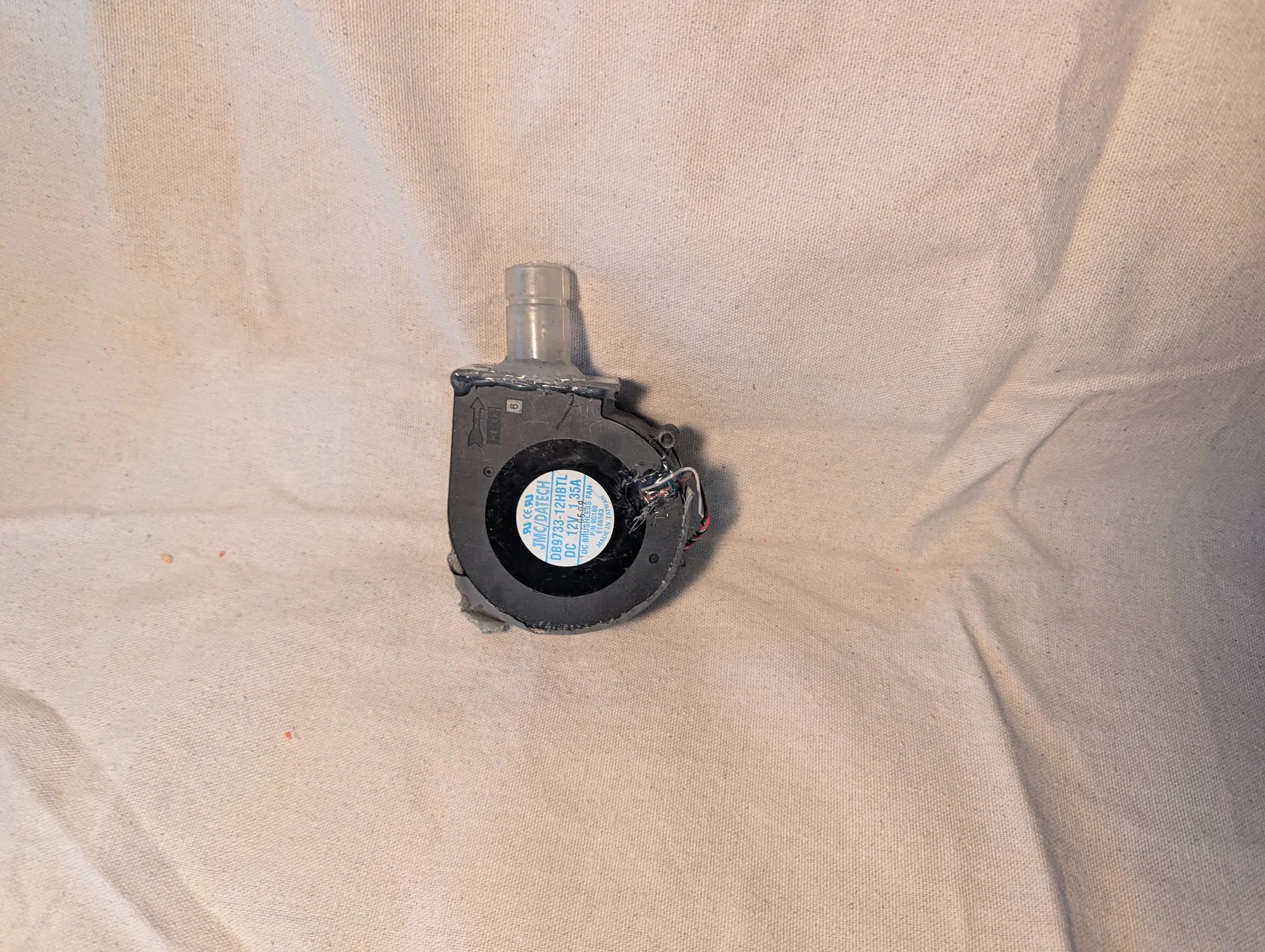
A second angle of the activated-carbon filter, showing the fan and metal-tin housing used to draw air through the carbon.
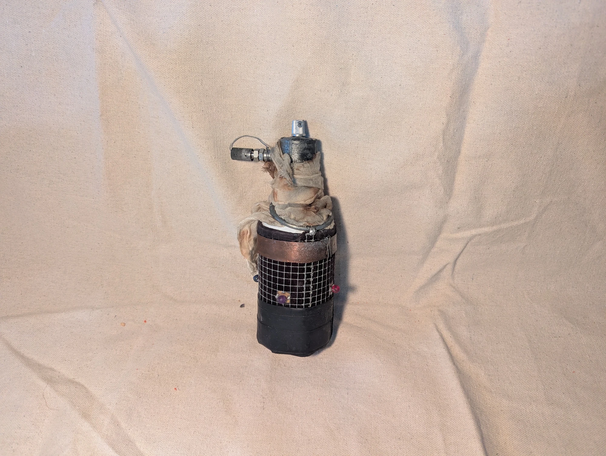
A chrome-spray applicator movie prop inspired by Mad Max: Fury Road. I combined felt, copper beads, brass plates, cheesecloth with oil, and rubber inner-tube material. Singeing was also part of creating its worn appearance.
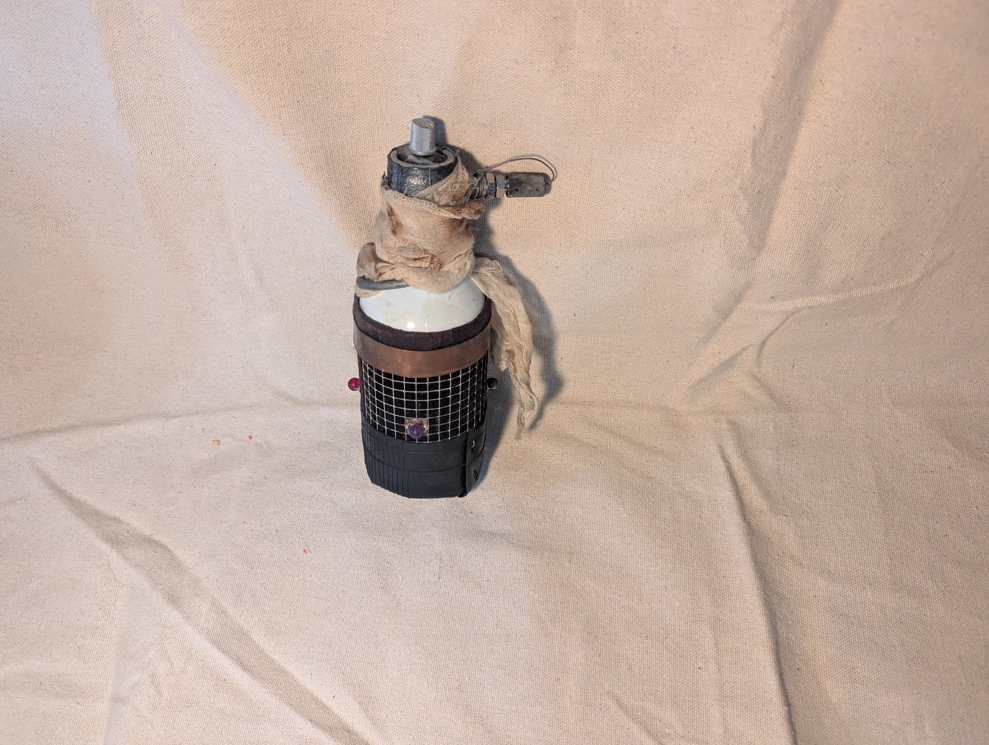
Another photograph of the chrome-spray applicator prop I made after watching Mad Max: Fury Road.
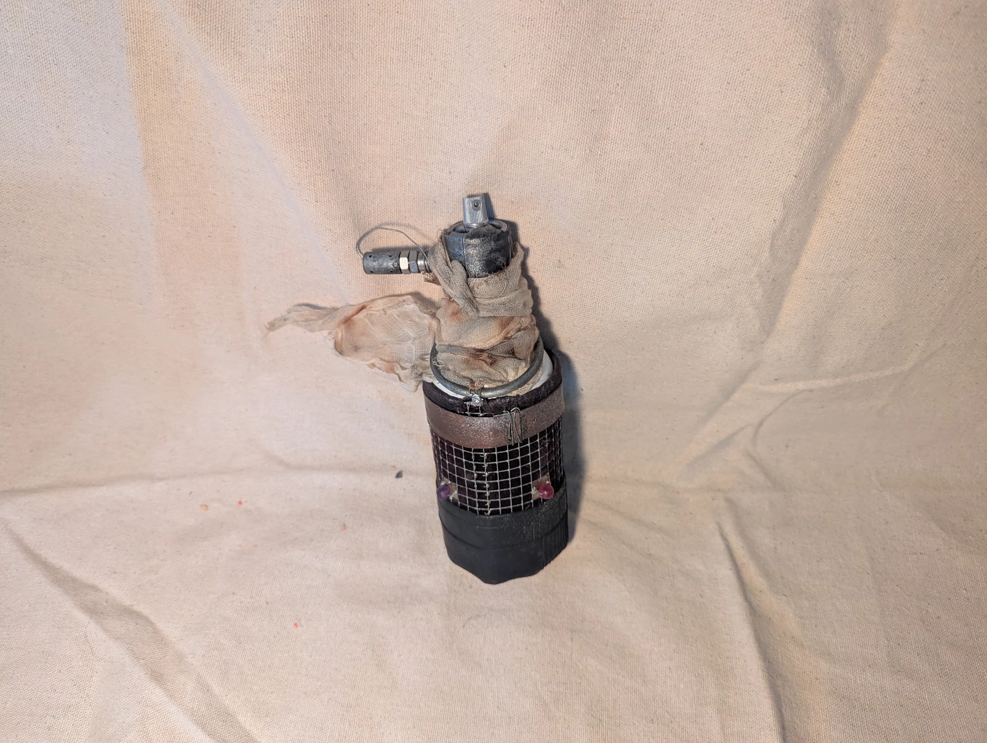
A different view of the same movie-prop project, with its combination of metal, fabric, and rubber materials.
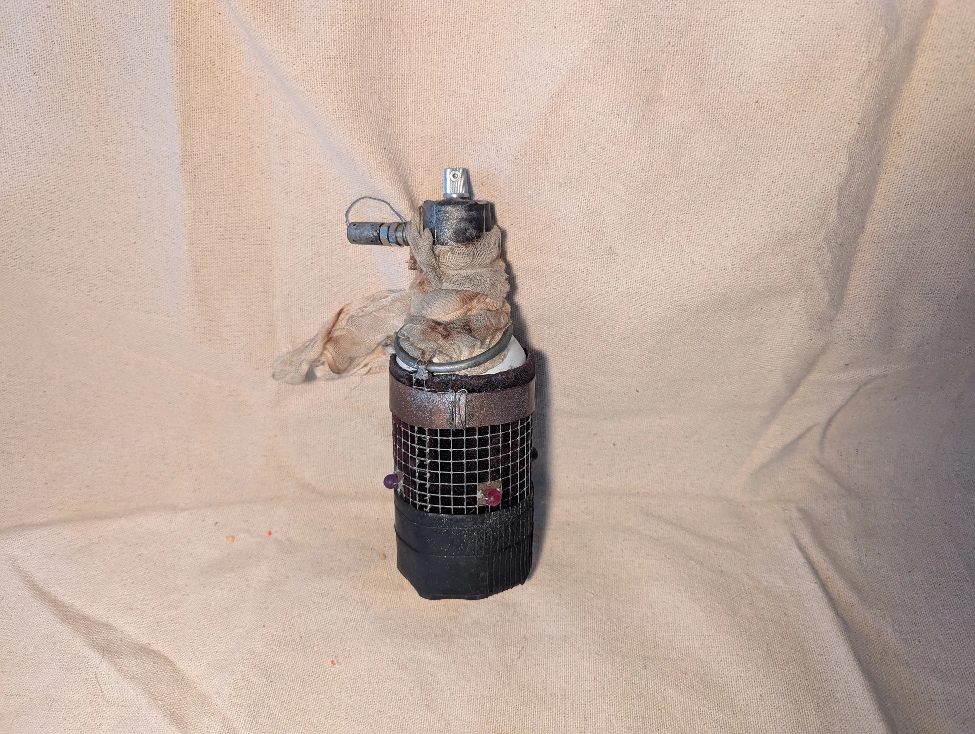
An additional view of my Mad Max-inspired chrome-spray applicator prop, documenting its assembled form and worn finish.
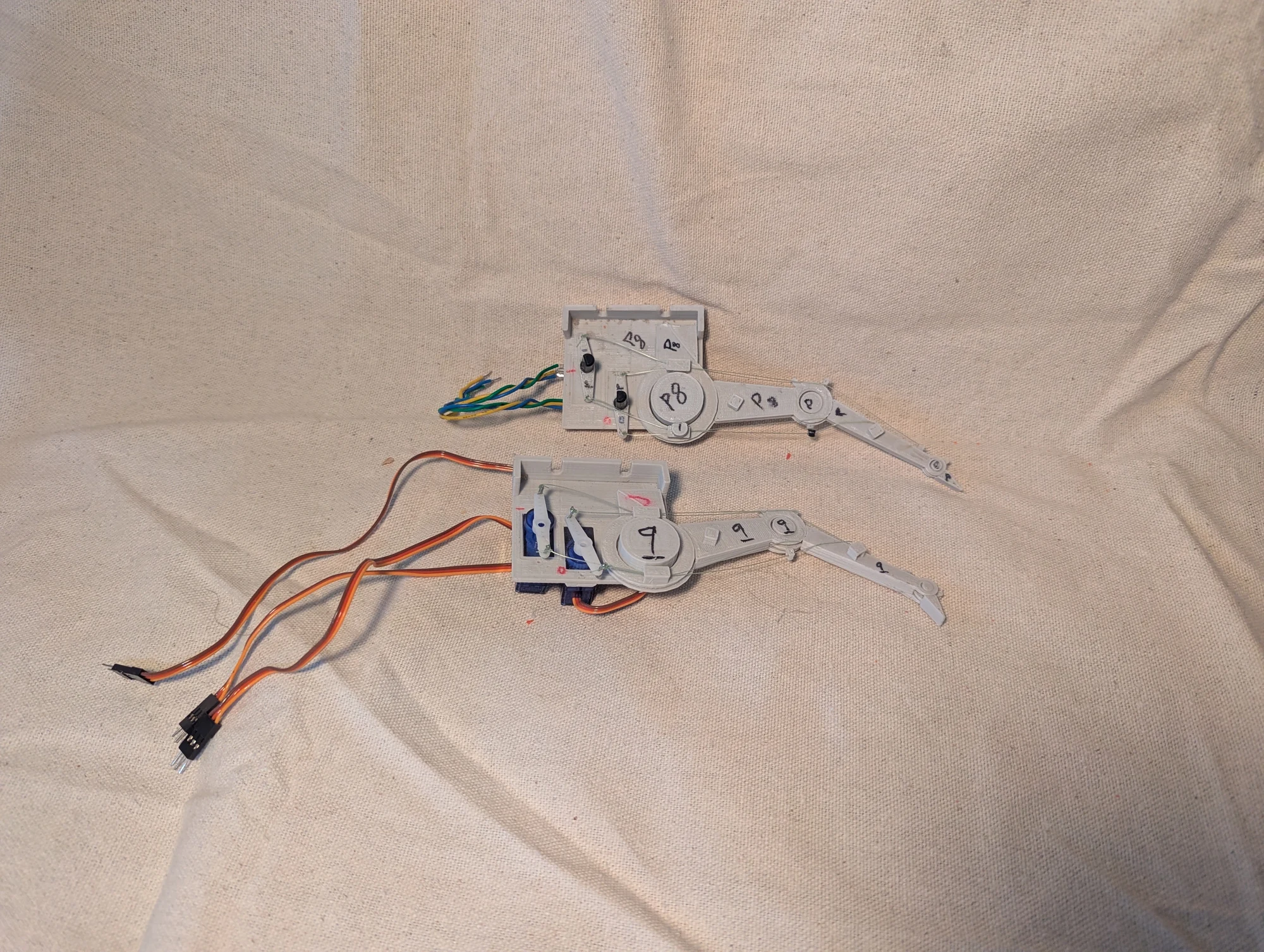
A crab-leg mechanism intended for an underwater crawling robot. Two servos pulled fishing lines attached to the joints. I moved a separate leg fitted with potentiometers, sensors that measure joint position, recorded those movements, and used them to guide the powered leg. It produced a crawling motion, but the mechanism was too delicate for an autonomous robot.
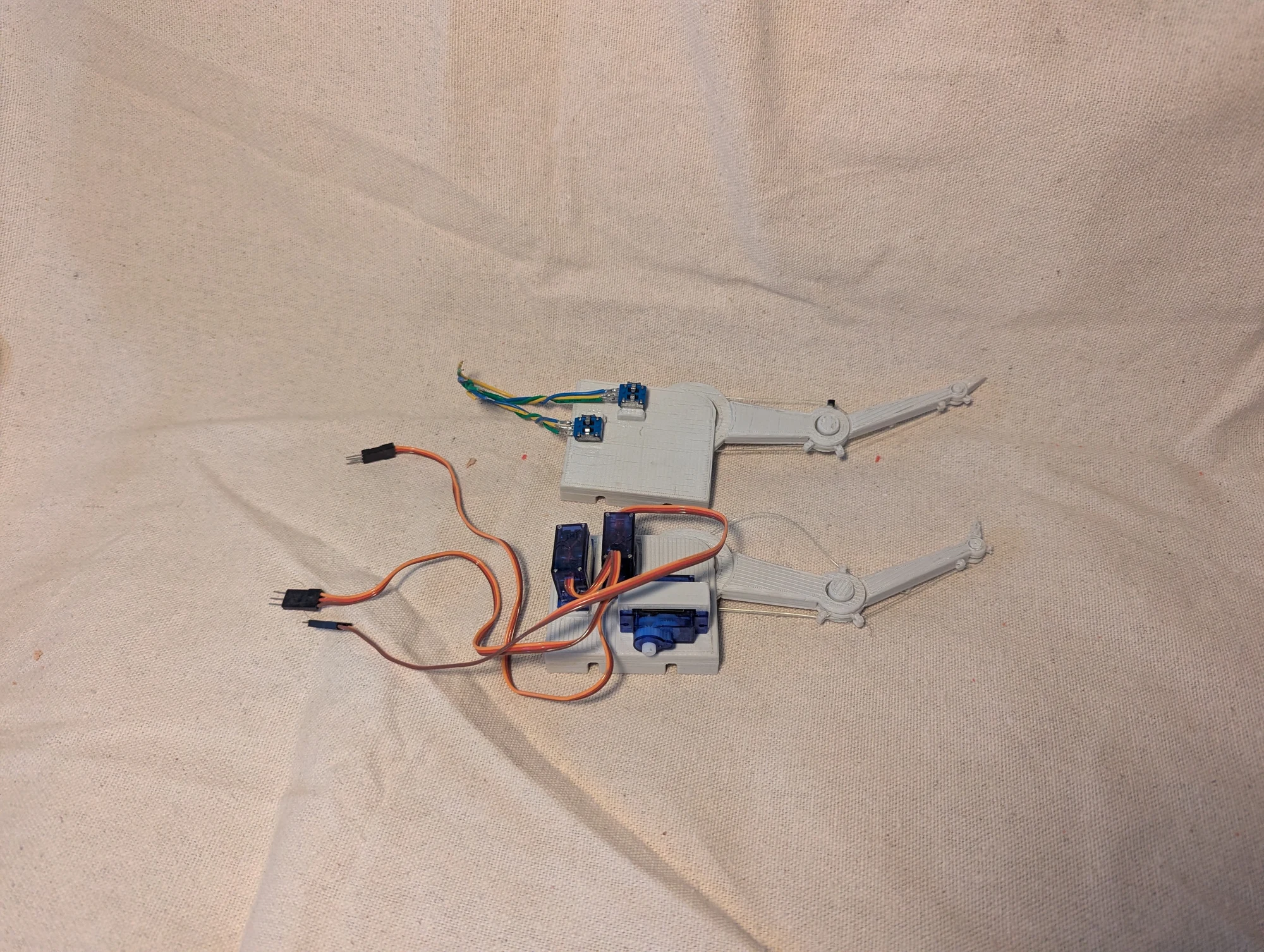
A rear view of the crab-leg robot prototype, showing the mechanism from the opposite side.
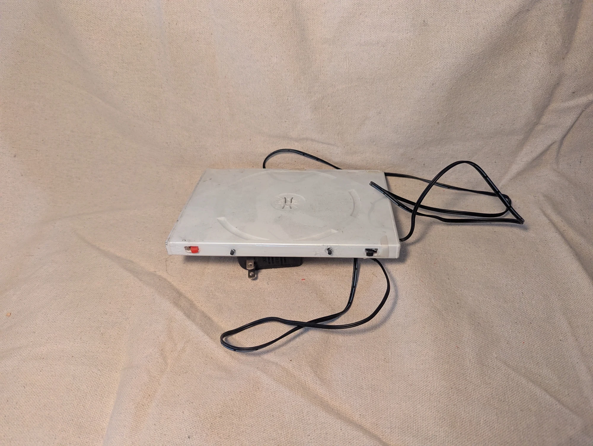
A Wii Remote housed in a DVD case tracks an infrared light. Its position is sent to a computer, which uses a projector to draw a line at the corresponding point, creating a smartboard-style drawing surface. I built the hardware with a partner at Hopkins School; my partner handled the software.
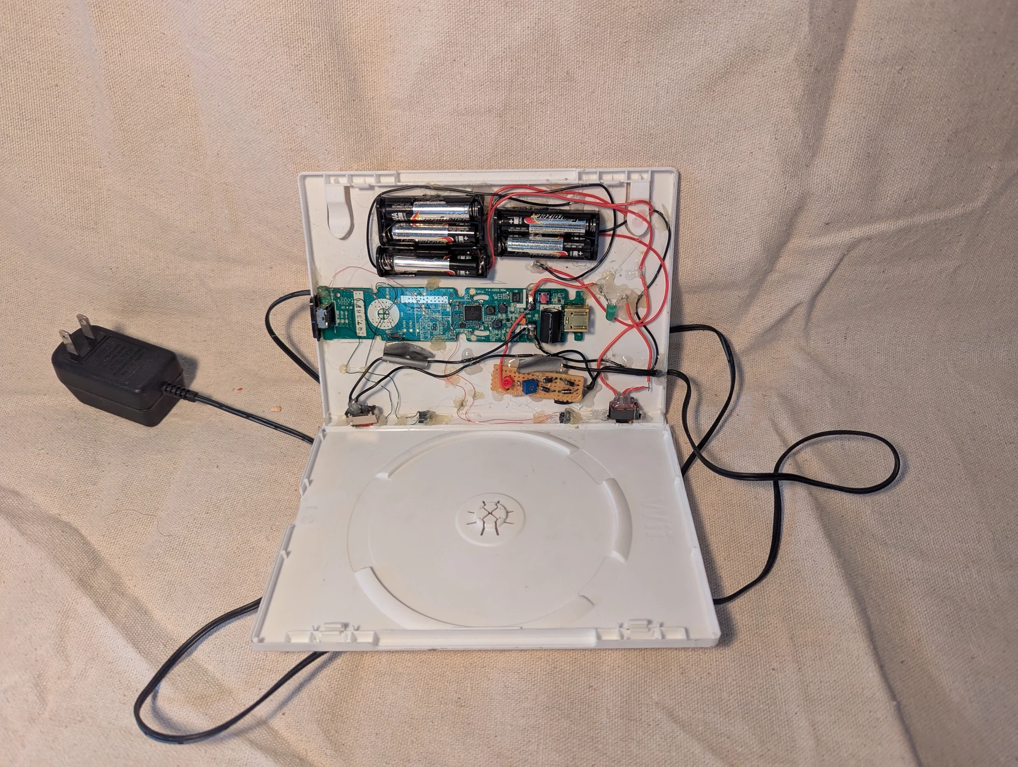
The Wii Remote and its power connections inside the DVD case. This was the hardware side of the smartboard project I developed with a partner at Hopkins School.
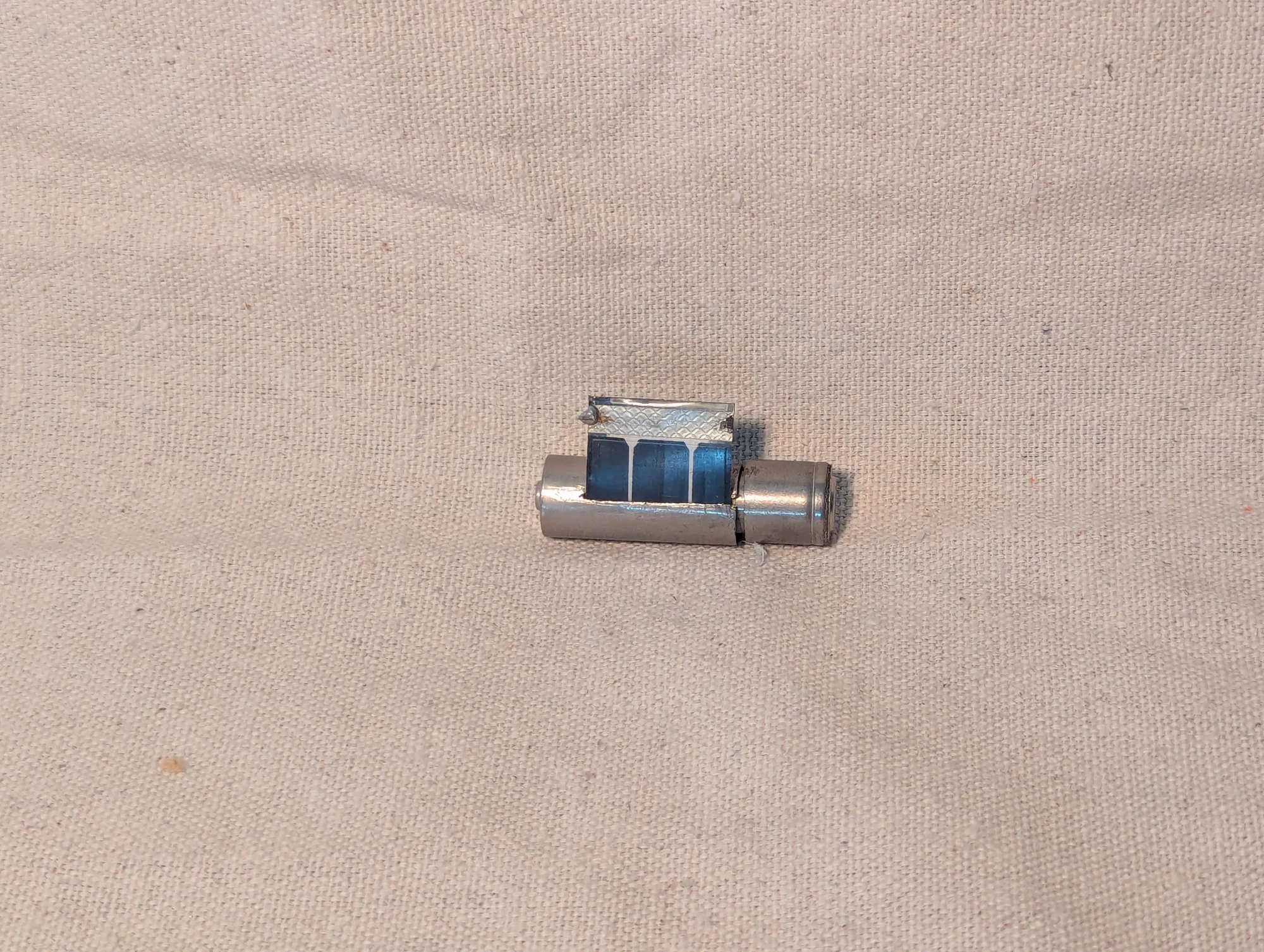
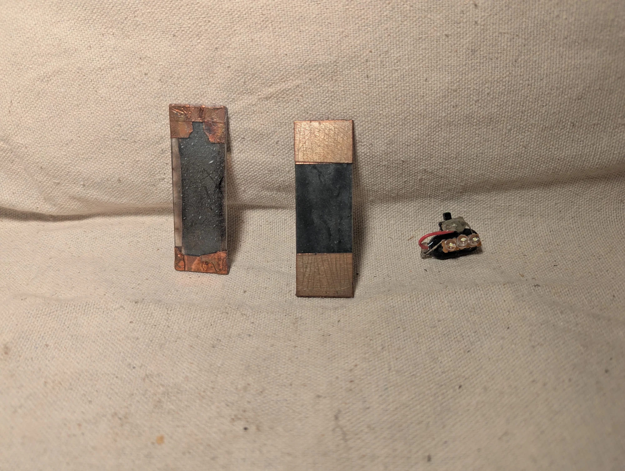
EKO Cell was a proof of concept I developed at Lehigh University: a AAA battery and flexible solar panel packaged inside an AA-sized shell. The idea was to have a rechargeable AA-size battery available when needed. The prototype did not include a charge-control circuit. It won third place and a $1,000 award in a university innovation competition, and taught me a great deal about pitching a product.
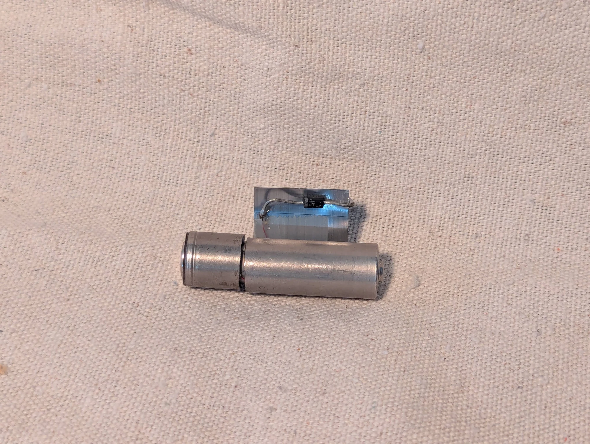
Another view of EKO Cell in its compact battery-shaped packaging. The concept combined a smaller AAA battery with a flexible solar panel inside an AA-sized shell.
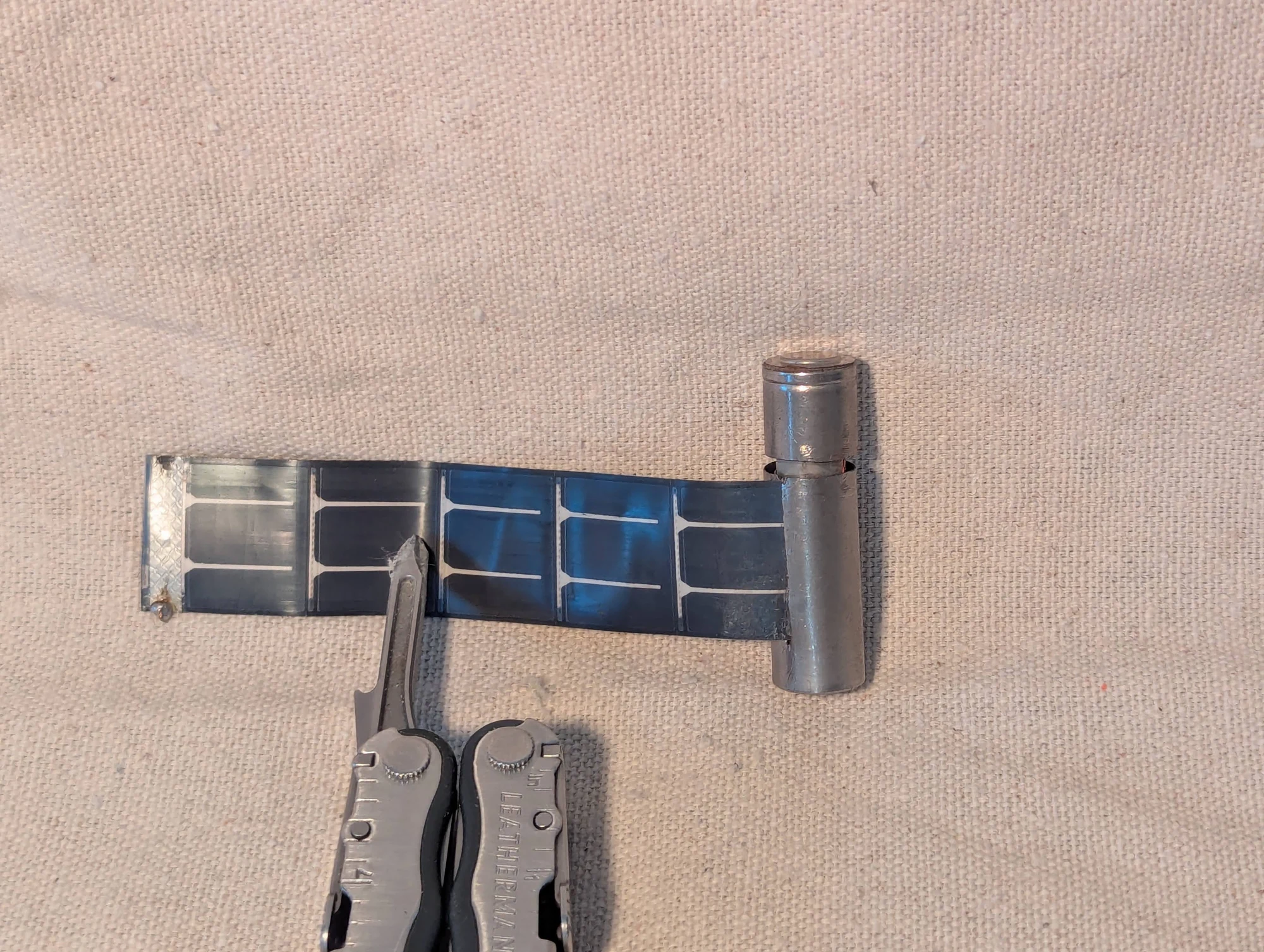
The flexible solar panel extended from the EKO Cell prototype. The project explored how solar charging could be packaged in the form of a familiar AA battery.
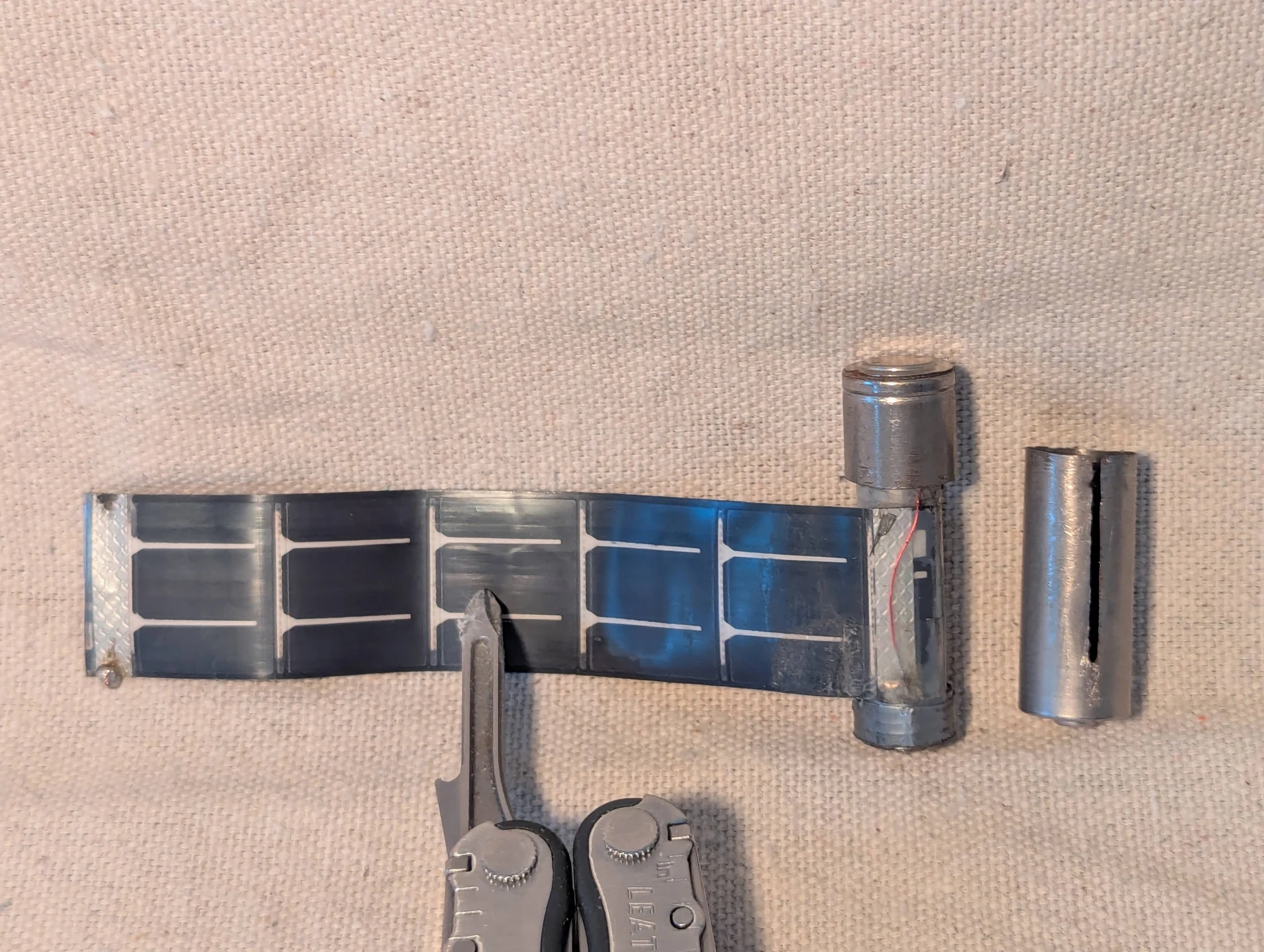
The EKO Cell prototype with its solar panel extended and its parts visible. This was a packaging and product concept; a charge-control circuit was not included in the prototype.
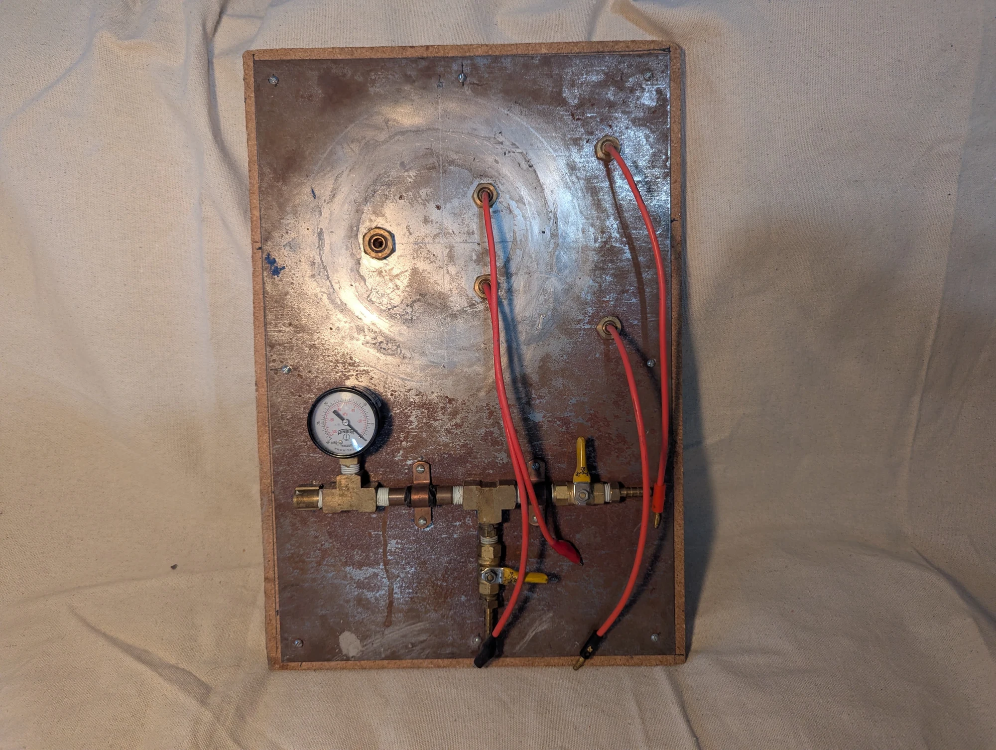
An early vacuum-chamber assembly with electrical feed-throughs and gas ports, built for plasma experiments. Threaded pipe fittings, silicone tubing, and wood parts made achieving a good vacuum difficult: some materials released gas under vacuum. I did produce a plasma. A large bell jar covered the assembly during use, but it is not shown here.
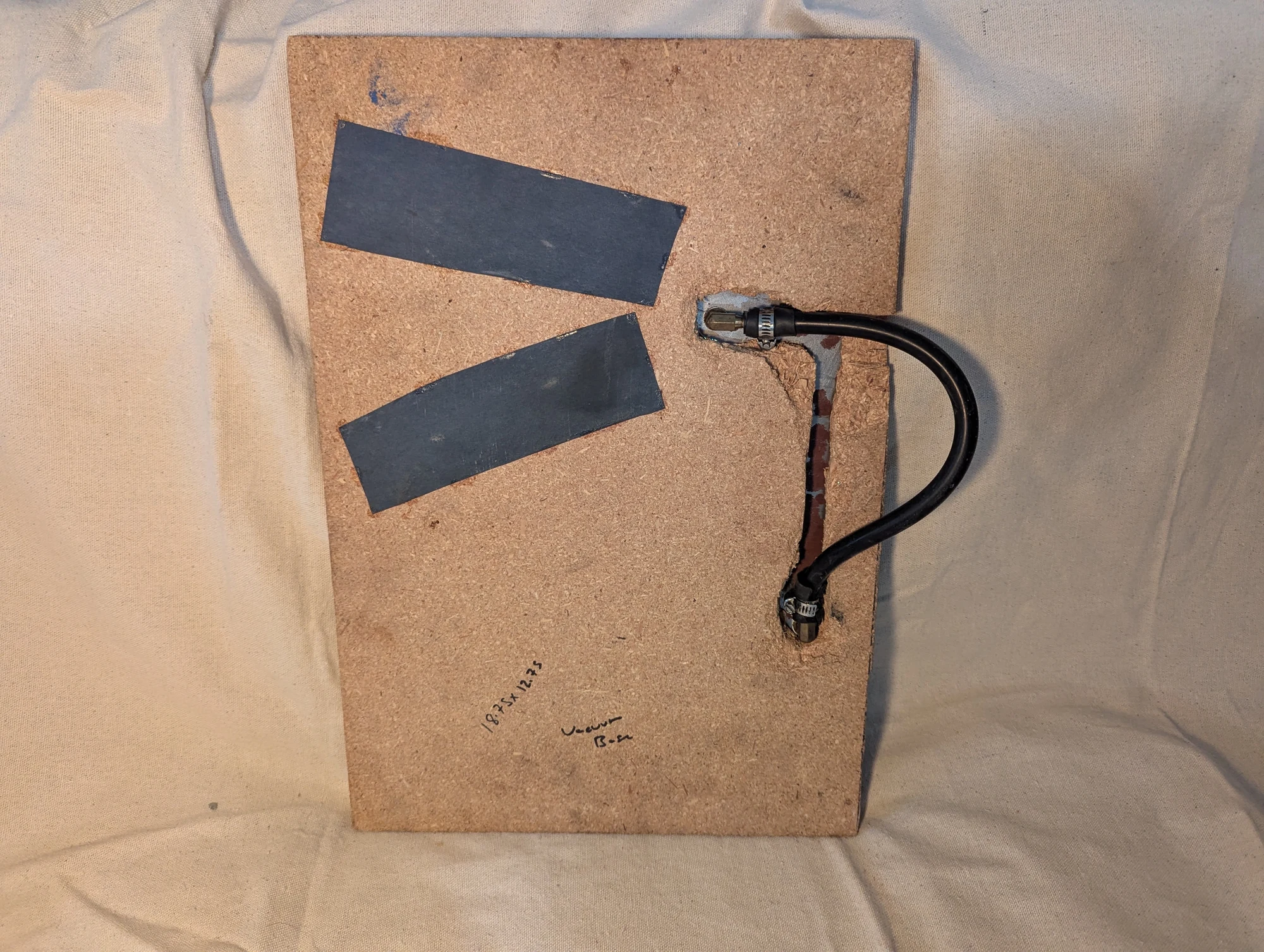
The rear of the early vacuum-chamber assembly, showing the supporting base and plumbing. This was part of the setup I used for plasma experiments beneath a large bell jar.
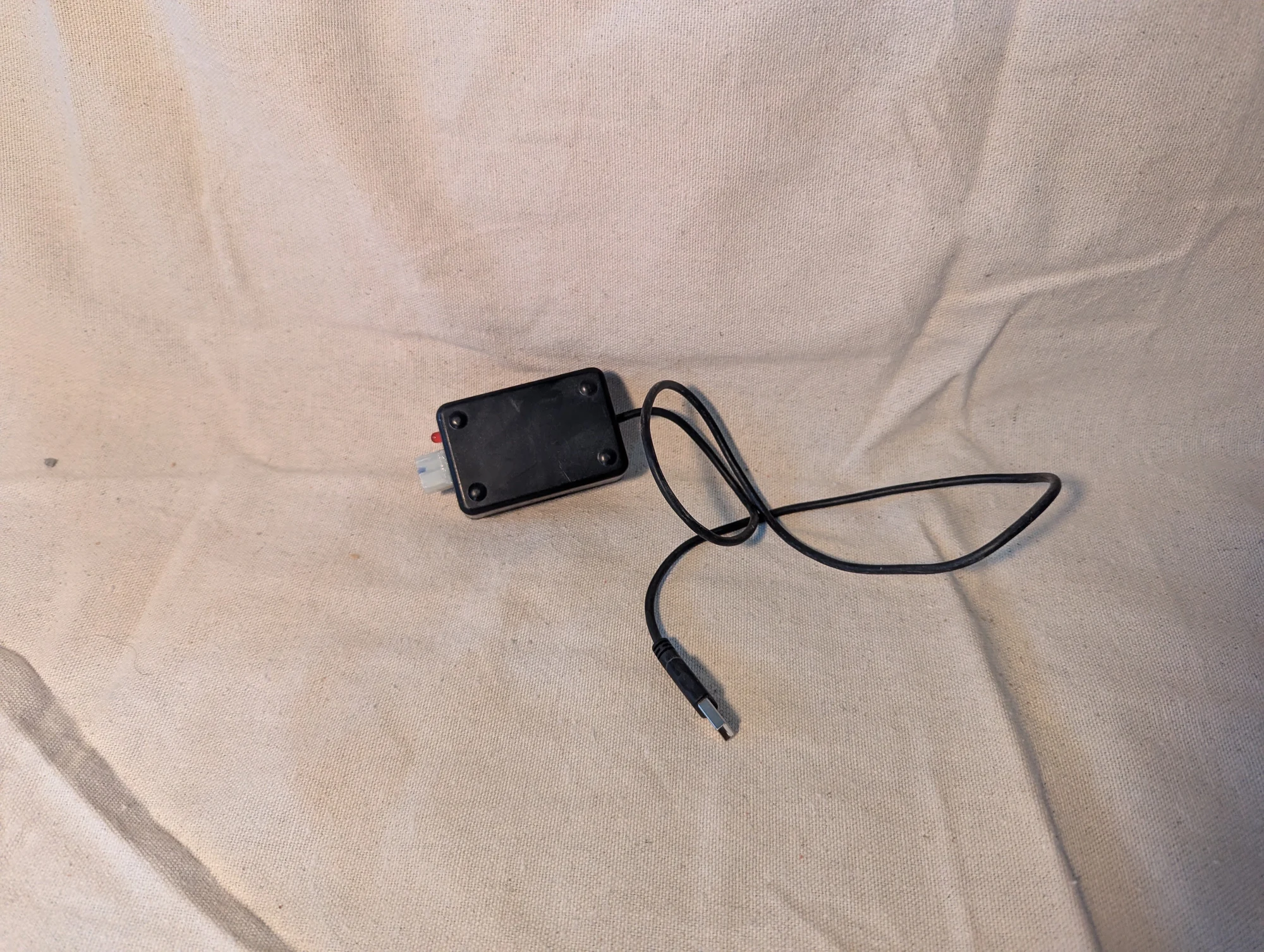
An early battery-charger project in its enclosure, with its attached cables.
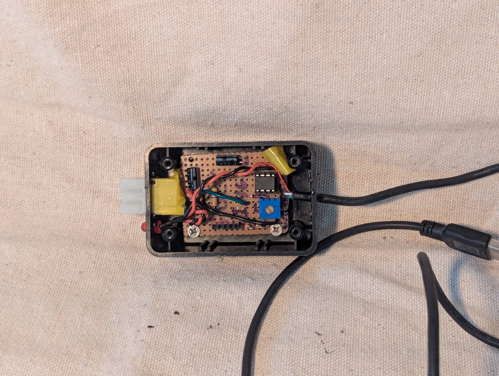
The battery-charger enclosure opened to show its circuit board and internal wiring.
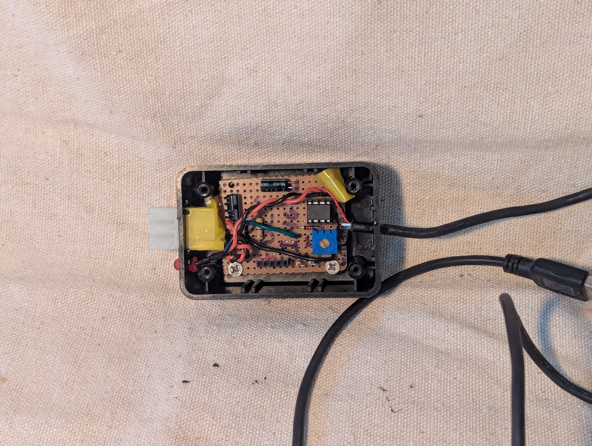
A second view inside the battery charger, showing the board and cable connections.
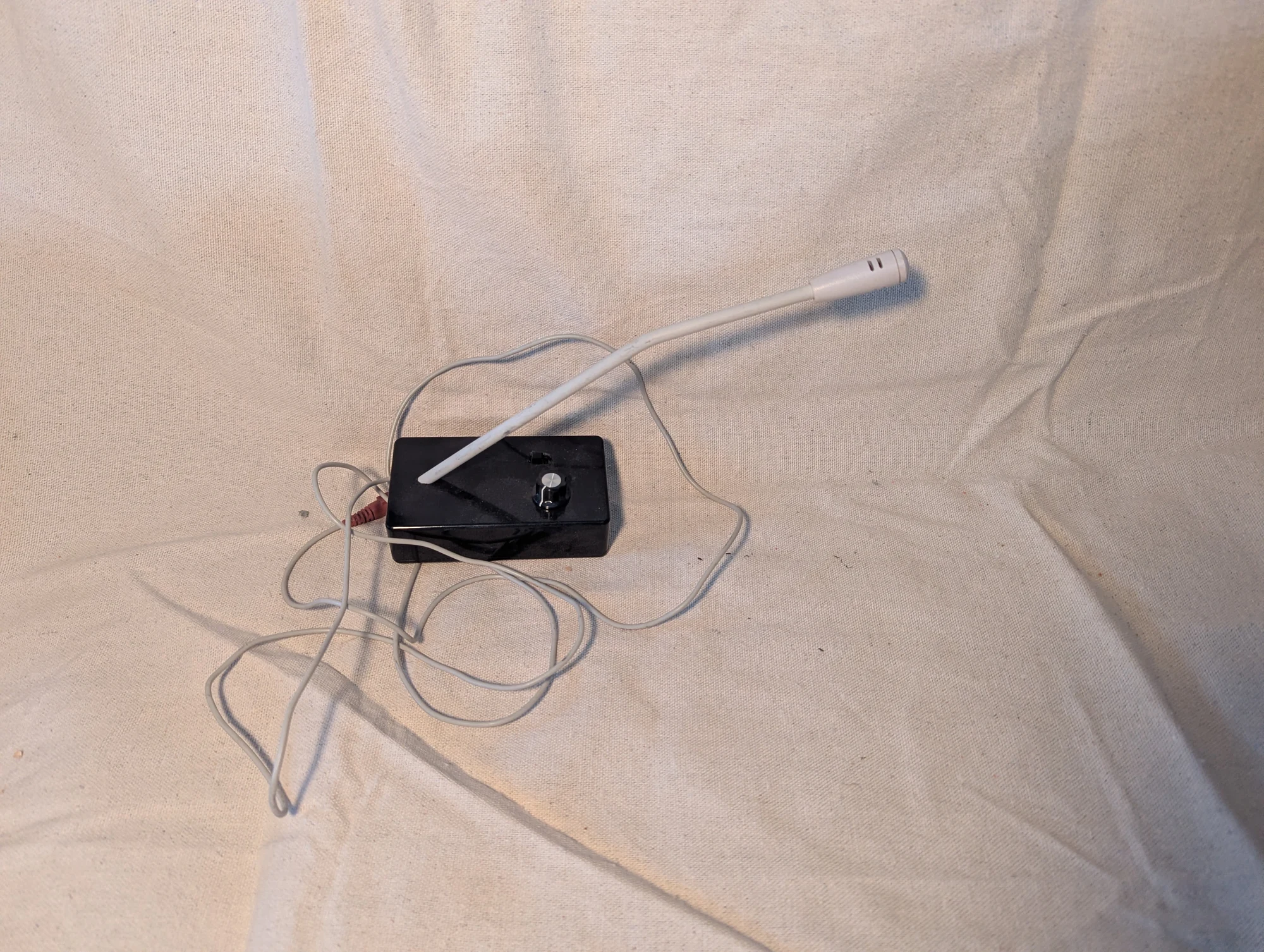
A computer microphone with adjustable gain, a control for how much the microphone signal is amplified. I do not believe I ever got this prototype working as intended.
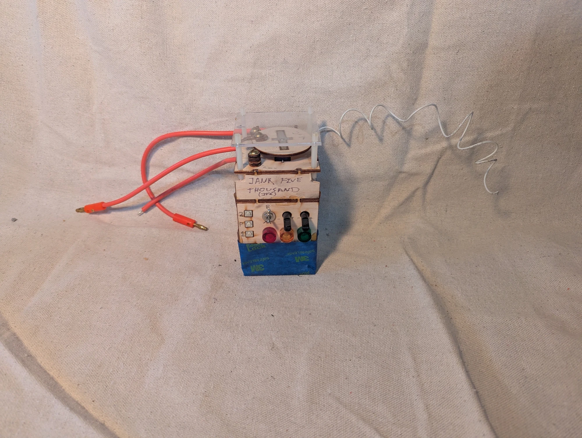
A remotely controlled switch I made for high-voltage capacitor experiments so I could operate it from a distance. It used a basic remote-control module. It worked, but I considered it a rough experimental build, reflected in the nickname “jank” on the enclosure.
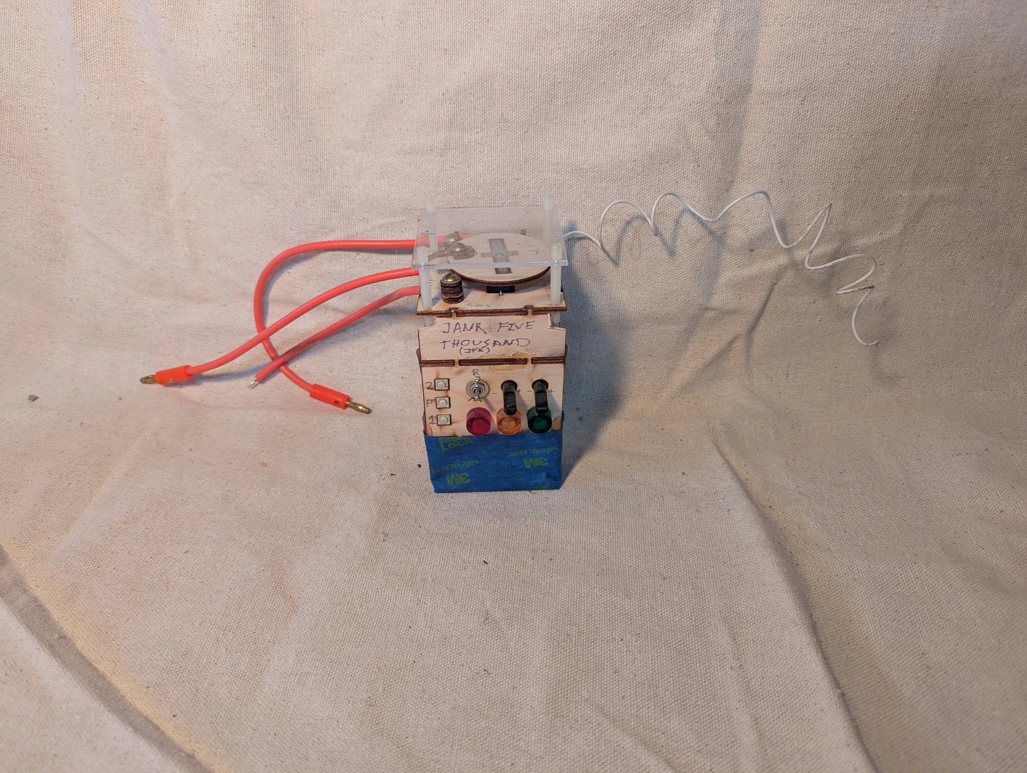
A second view of the remote-controlled switch used in my early capacitor experiments. Remote operation let me trigger it without standing beside the experimental setup.
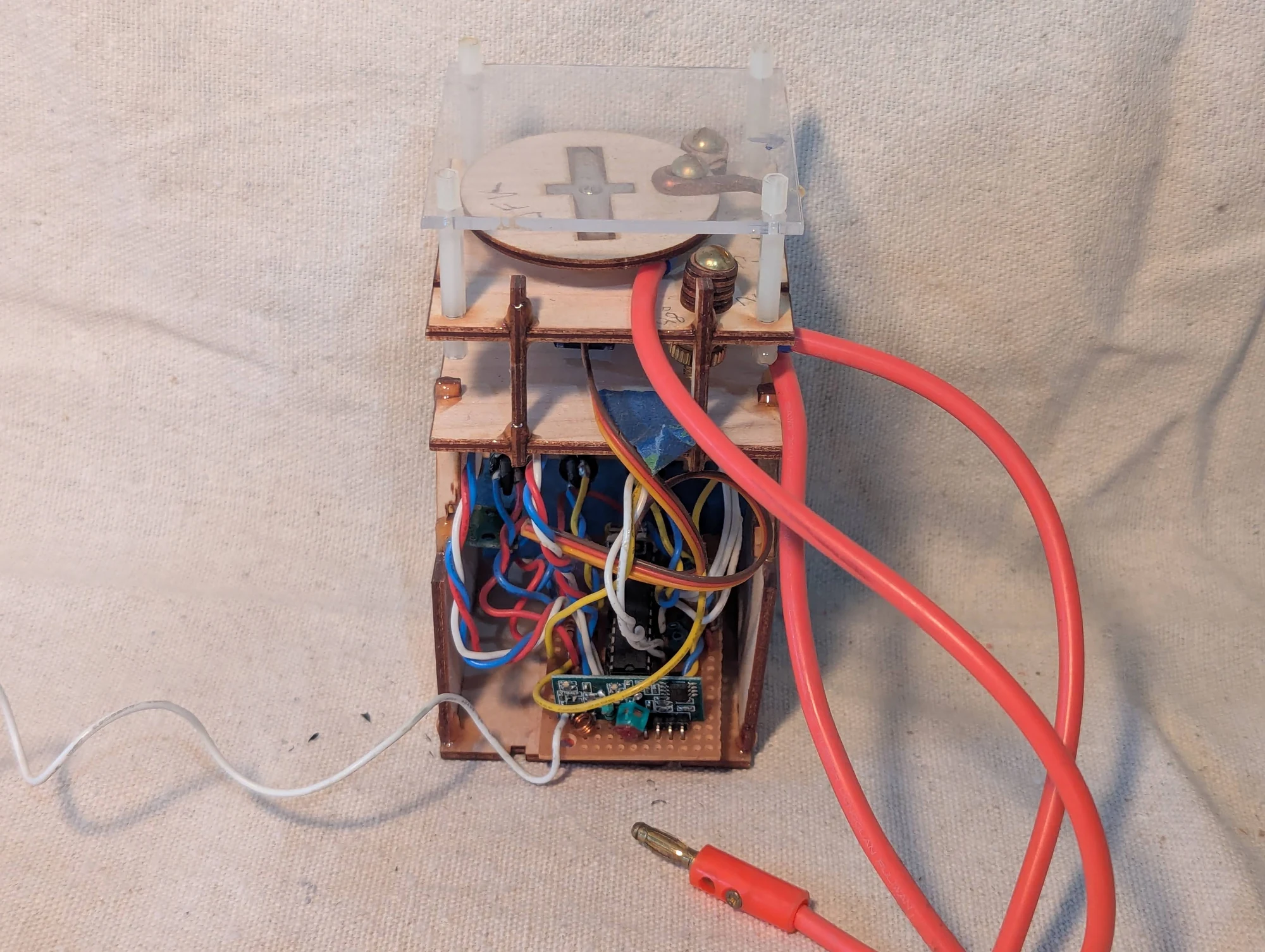
The remote-switch enclosure opened to show the control module and wiring. This was an early experimental build for operating capacitor tests from a distance.
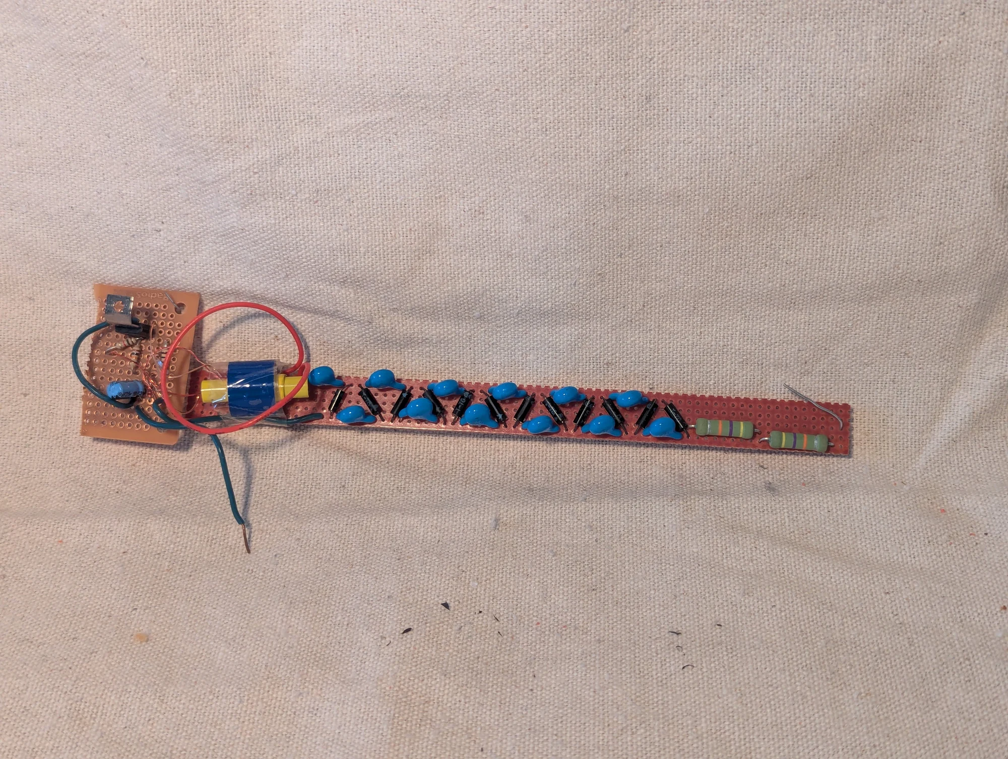
An early voltage-multiplier project, a circuit that raises voltage in stages. It may have come from a kit, but I no longer recall the exact kit or date.
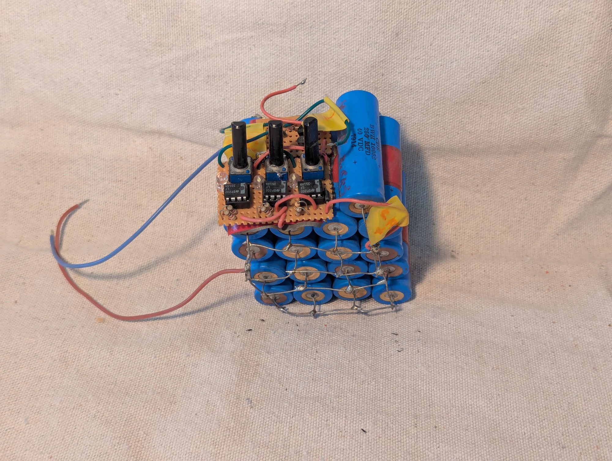
A capacitor bank I assembled from spare capacitors, possibly during college. A capacitor bank stores electrical energy in a group of components. The charging electronics on top used comparator circuits and LEDs to indicate different voltage levels.
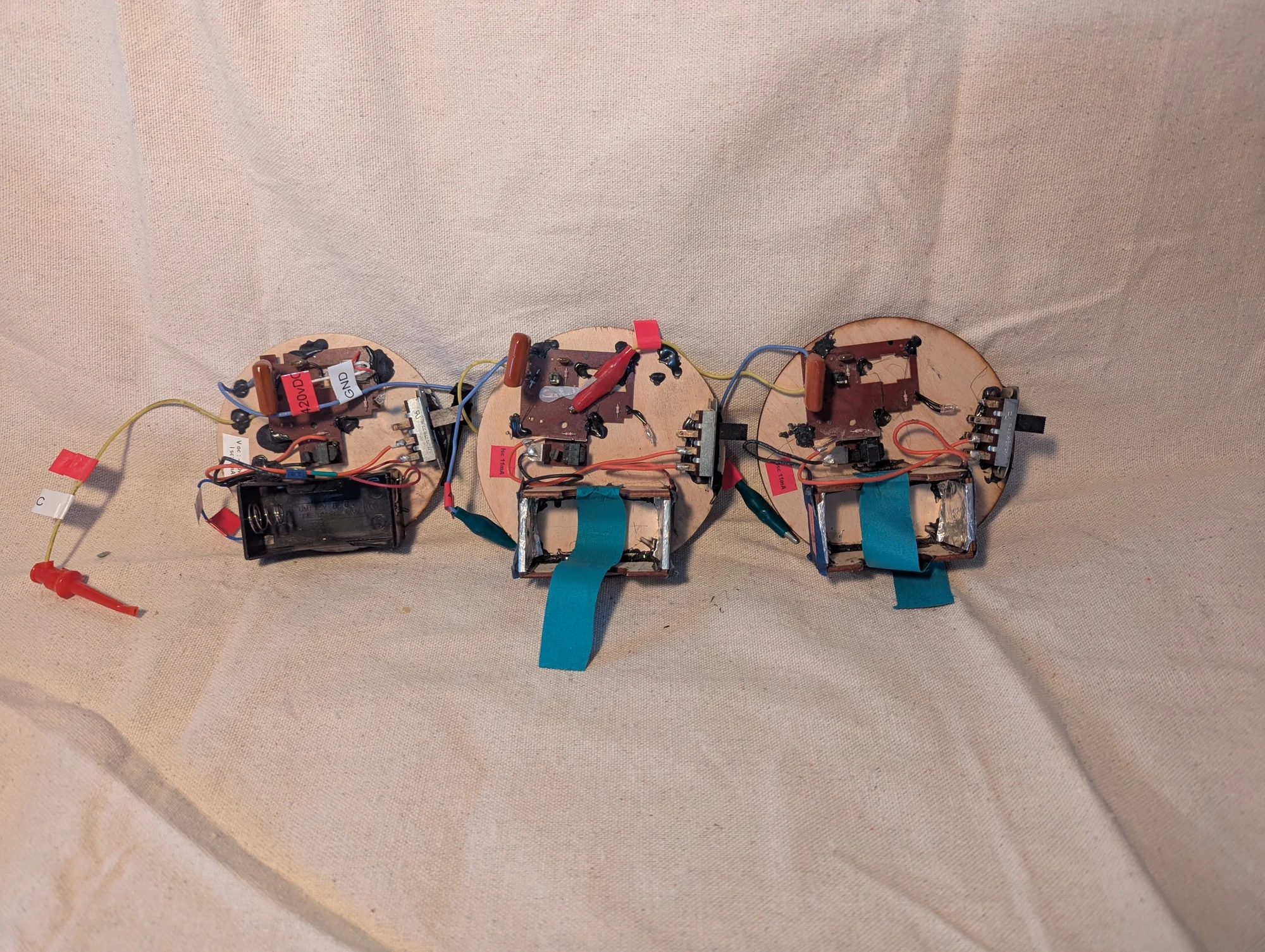
Camera-flash charging circuits mounted on small pieces of wood for early electronics experiments. The wooden bases made the separate assemblies easier to handle on the bench. I adapted them for larger batteries so they could run longer. I no longer use these assemblies; later projects use dedicated voltage modules.
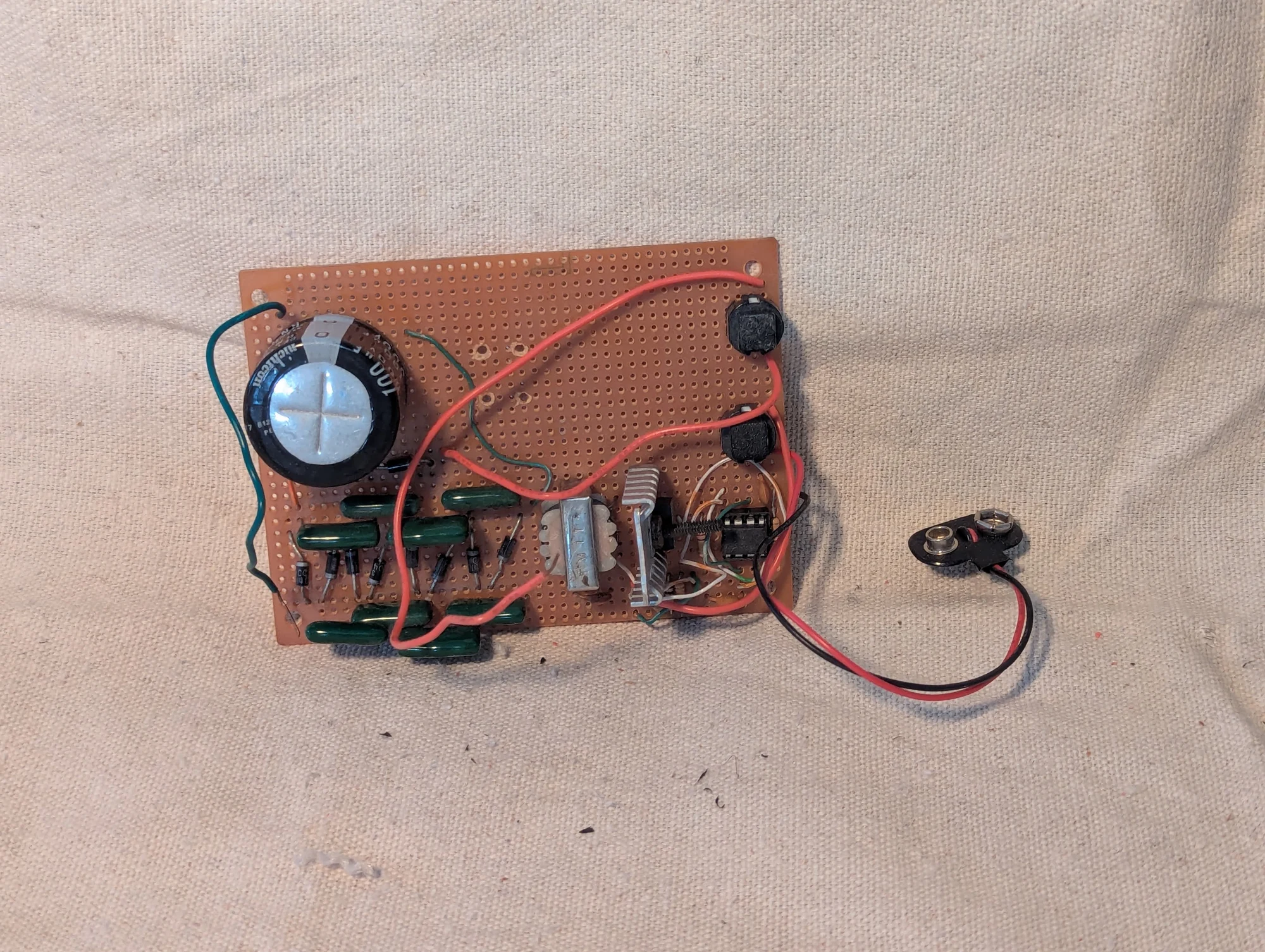
A voltage-multiplier circuit with a large capacitor, built in an electronics lab at Lehigh University during 2011–2015. I frequently visited the lab to work on projects. I no longer recall the exact application of this particular circuit.
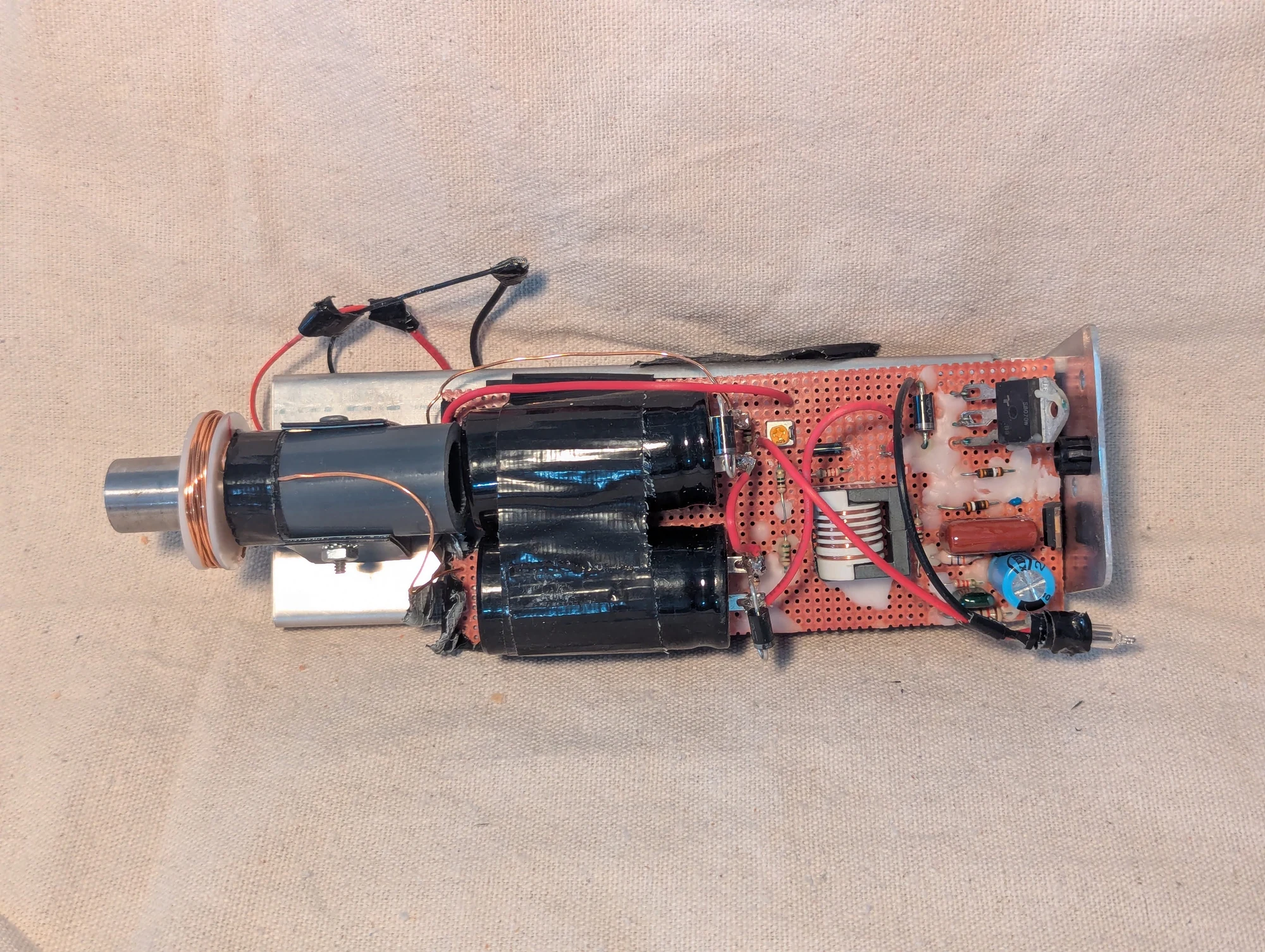
A kit I bought and assembled for an aluminum-washer experiment, probably while I was in high school. I only used it a few times, but assembling it was a useful learning experience.
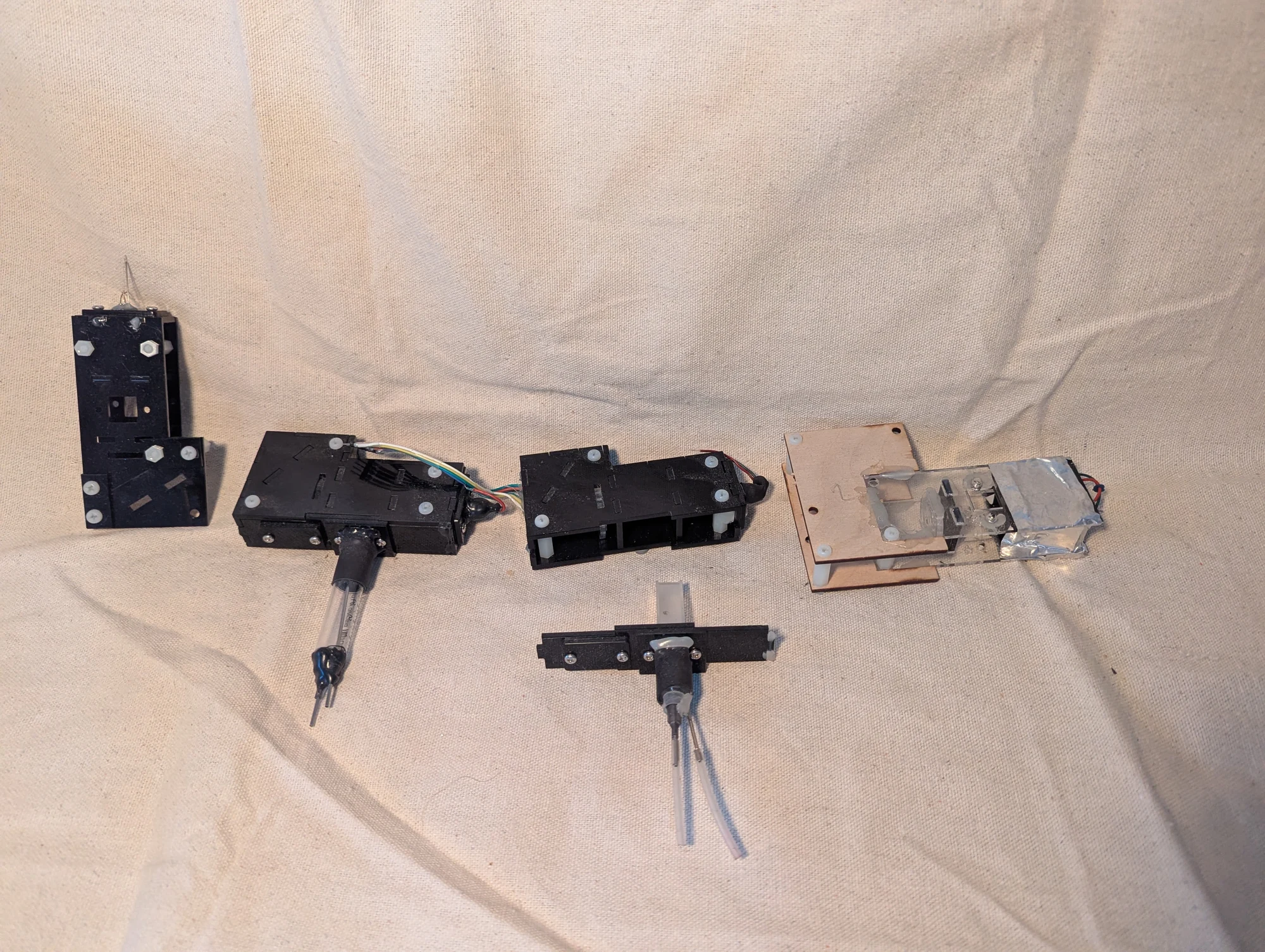
Several attempts at measuring which colors of light pass through a water sample and which are absorbed. I worked on the light source, detection, and repeatable automatic movement of samples. The designs used quartz cuvettes, small optical sample cells, a tungsten lamp, a diffraction grating to separate the colors, and a linear photodiode array, a row of light-sensitive detectors.
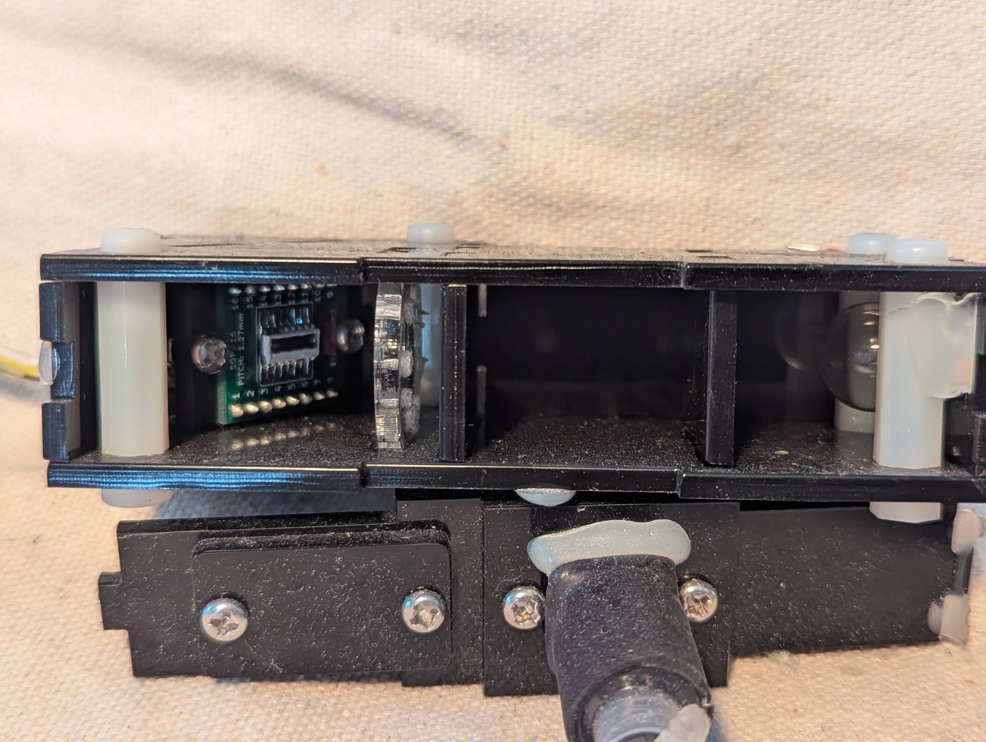
An opened prototype showing more of the optical layout. A diffraction grating separated the light by color, and a row of photodiodes was intended to measure the transmitted spectrum, revealing which parts of the light were absorbed by the water sample.
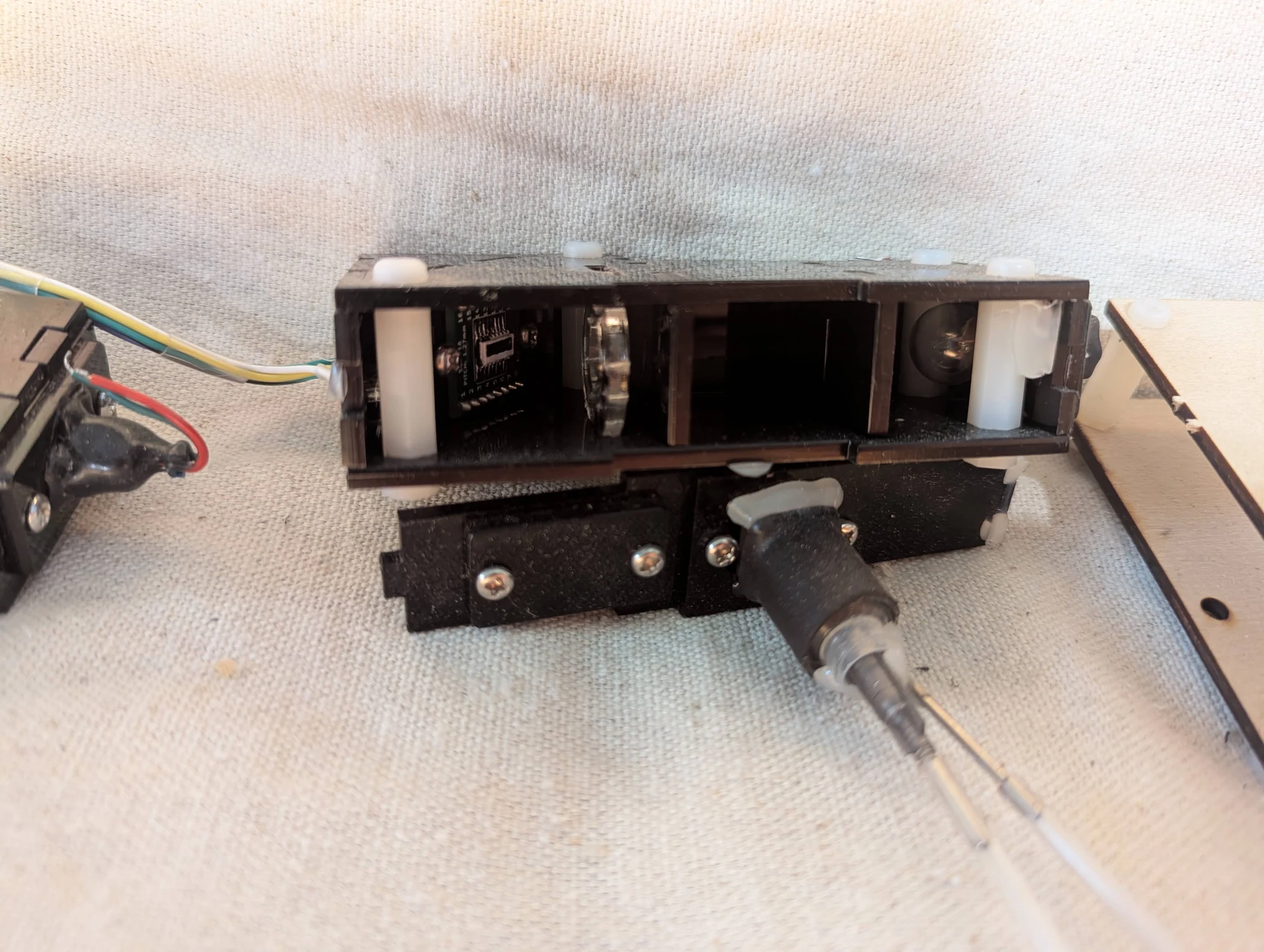
Another view of the water-sample measurement prototype. The project brought together illumination, optical detection, and ways to move samples through the instrument repeatedly.
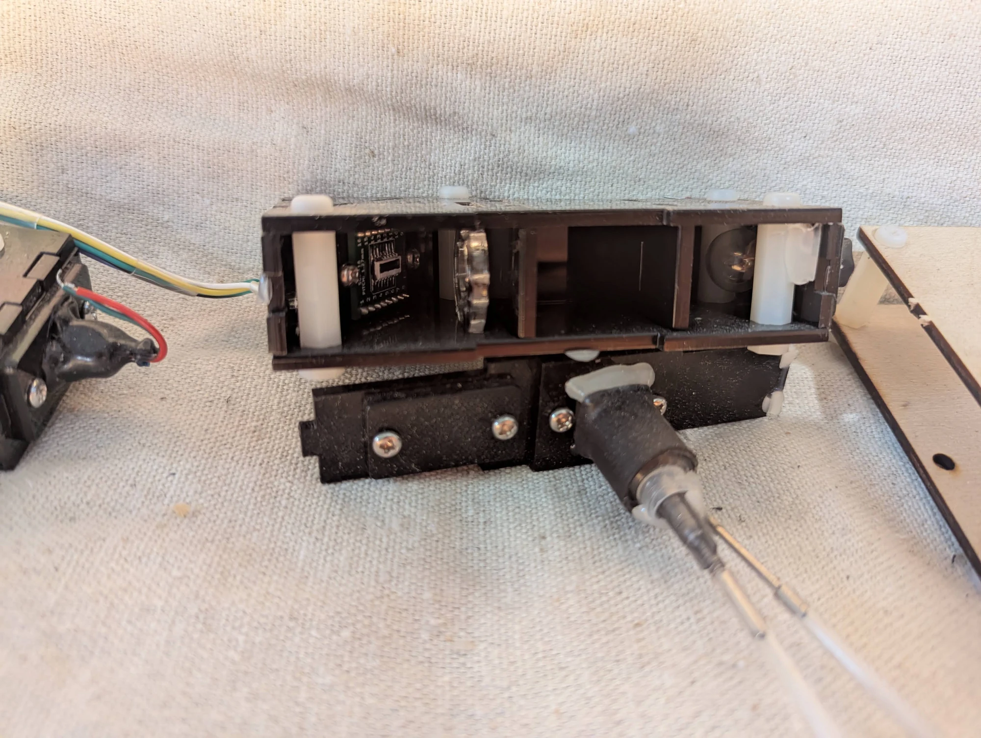
A further angle on the optical measurement assembly, showing the arrangement of parts used to investigate light transmission through water samples.
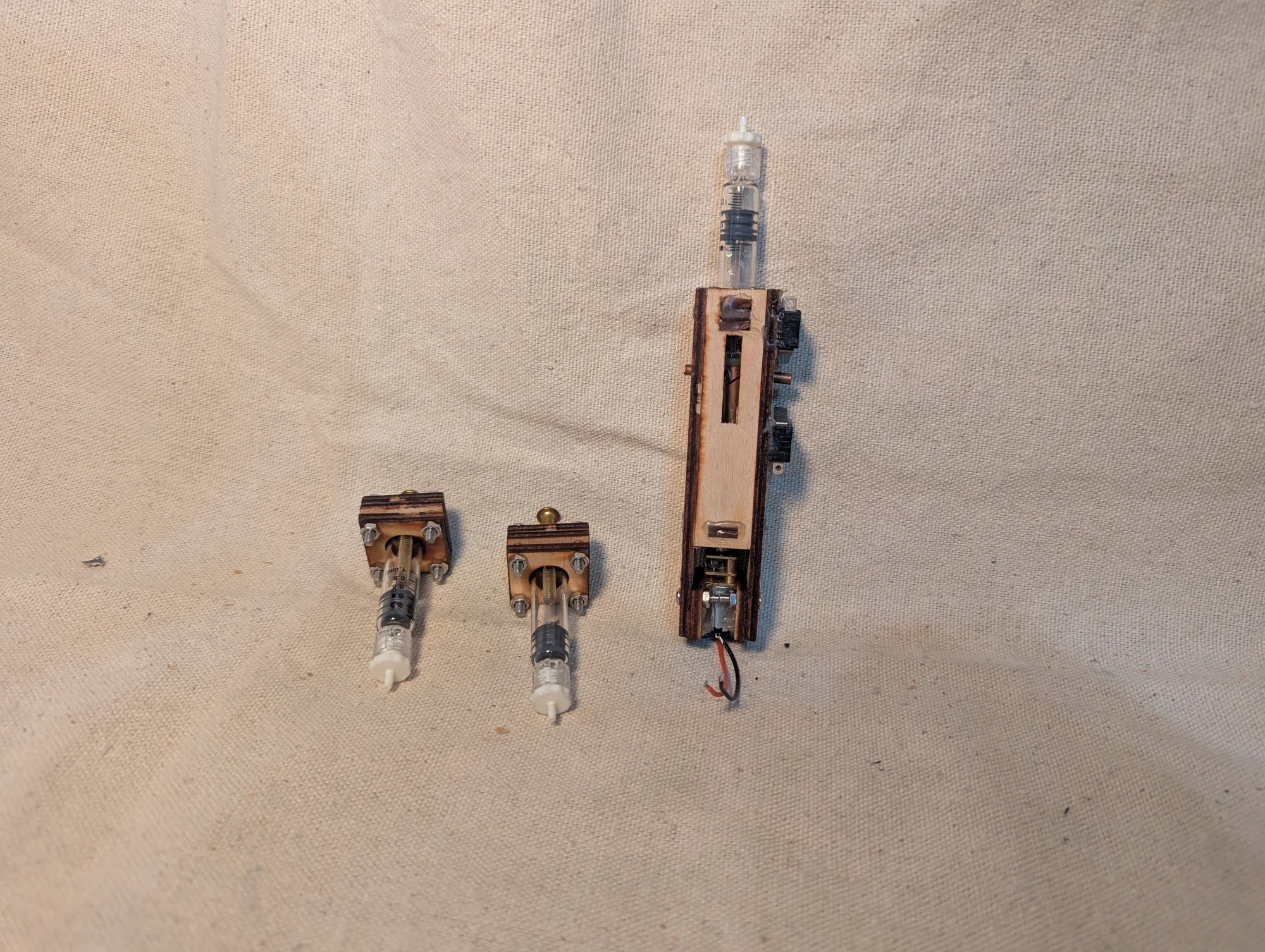
Syringe mechanisms from my microfluidics experiments, which involved small amounts of liquid. The two smaller syringes have screw-adjustable stops to change the plunger position and available volume. The larger mechanism uses a motor-driven screw to move the plunger, with limit switches at the ends of its travel.
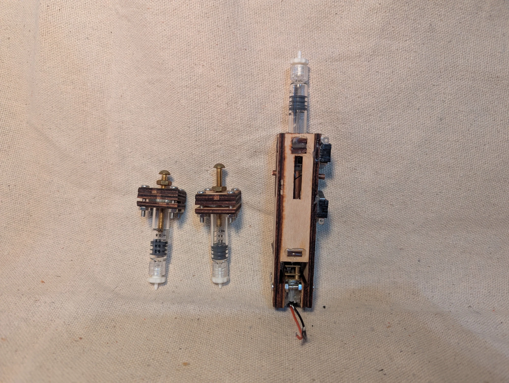
Another view of the two manually adjustable syringe stops and the motor-driven syringe mechanism. I no longer recall the exact microfluidic experiment these supported.
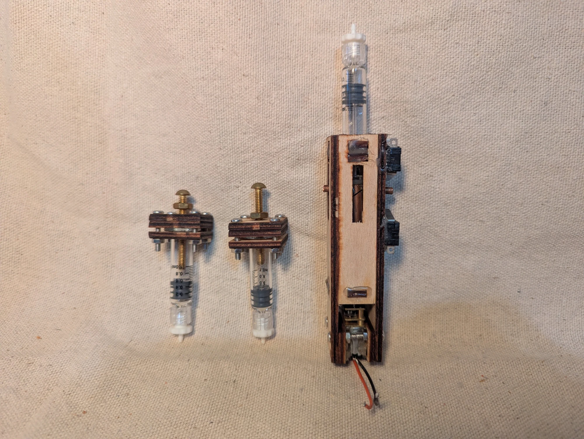
A further view of the syringe mechanisms: screw-adjustable stops on the smaller syringes, alongside the powered plunger mechanism and its travel-limit switches.
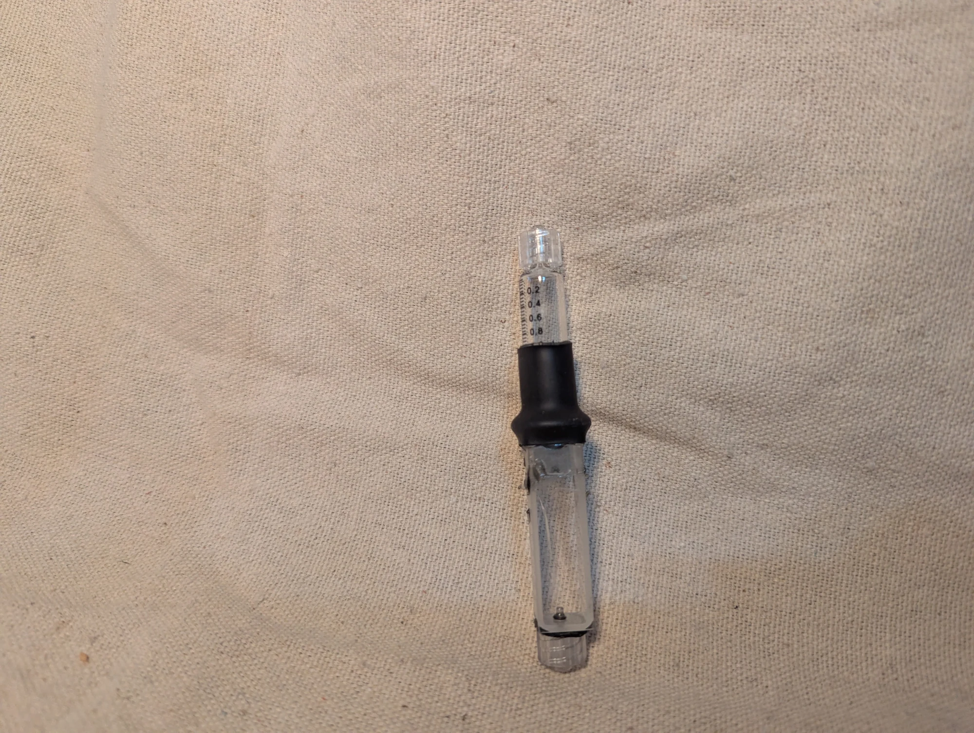
A syringe attached to an optical cuvette, the small transparent cell that holds a water sample for light measurements. This was part of the water-spectroscopy project. I do not recall whether this particular cuvette was glass or quartz.
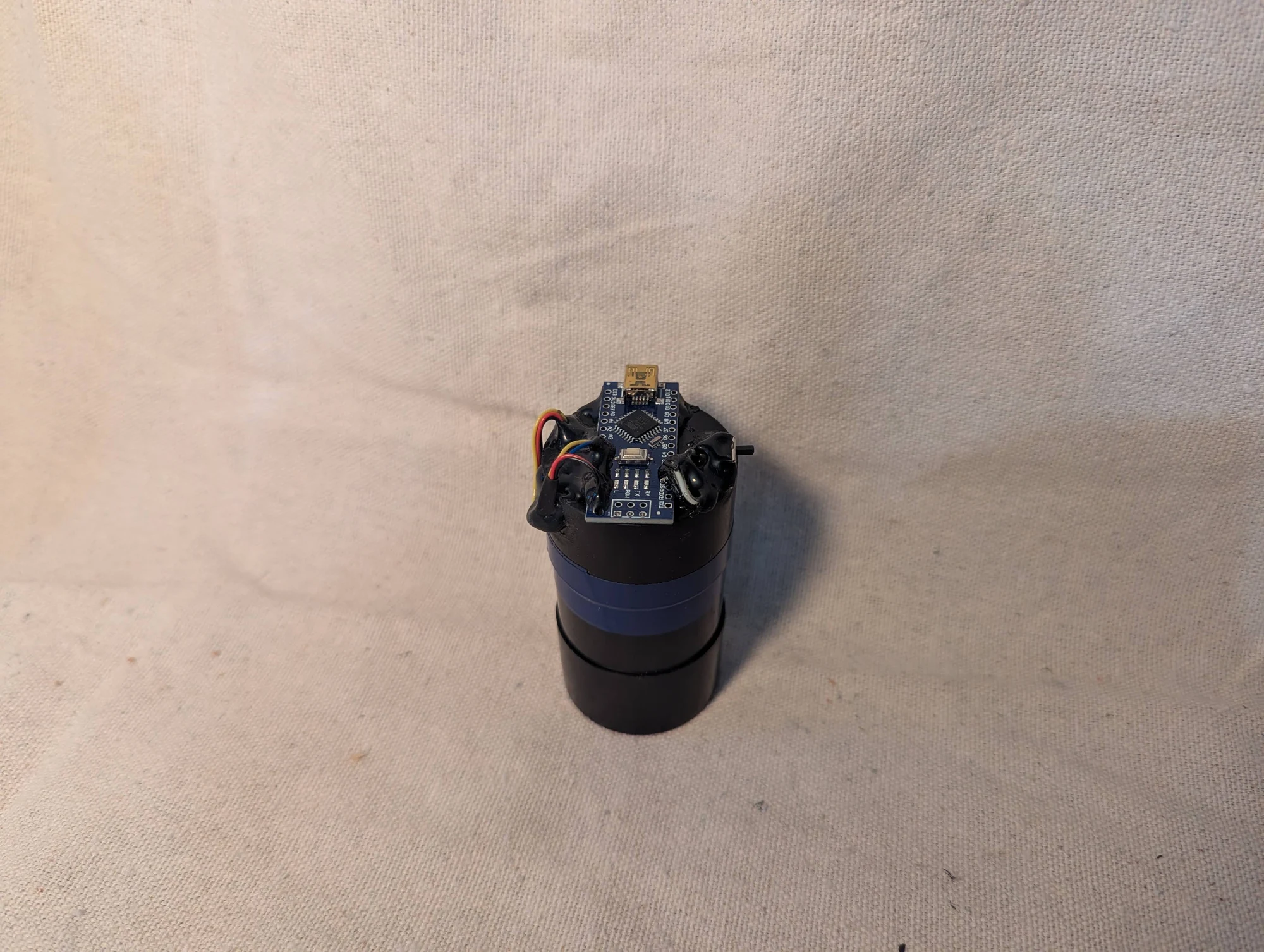
A simple reflected-color measurement experiment built around an Arduino Nano and a sensor module with color-selective optical filters. It collected readings for different color bands, including infrared, so I could plot an object's reflected light. I only used this experimental assembly a few times.
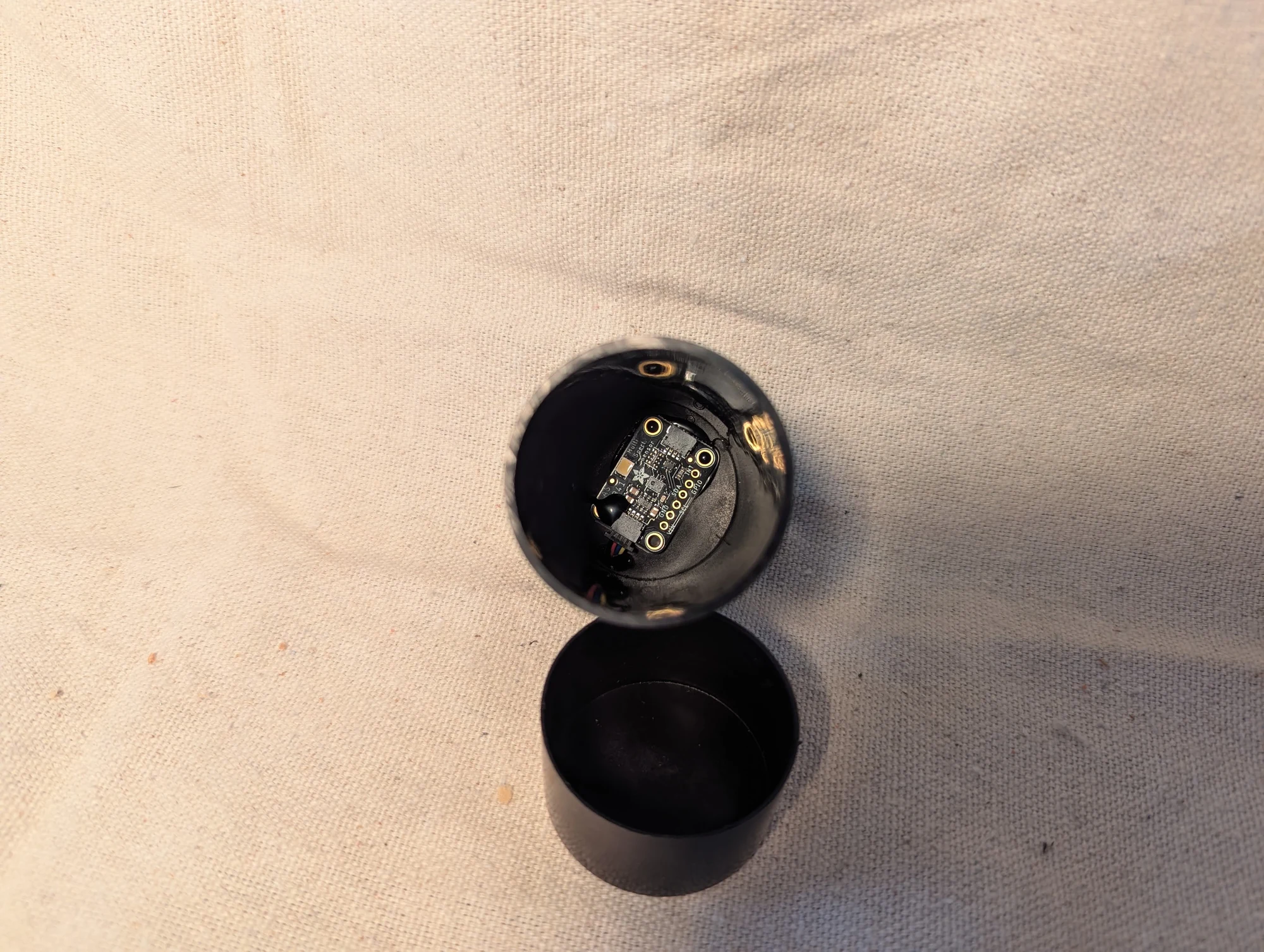
Another view of the reflected-color experiment, with the housing opened to show the sensor assembly. The Arduino-based setup was used to explore readings from different color bands.
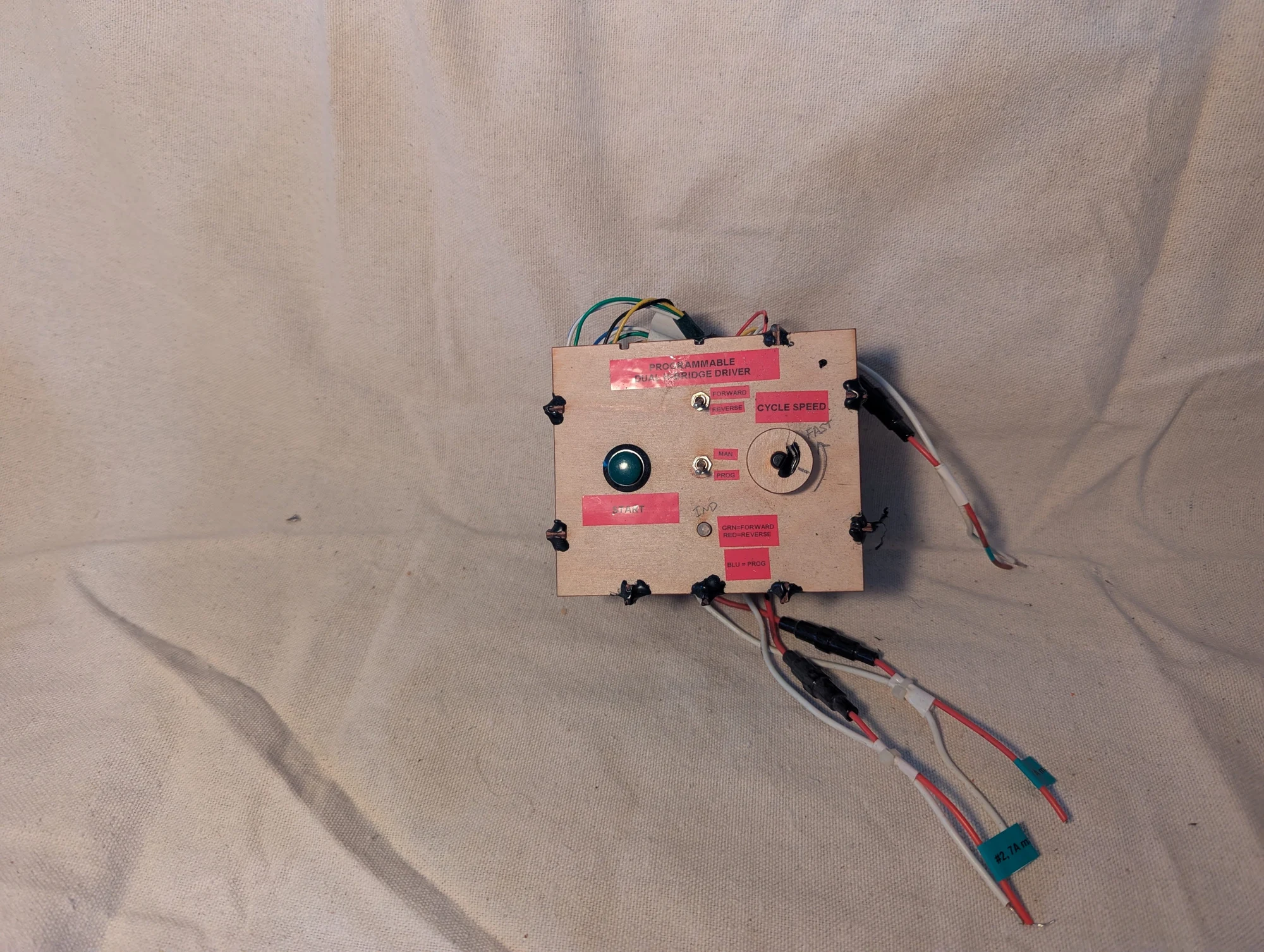
A controller for an experimental ferrofluid pump. Ferrofluid is a liquid that responds to a magnetic field. The controller drove four coils around a cylindrical magnet, changing the fields to make it rotate. The rotating magnet pulled segments of ferrofluid, separated by air bubbles, along a tube wrapped around it.
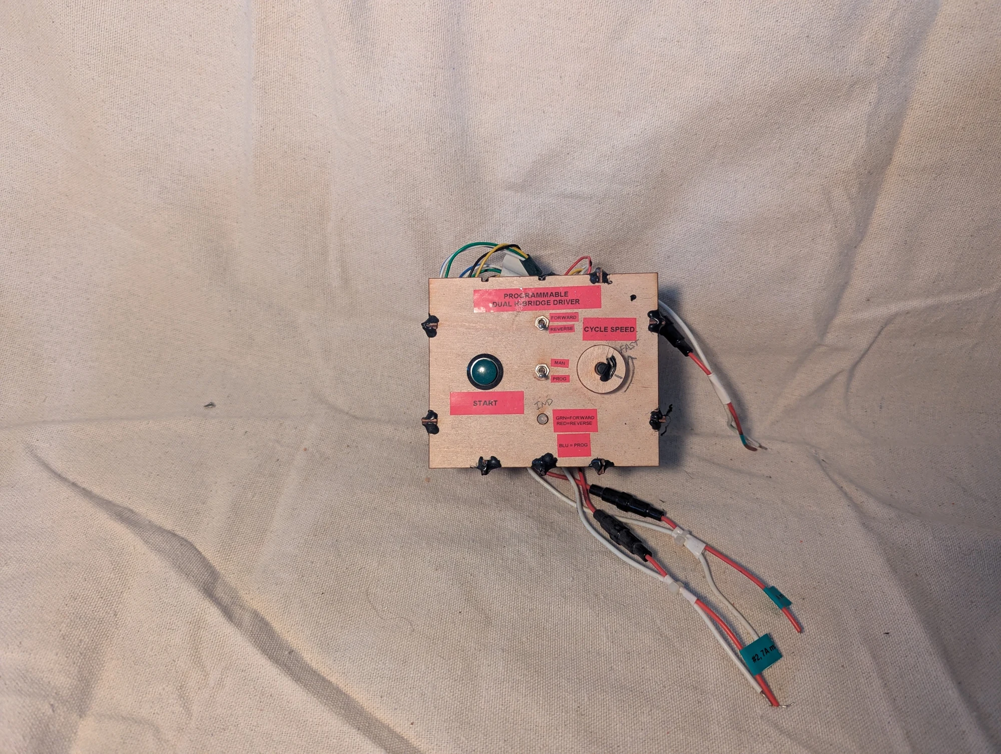
Another view of the controller for the rotating-magnet ferrofluid pump. It coordinated the coils that turned the central magnet, moving alternating segments of magnetic liquid and air through the tubing.
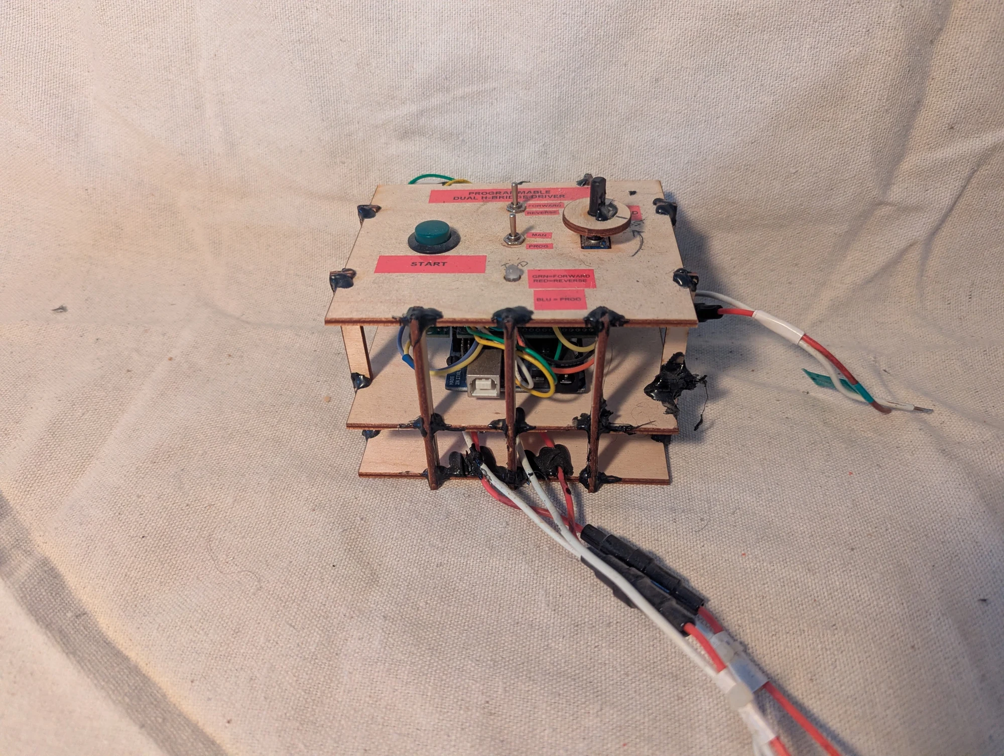
An additional view of the pump-control hardware and wiring. This controller was part of the experiment in moving ferrofluid through tubing using a rotating magnetic field.
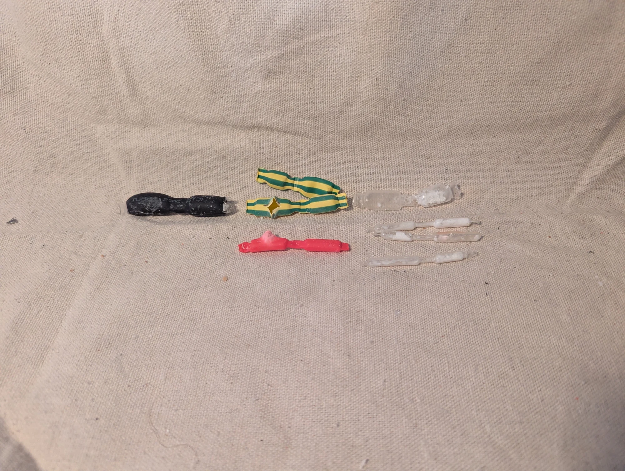
Small chemistry-and-materials experiments exploring gas generation and sudden pressure release in flexible tubing. These were exploratory samples made to observe how the material responded.
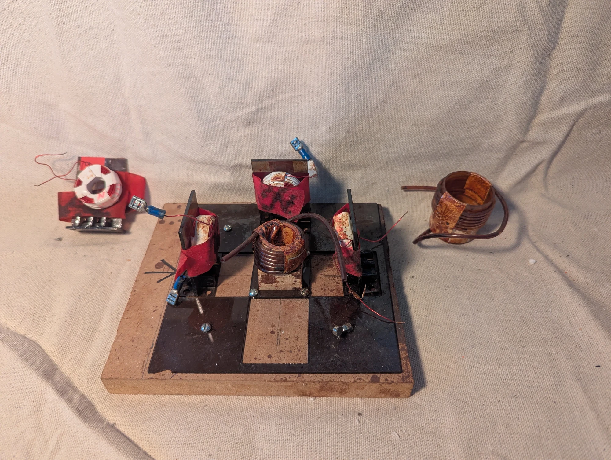
The pump mechanism described in Photos 321–323. Four coils surrounded a cylindrical magnet with its poles on opposite sides of the cylinder. As the magnet rotated, it drew alternating segments of ferrofluid and air along the spiral tube wrapped around it. This was part of my early Fernbrake experiments.
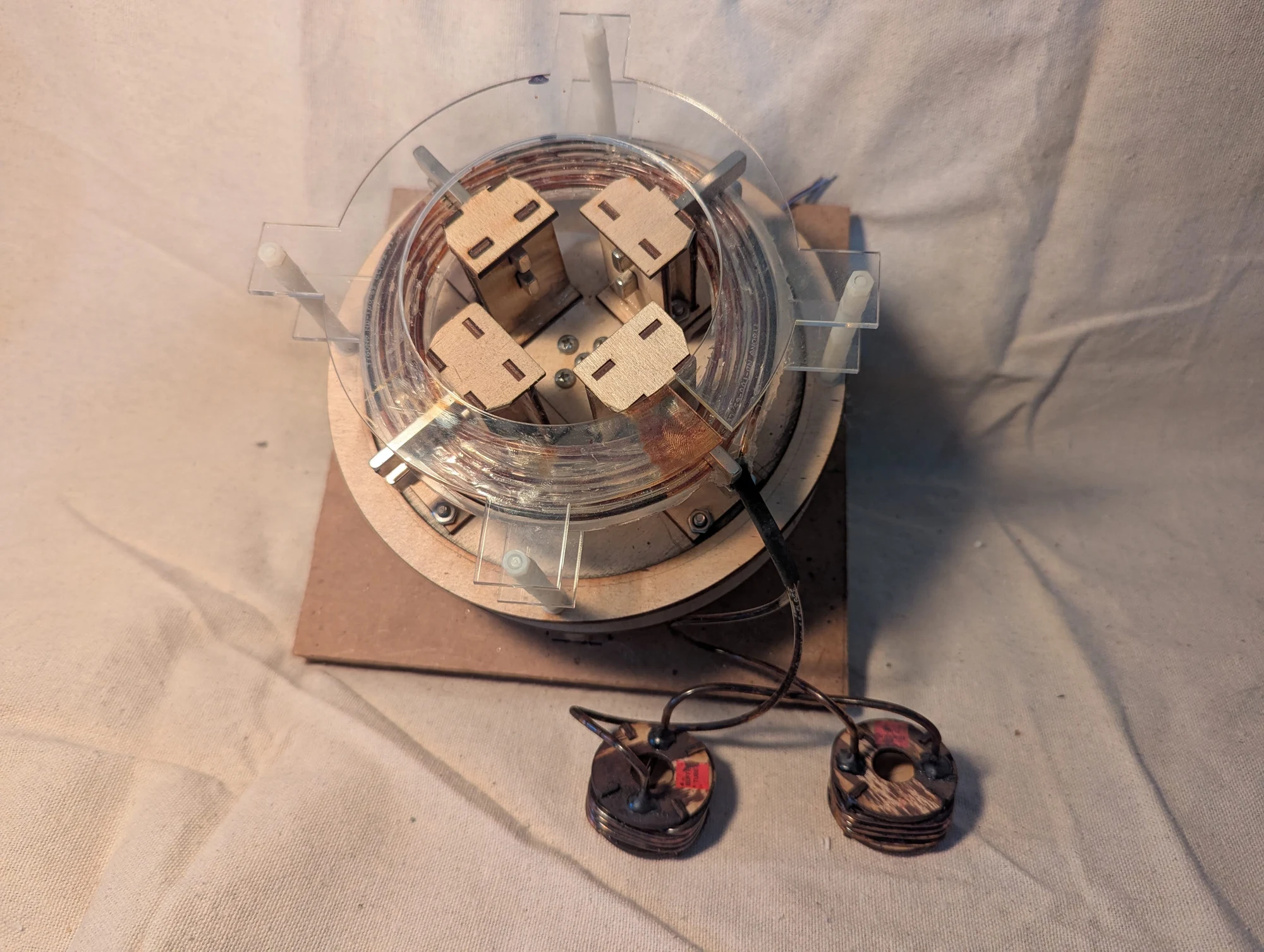
Another ferrofluid-pump experiment, with flexible tubing arranged in a flat spiral and containing segments of magnetic liquid separated by air bubbles. Four rotating magnets were intended to pull the ferrofluid around the tubing and toward the outlet.
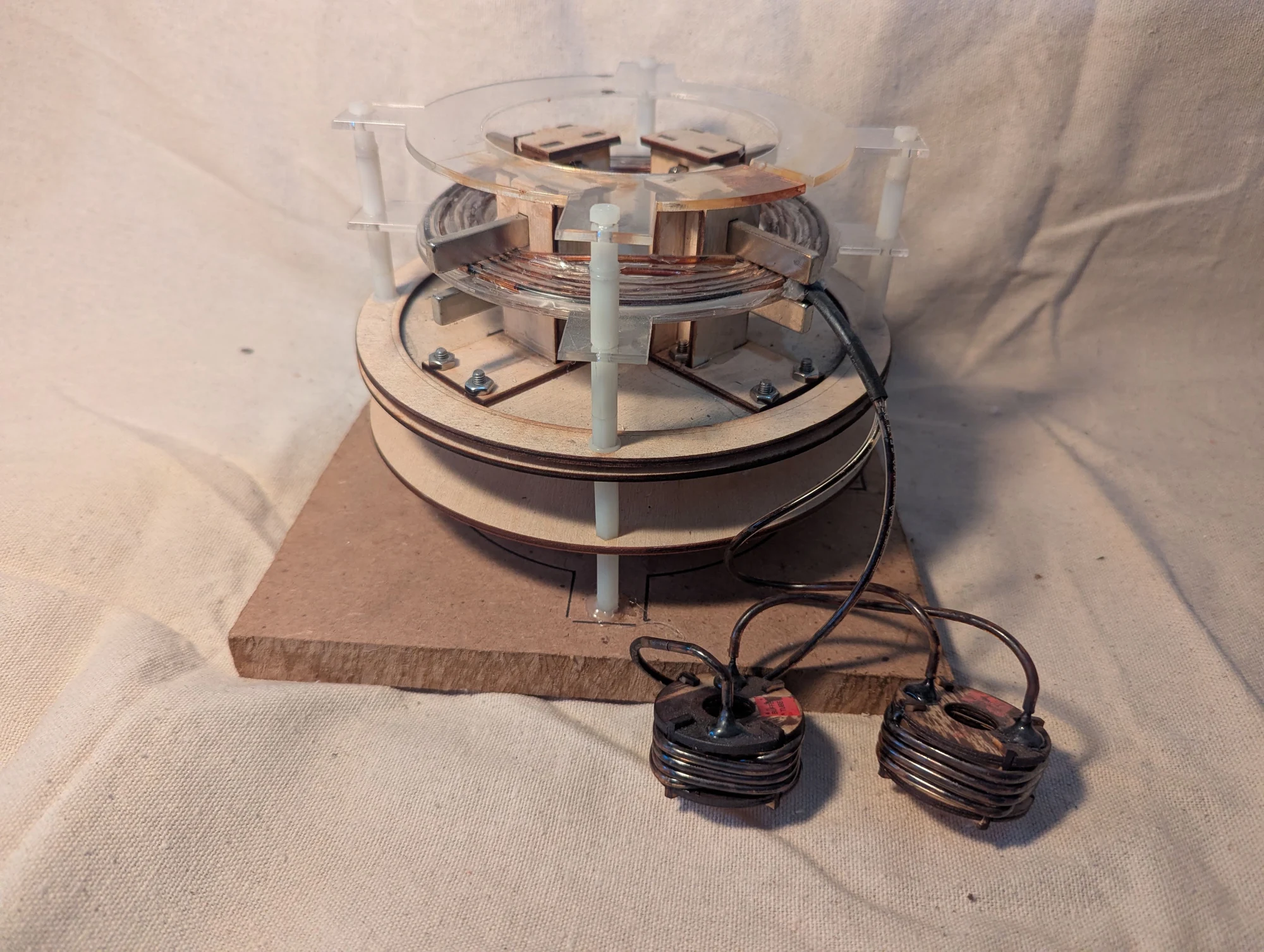
A second view of the flat-spiral ferrofluid pump, showing the tubing and rotating-magnet mechanism used to move the magnetic liquid.
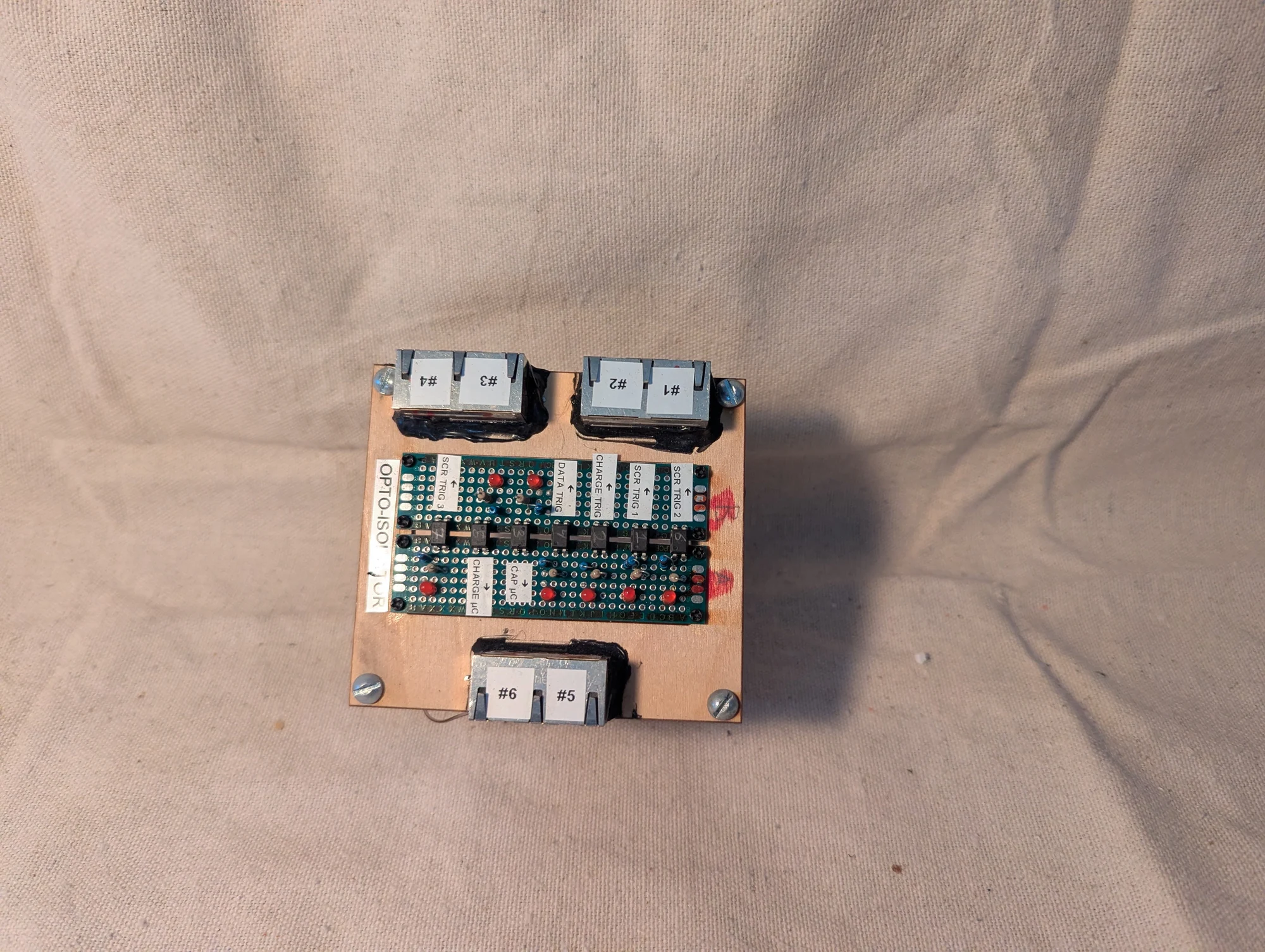
An optoisolator board I made for Fernbrake's magnetic-refrigeration project. Optoisolators pass signals using light, keeping the controller electrically separate from the high-power circuitry. I used network-style sockets because I had them on hand; they carried simple on/off control signals, with no Ethernet communication involved.
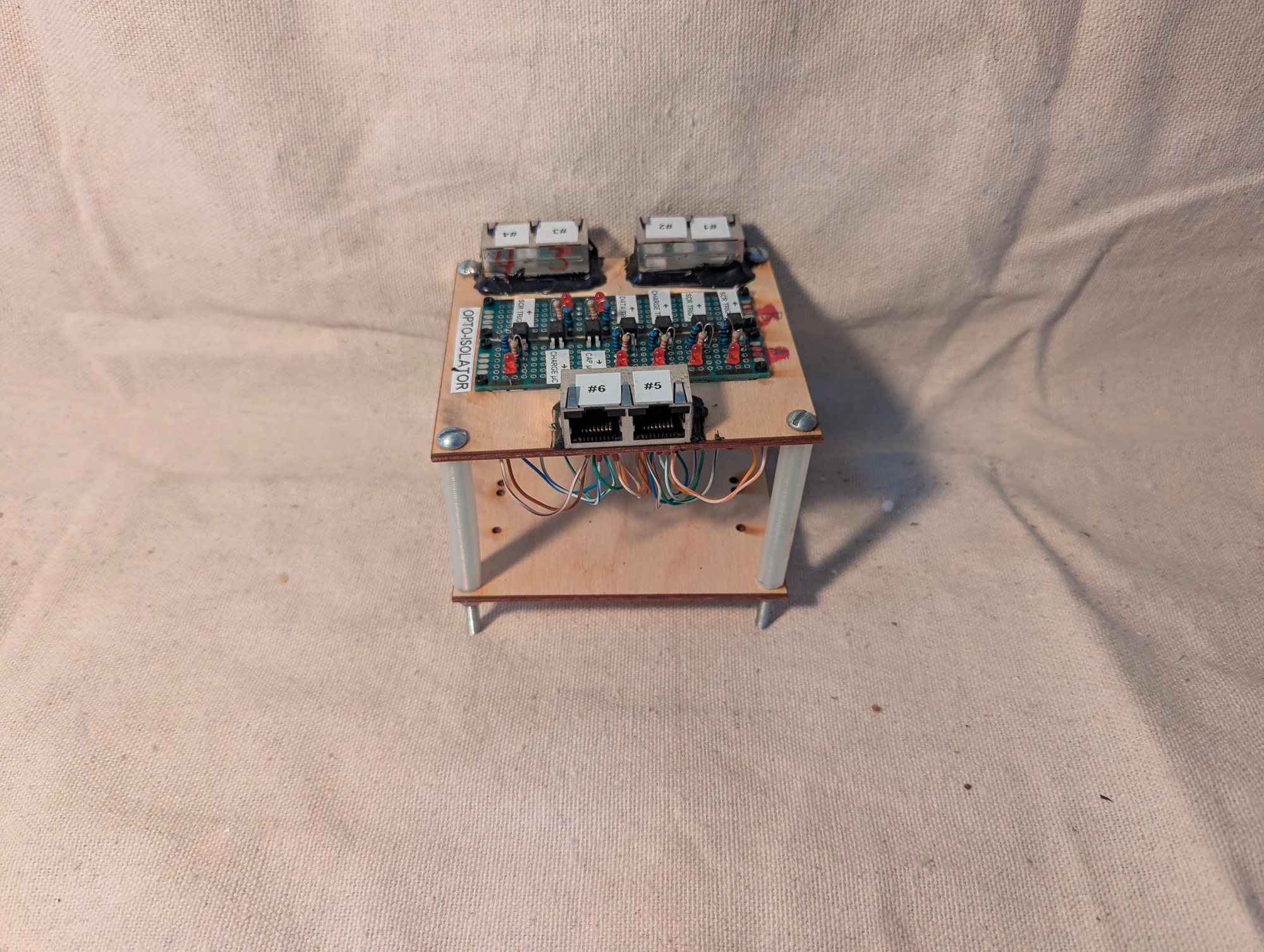
A second view of the optoisolator board and its connectors. Its role was to pass control signals between electrically separate sections of the magnetic-refrigeration apparatus.
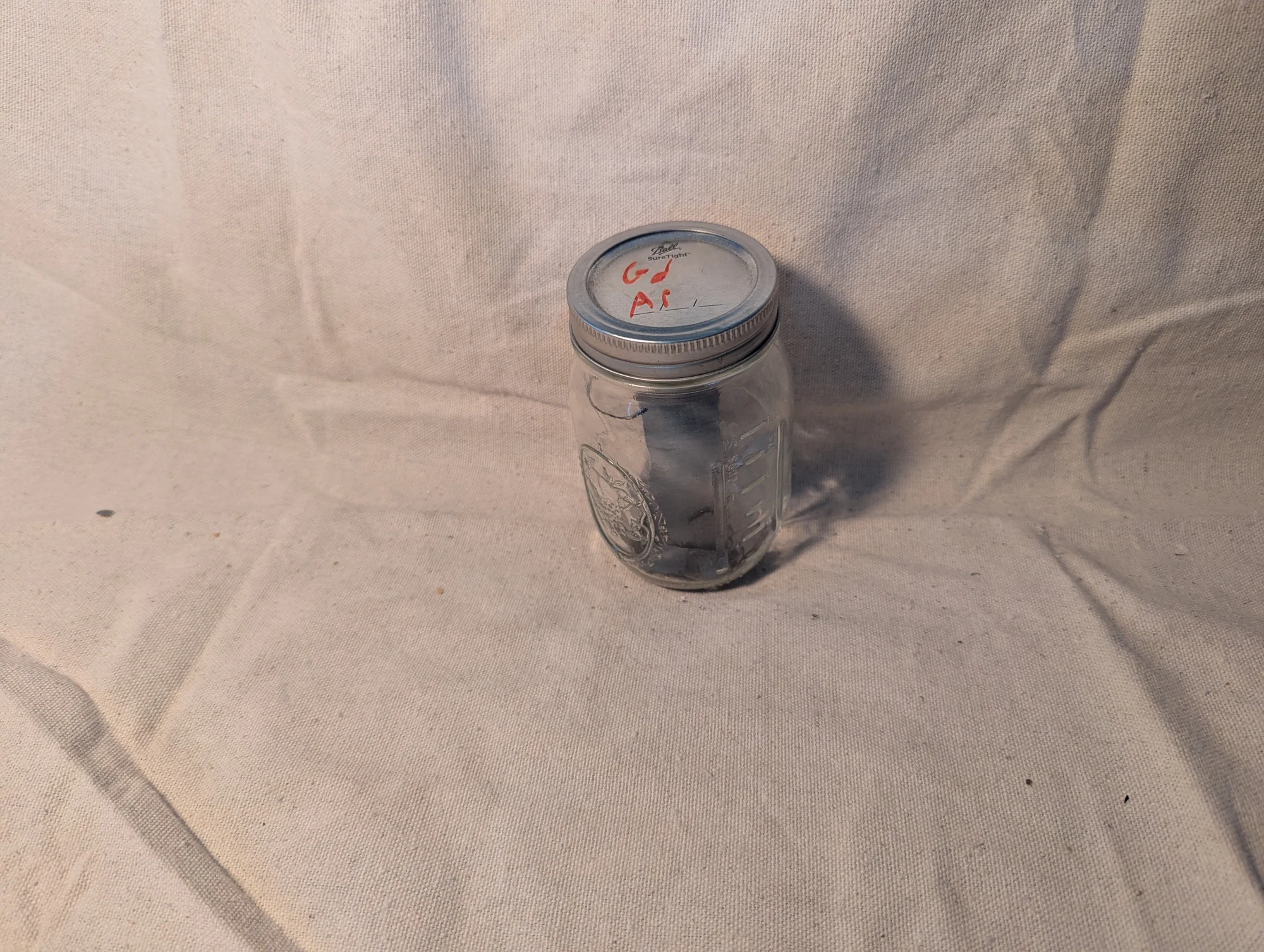
Gadolinium sheets stored in an argon atmosphere. I purchased a batch of this material for Fernbrake's magnetic-refrigeration experiments.
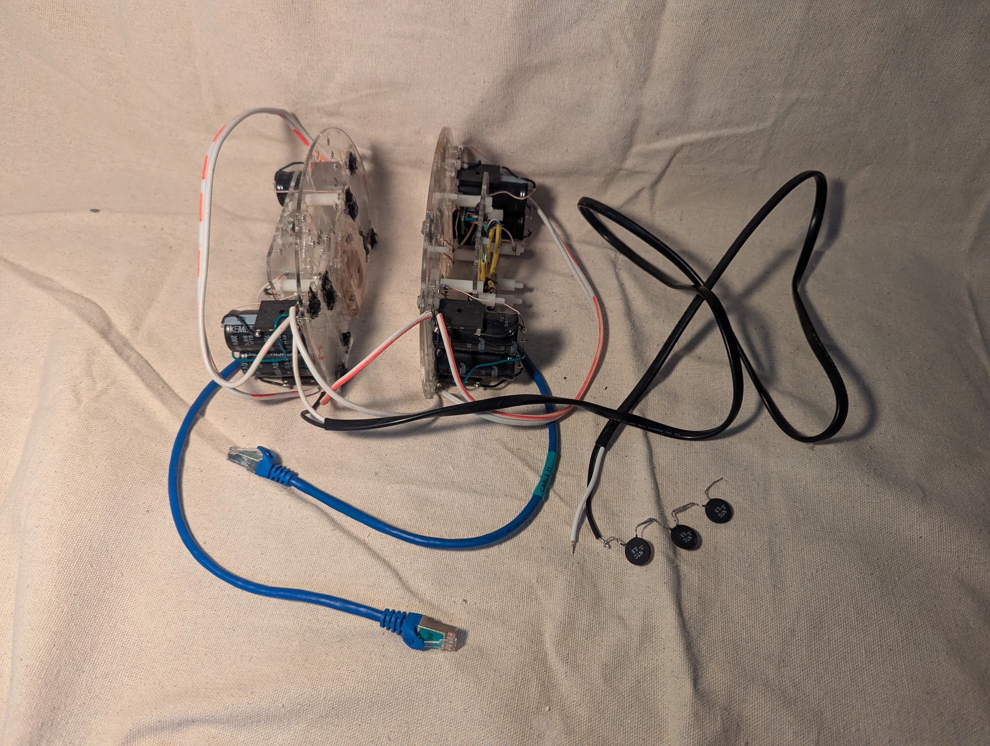
An experimental assembly from my Fernbrake magnetic-refrigeration work. Flat coils of litz wire sat on either side of a gadolinium sheet, with capacitor banks supplying brief bursts of electrical energy. I was exploring the magnetocaloric effect, a change in a material's temperature associated with a changing magnetic field. I later questioned whether magnetic losses and limited heat transfer would make this approach practical.
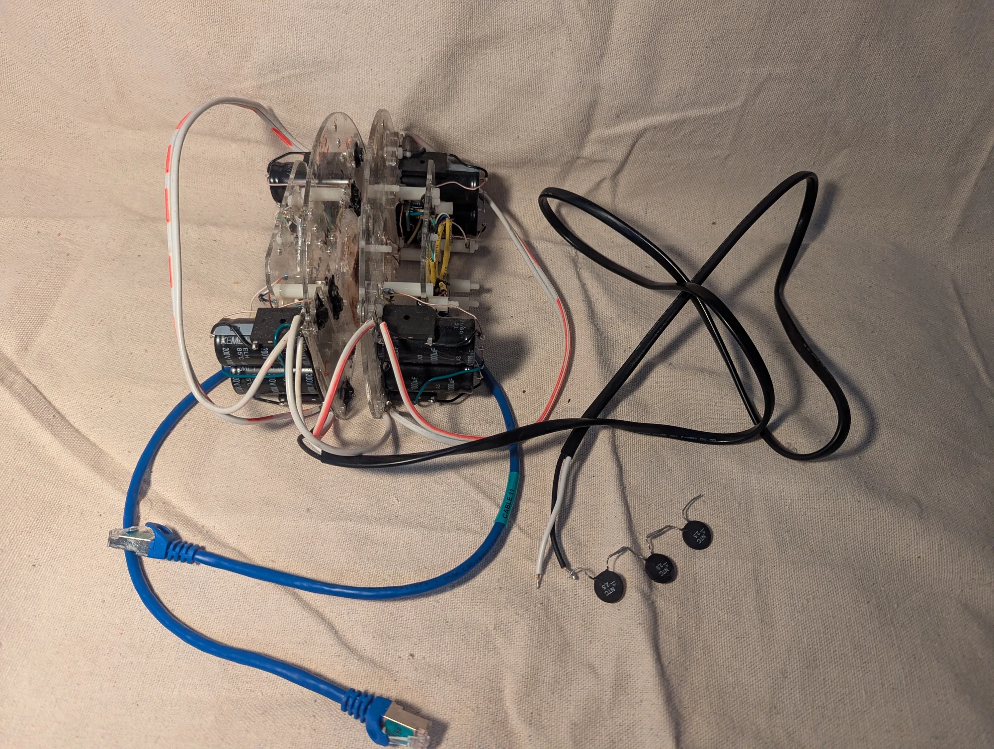
The two sides of the pulsed-field assembly positioned around the central plates. The experiment was intended to expose the gadolinium to brief magnetic-field changes as part of the cooling research.
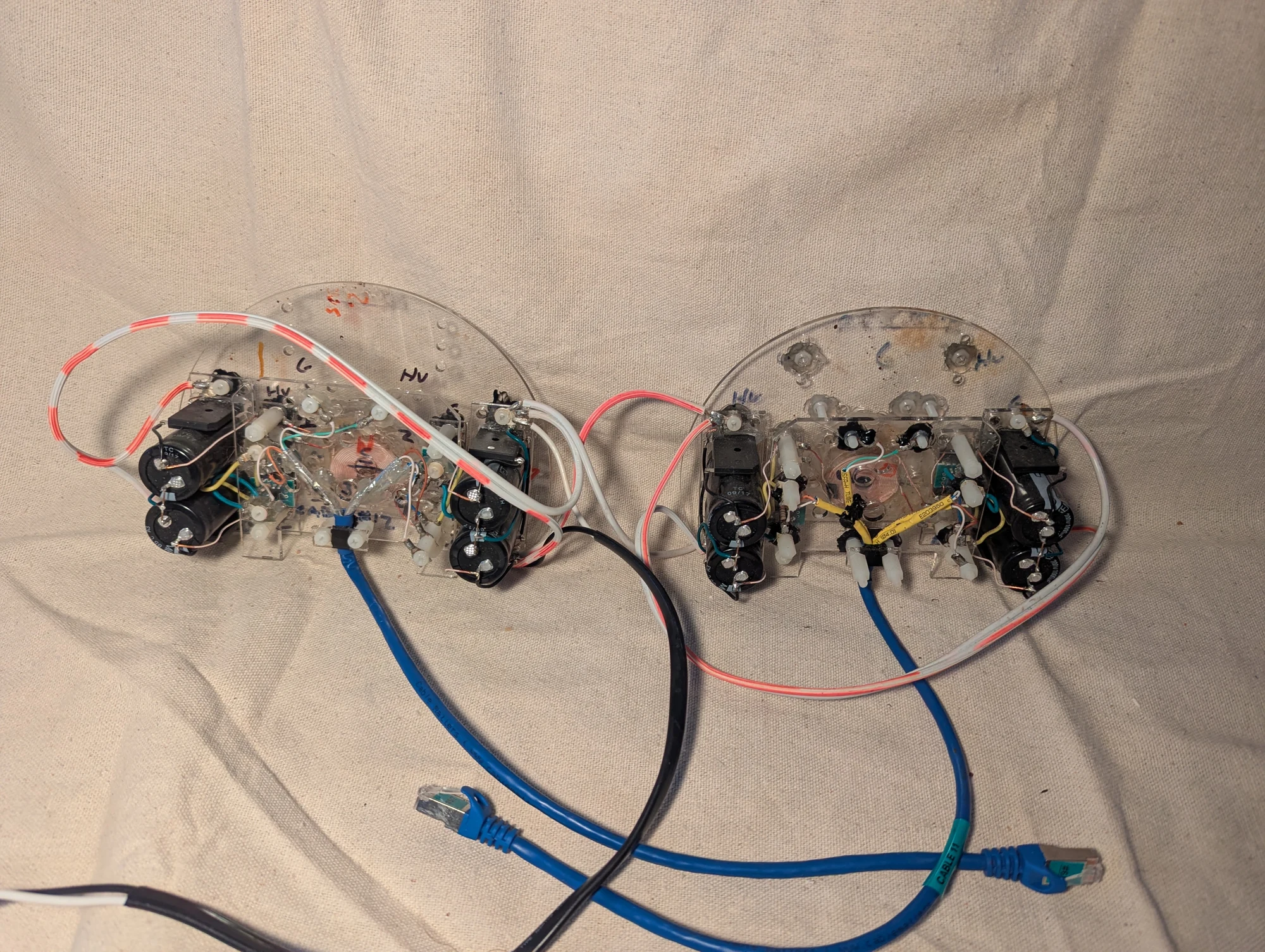
The assembly opened to show the flat litz-wire coils in the center and the capacitor banks beside them. Network-style cables provided convenient connections for the triggering controls; they were used as ordinary control wiring.
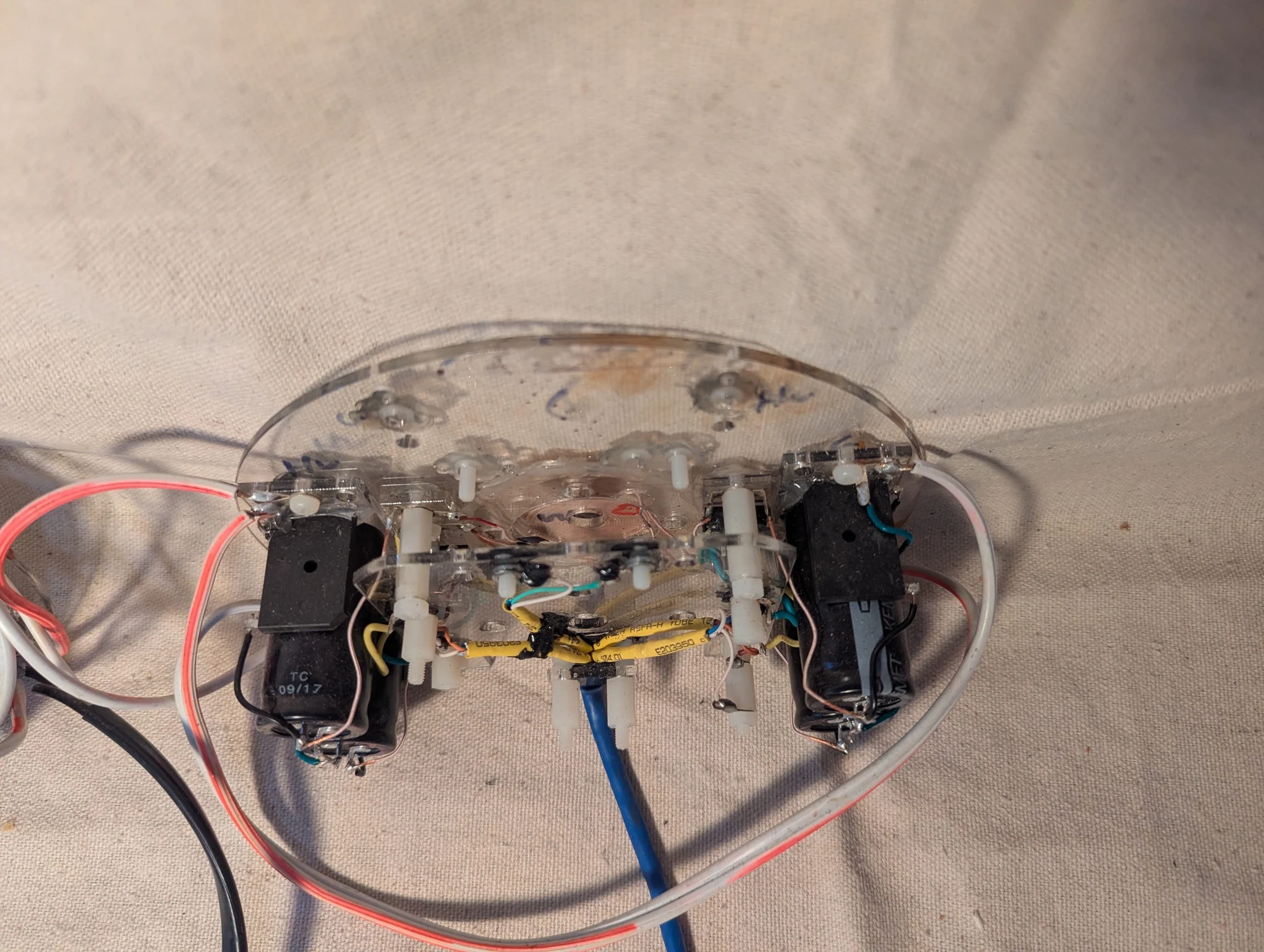
Another view of one half of the magnetic-refrigeration experiment, showing the central coil and the surrounding electrical components.
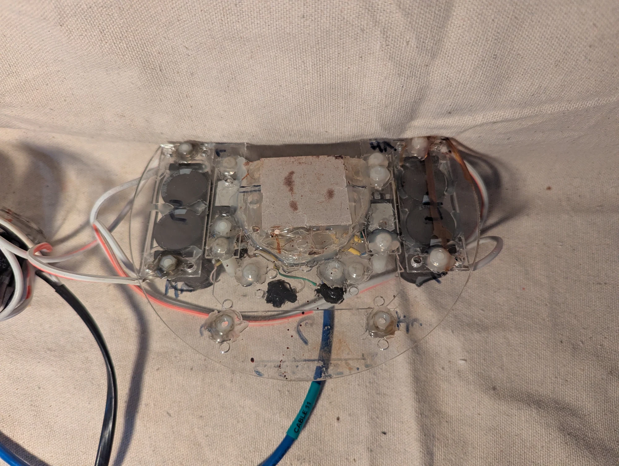
A close view of a thin insulating sheet in front of the flat coil. I recall this sheet being mica, used to provide a thin, nonmagnetic insulating surface.
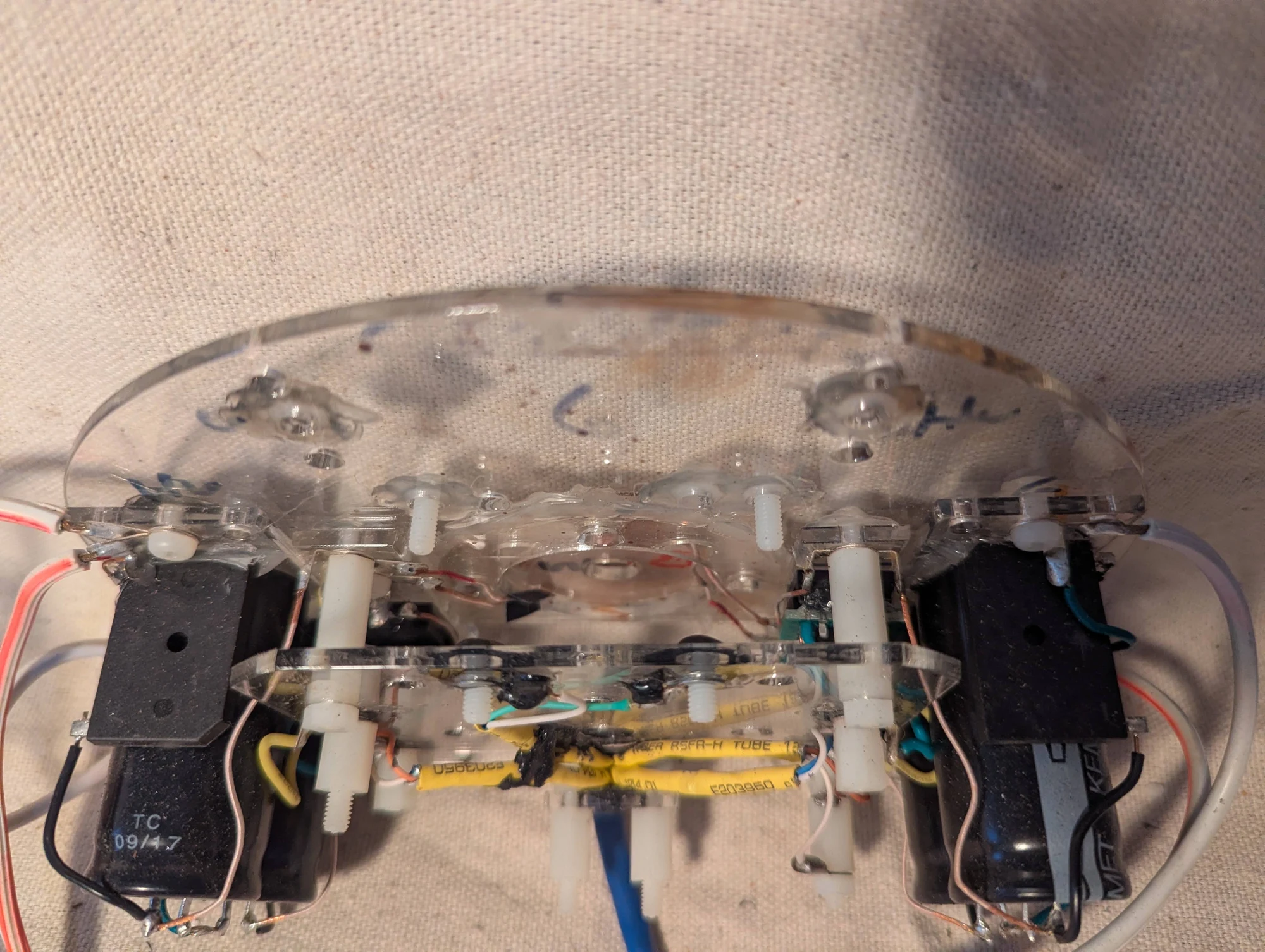
Another angle on the pulsed-field assembly, with the coil, insulating layer, and surrounding components visible.
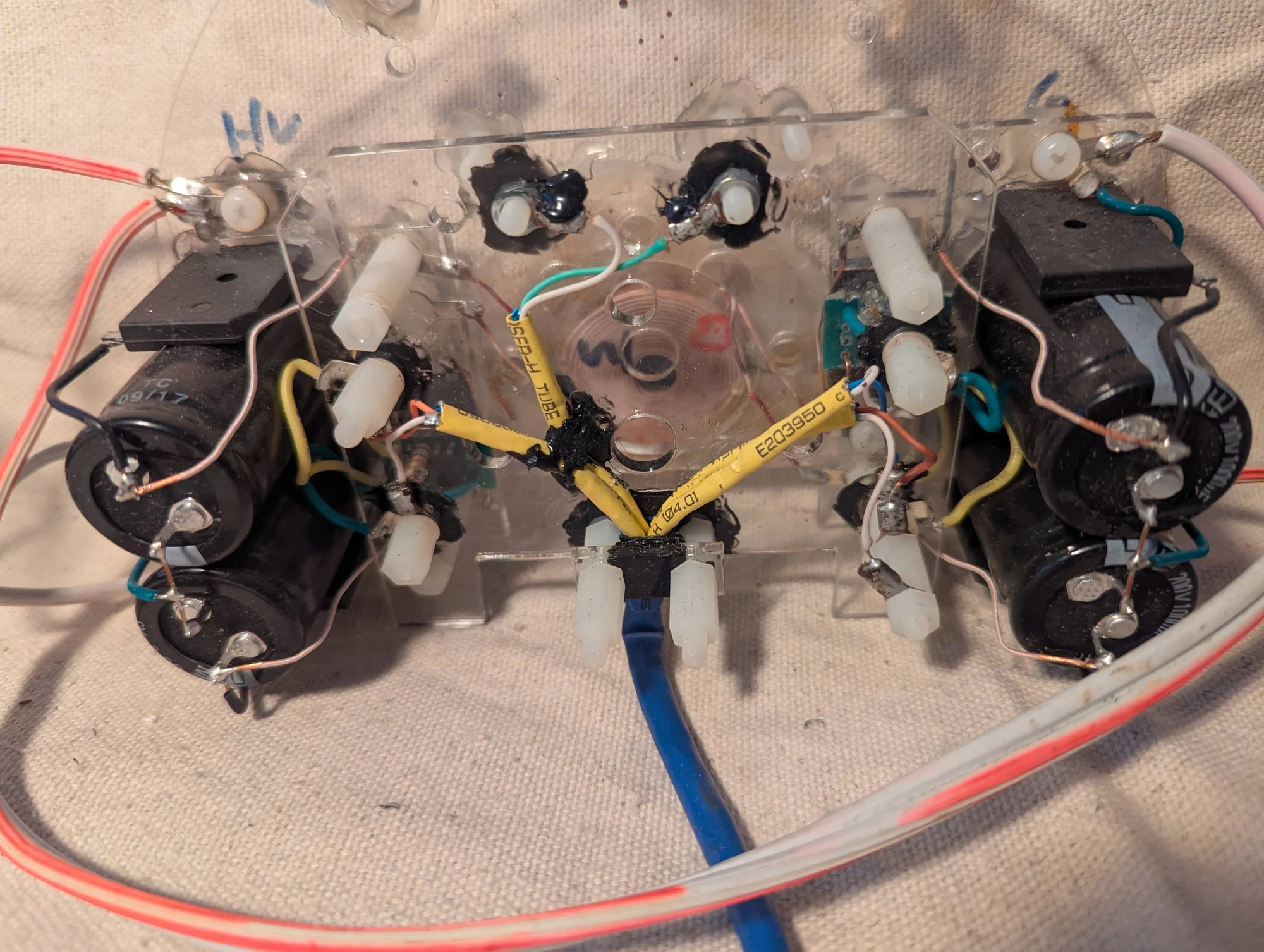
A closer view of the central region of the magnetic-refrigeration apparatus and its surrounding wiring and components.
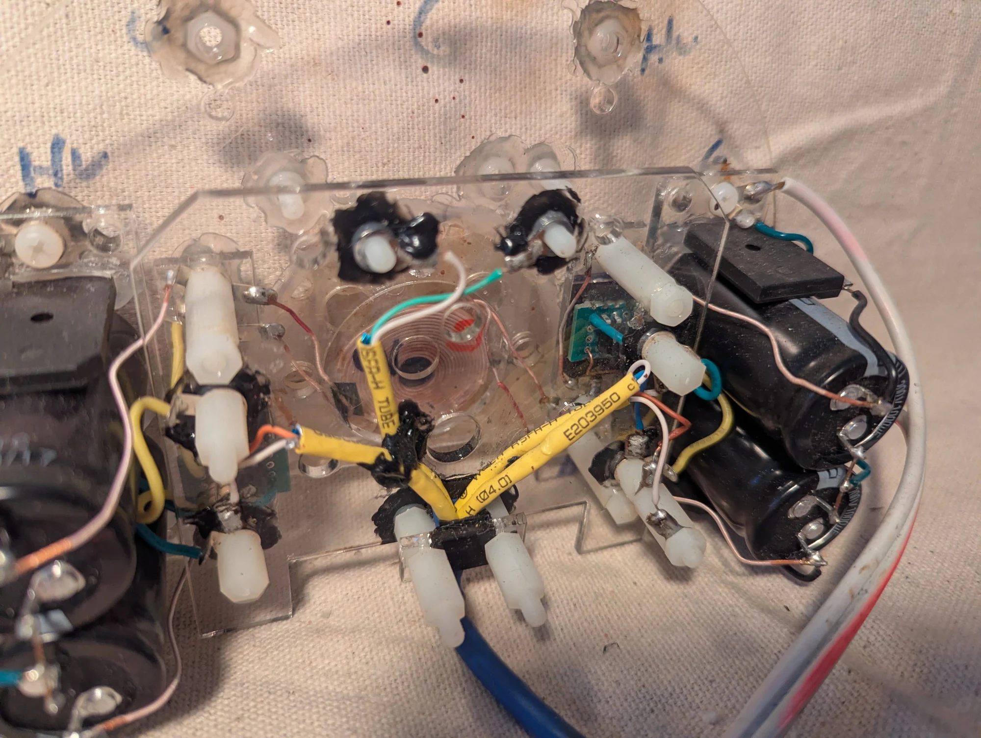
An additional view of the pulsed-field apparatus used in the exploratory magnetic-refrigeration work.
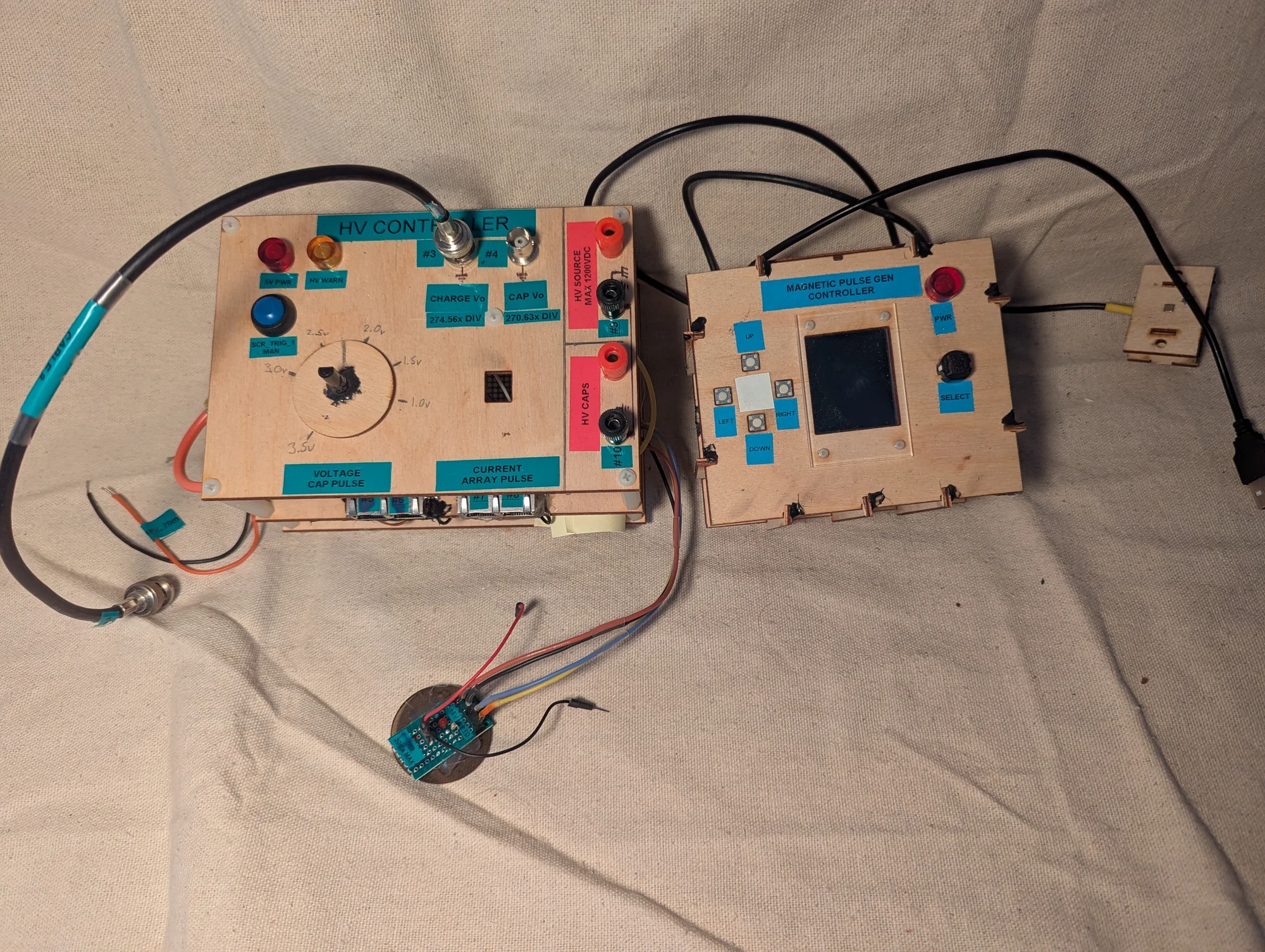
The right-hand box let me choose test programs, pulse patterns, charge/discharge timing, and target voltages. Its screen displayed settings and voltage feedback. The left-hand box managed capacitor charging. I monitored discharge current with a separate current transformer, but do not recall whether current also appeared on the controller's screen. Twisted-pair network cables carried the control connections.
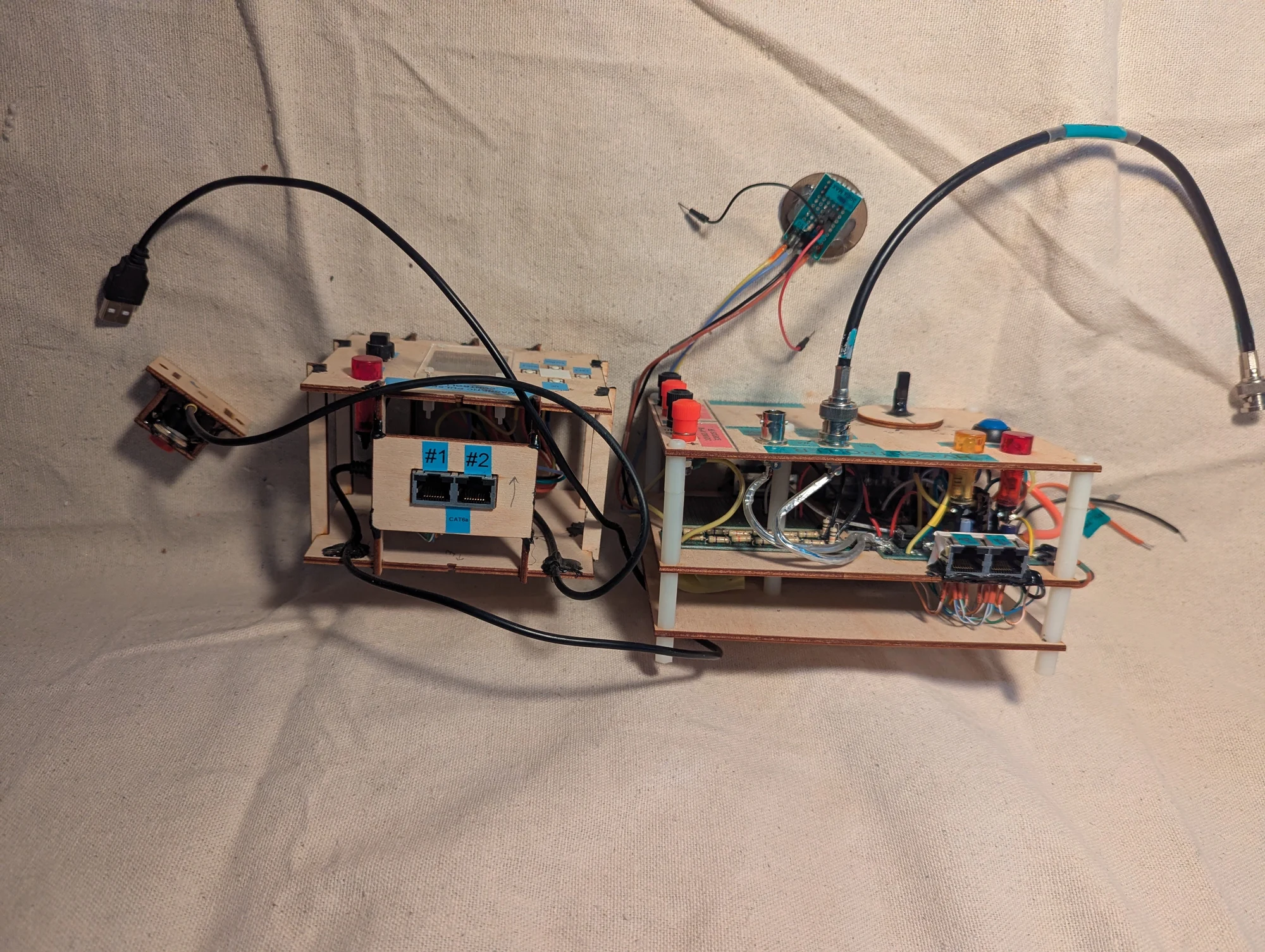
Another view of the magnetic-refrigeration controls, showing the user-interface box and the capacitor-charging controller. Network-style cables provided convenient control wiring between the assemblies; no Ethernet protocol was involved.
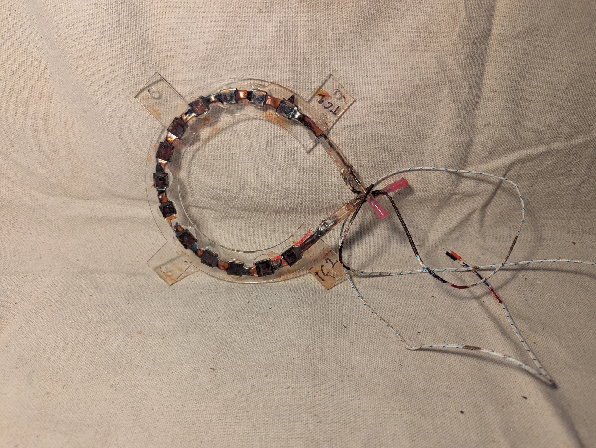
A crescent-shaped tube holding gadolinium pieces and ferrofluid, with thermocouples to track temperature and syringe tips for filling. I was investigating a cooling concept in which a rotating magnet would preferentially attract cooler ferrofluid and displace warmer fluid. Repeating that motion was intended to build a hot-to-cold temperature difference along the arc.
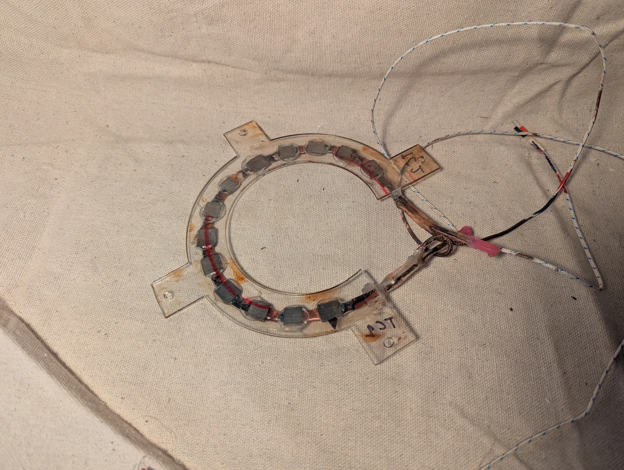
A second angle on the gadolinium-and-ferrofluid assembly. The concept explored whether temperature-dependent magnetic attraction could redistribute the fluid to create warmer and cooler ends of the arc. Thermocouples were attached to measure temperature changes.
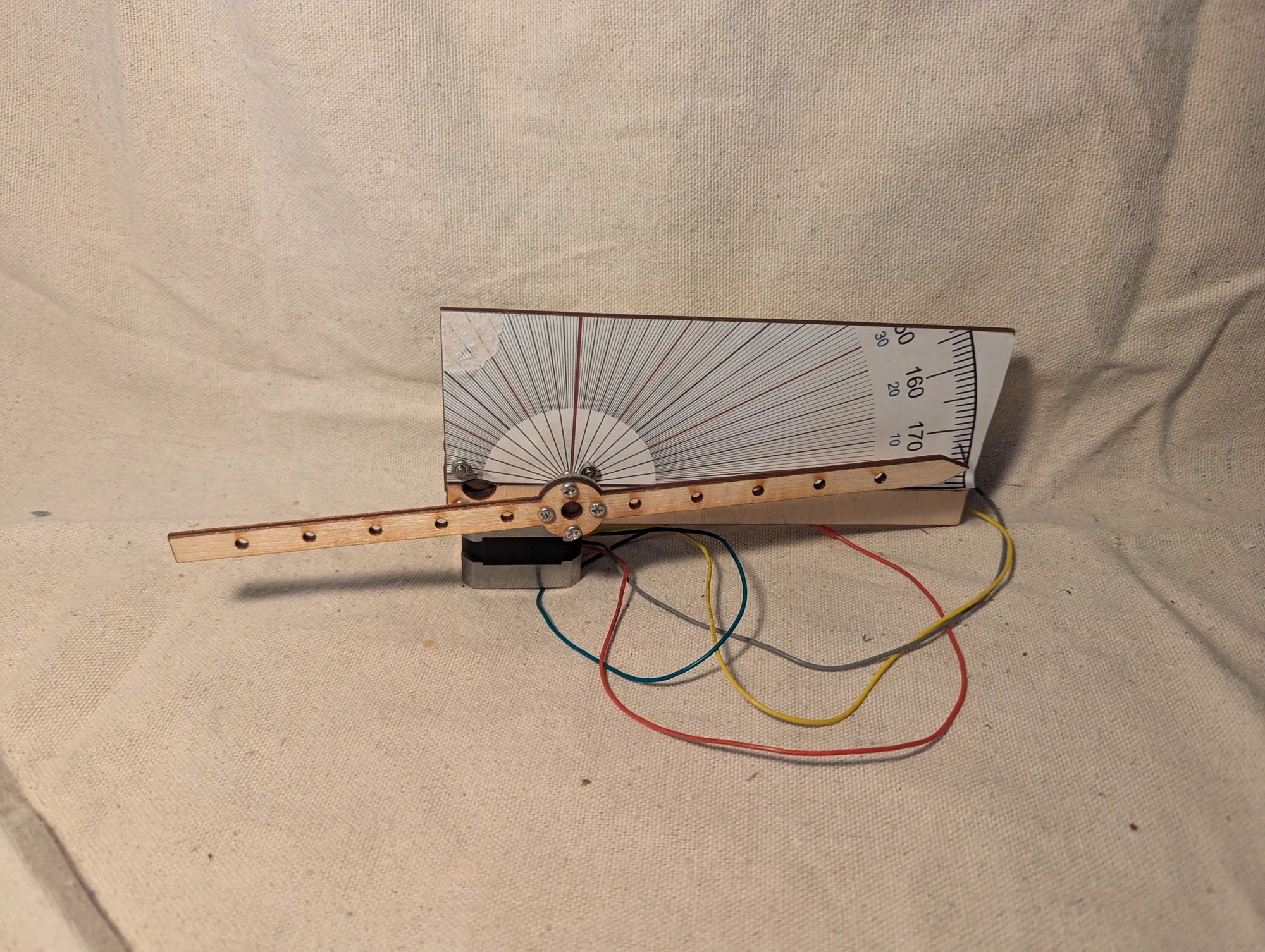
A contracted project investigating how precisely a stepper motor could move. I built this test fixture to measure the motion produced by individual motor steps. I no longer recall the exact gearing used in the setup.
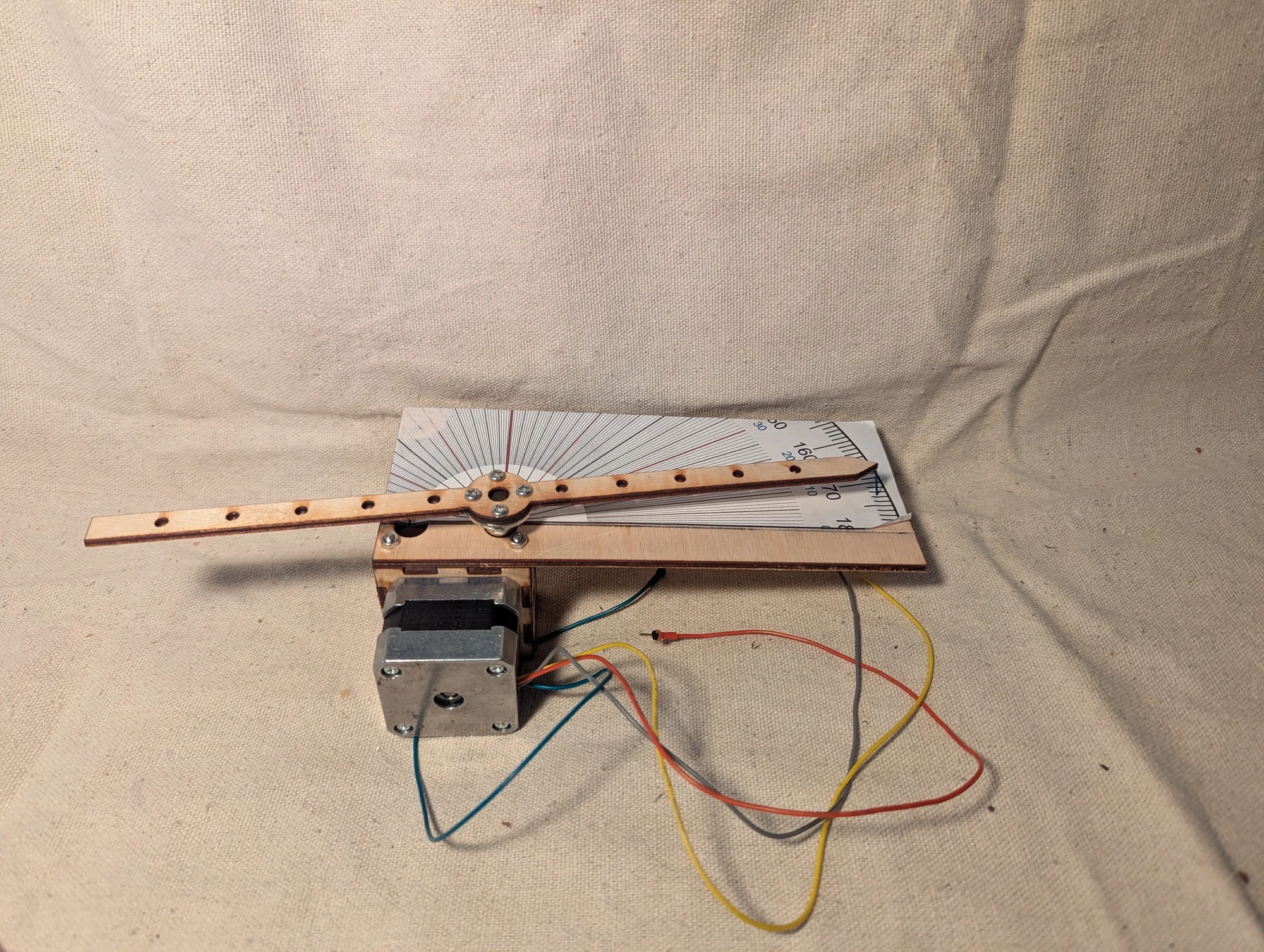
Another view of the stepper-motor test rig, showing the motor and measurement arrangement. This was part of contract work investigating movement per step.
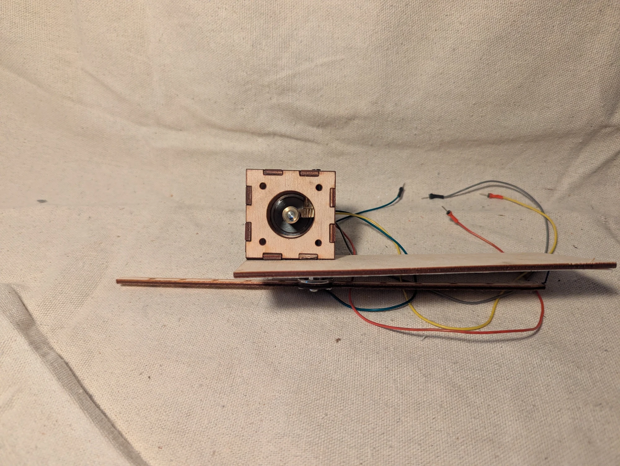
A further view of the fixture used to investigate stepper-motor motion, including its mechanical arrangement and wiring. The project focused on measuring individual steps.
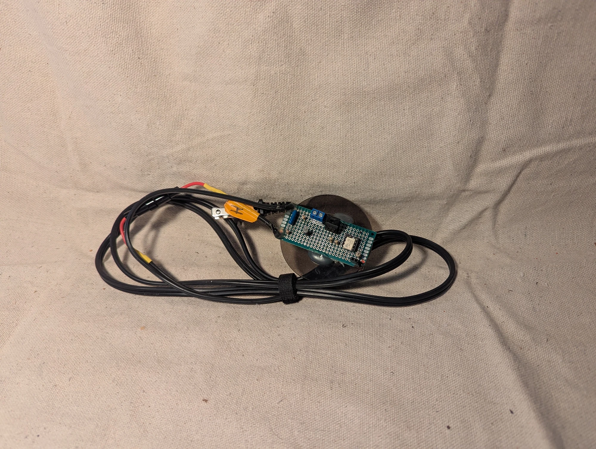
Another component of the capacitor-bank charging controller used in the magnetic-refrigeration project.
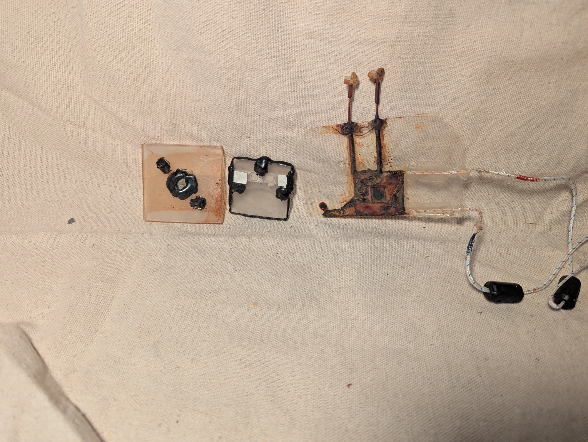
An experimental chamber made from two laminated sheets, with gadolinium inside. I used it to explore whether magnetic attraction could create a temperature gradient in ferrofluid.
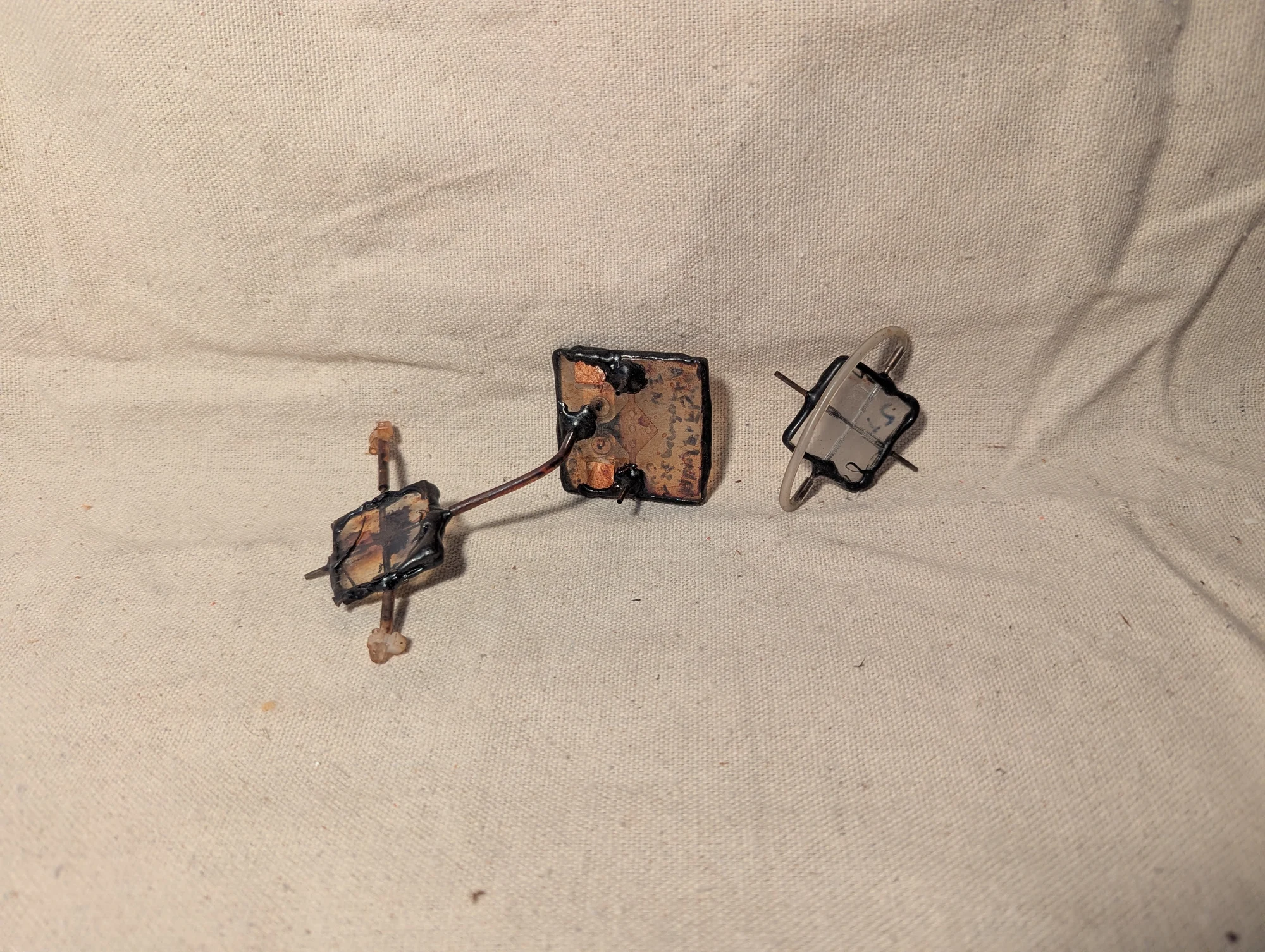
A small multi-port connector from my microfluidics experiments. It may have been intended to separate air from ferrofluid, with a mixed stream entering and liquid leaving through another port. I do not yet recall its exact function.
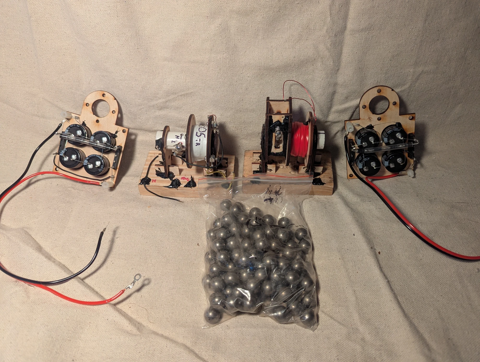
A bench layout from an early coilgun experiment, shown with its test hardware and steel balls. I was exploring mechanical triggering as part of the prototype.
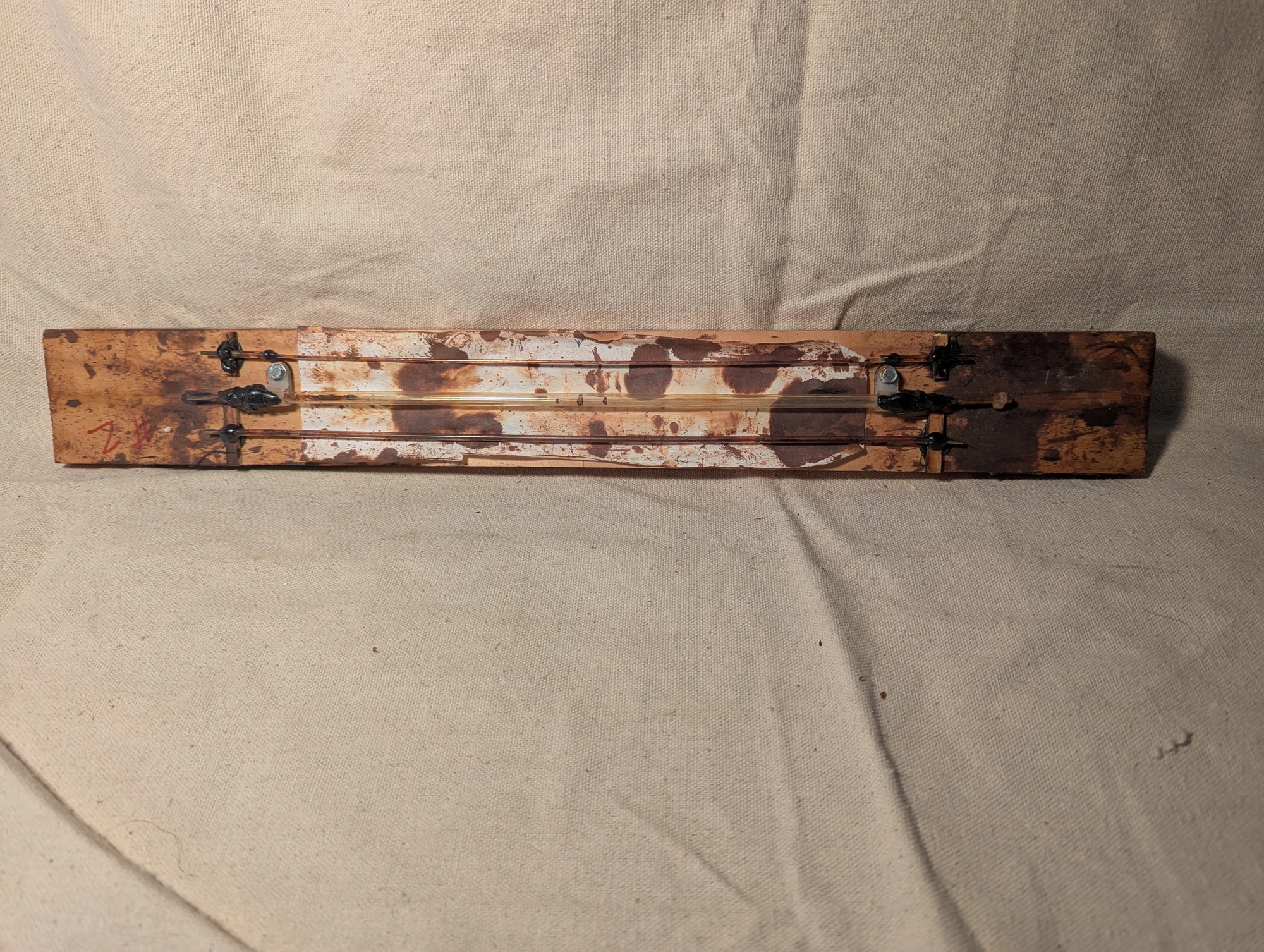
Manometers for ferrofluid experiments: instruments that indicate pressure through the height of a liquid column. I tried different tube diameters, including larger glass tubing and finer Tygon tubing, with blunt syringe-style fittings for connections.
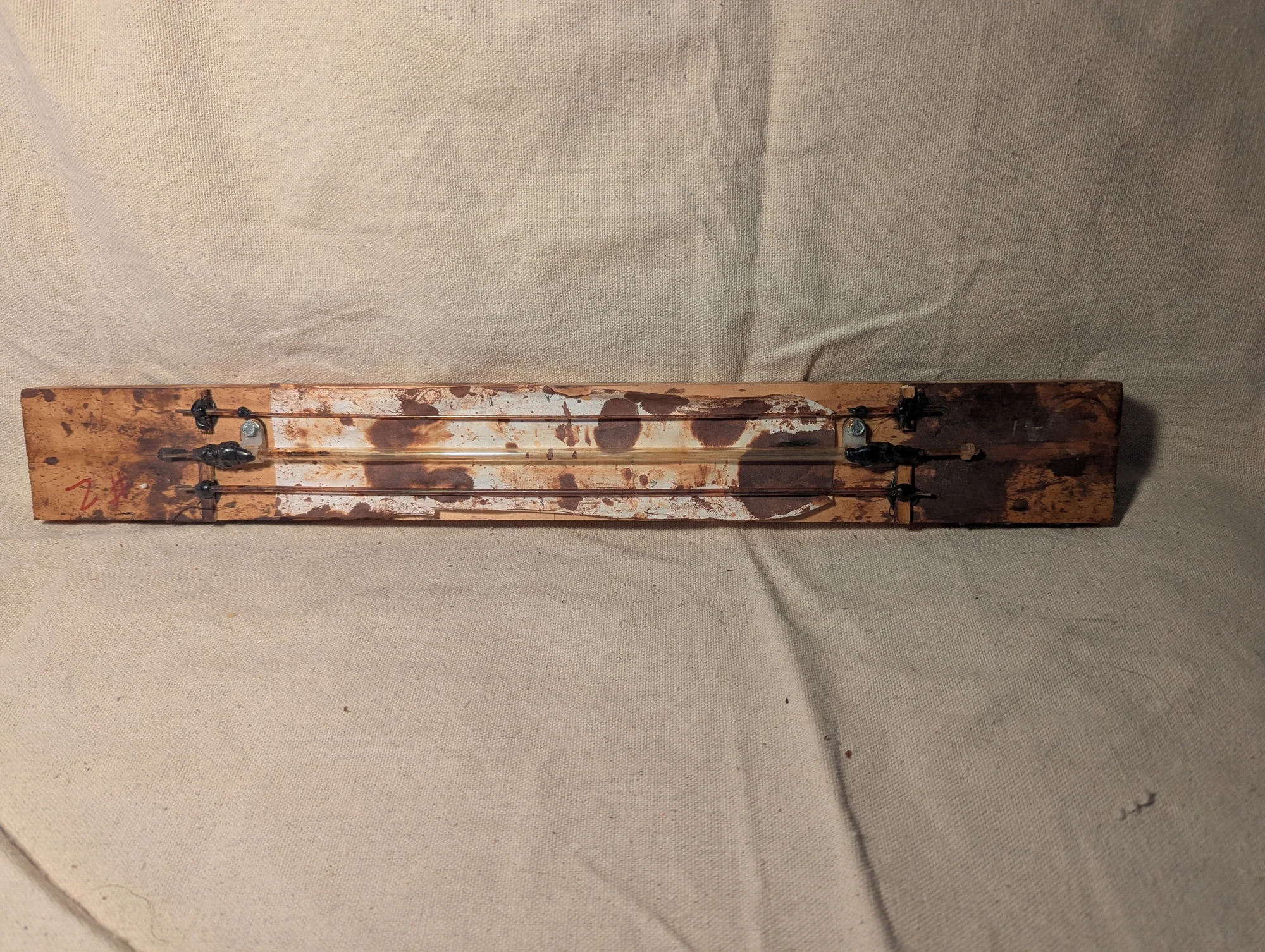
A second view of the manometer assemblies and their different tube sizes, built for pressure measurements during ferrofluid experiments.
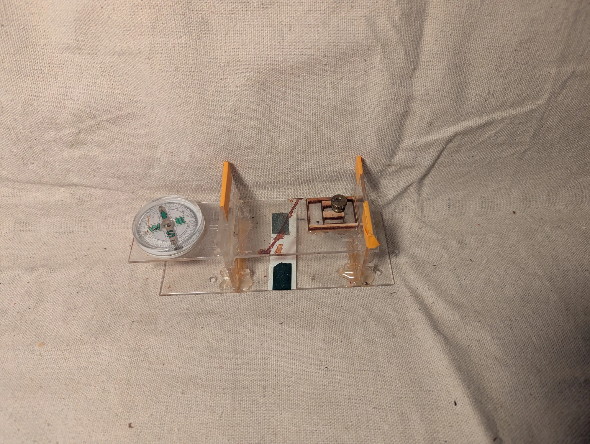
A simple magnetic-field indicator built around a compass and an adjustable magnet. I experimented with offsetting Earth's influence on the needle so nearby magnets would produce visible deflections. It worked as a rough analog indicator.
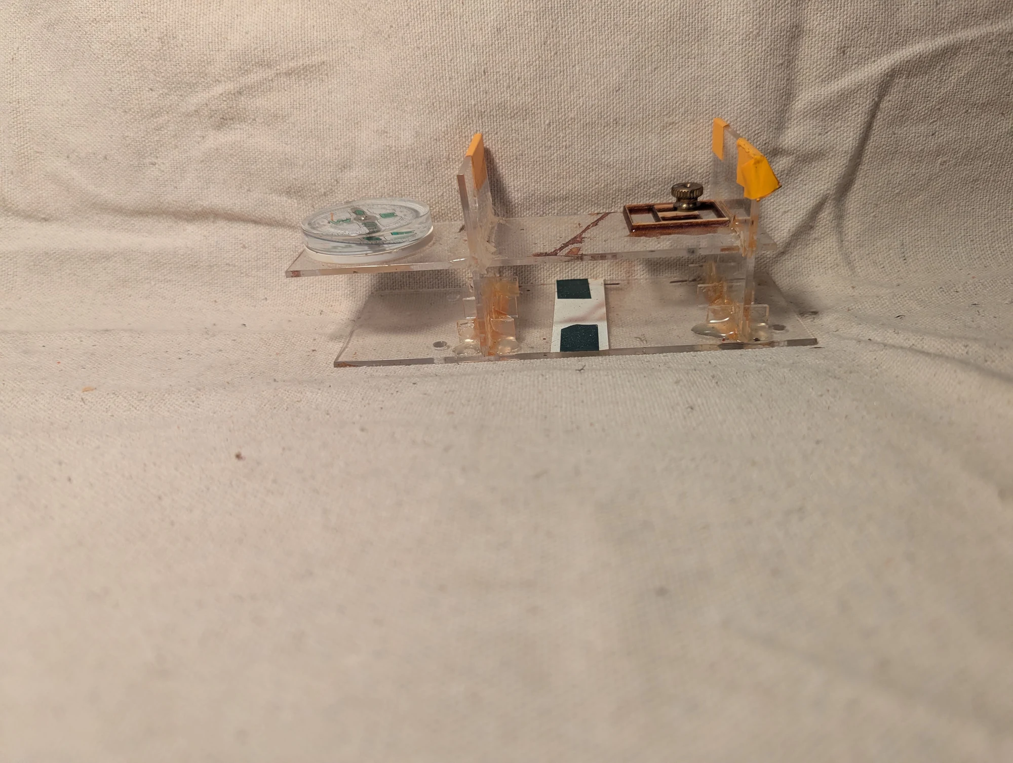
Another view of the compass-based field indicator, showing the arrangement used to change the magnet's position relative to the needle.
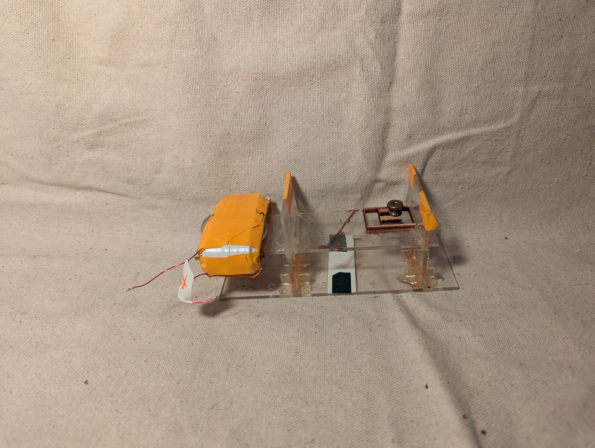
The compass setup with a large oval copper coil. I no longer recall the coil's exact role; it may have been used to offset Earth's magnetic field near the compass.
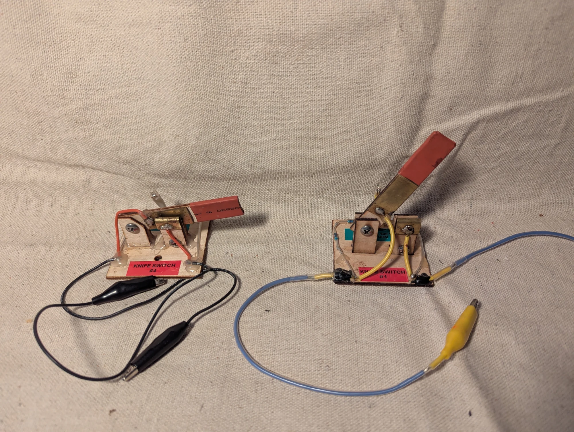
Two knife switches used in my early electrical and coilgun experiments, with brass contacts and small neon indicators. The indicators were intended to show whether a voltage difference was present across the contacts.
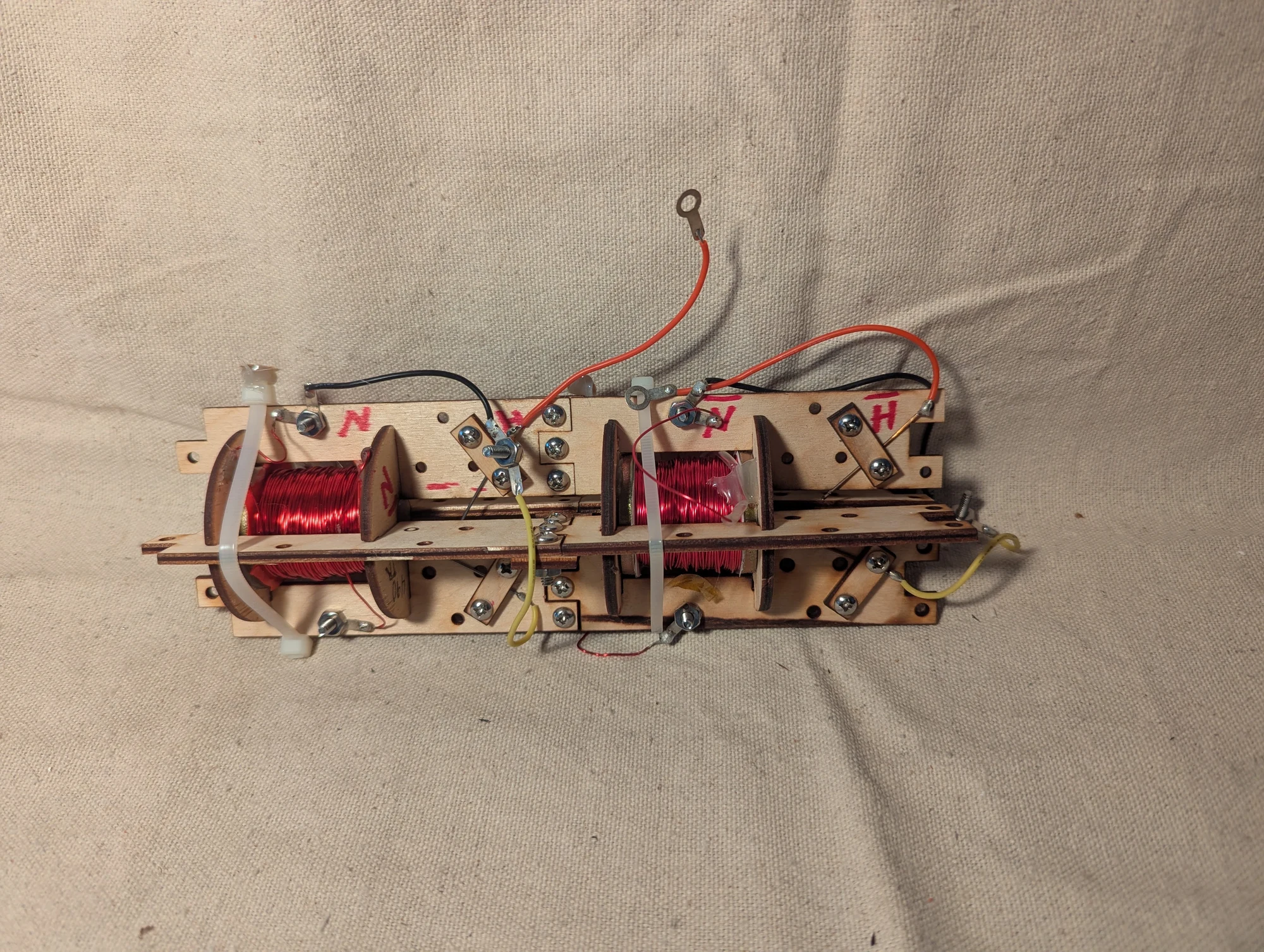
A later layout of the early coilgun experiment, with two experimental stages mounted together. This photograph records the development of the prototype's mechanical arrangement.
A photograph of a local storm-drain outlet and its surroundings.
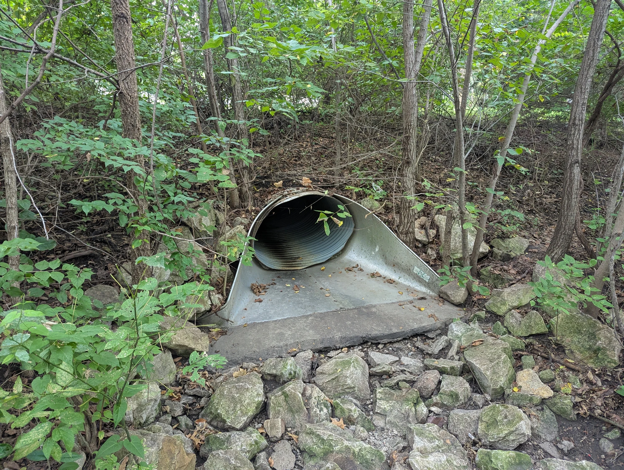
A second view of the storm-drain outlet.
Photos 365–419
Batch 06 · 54 photographs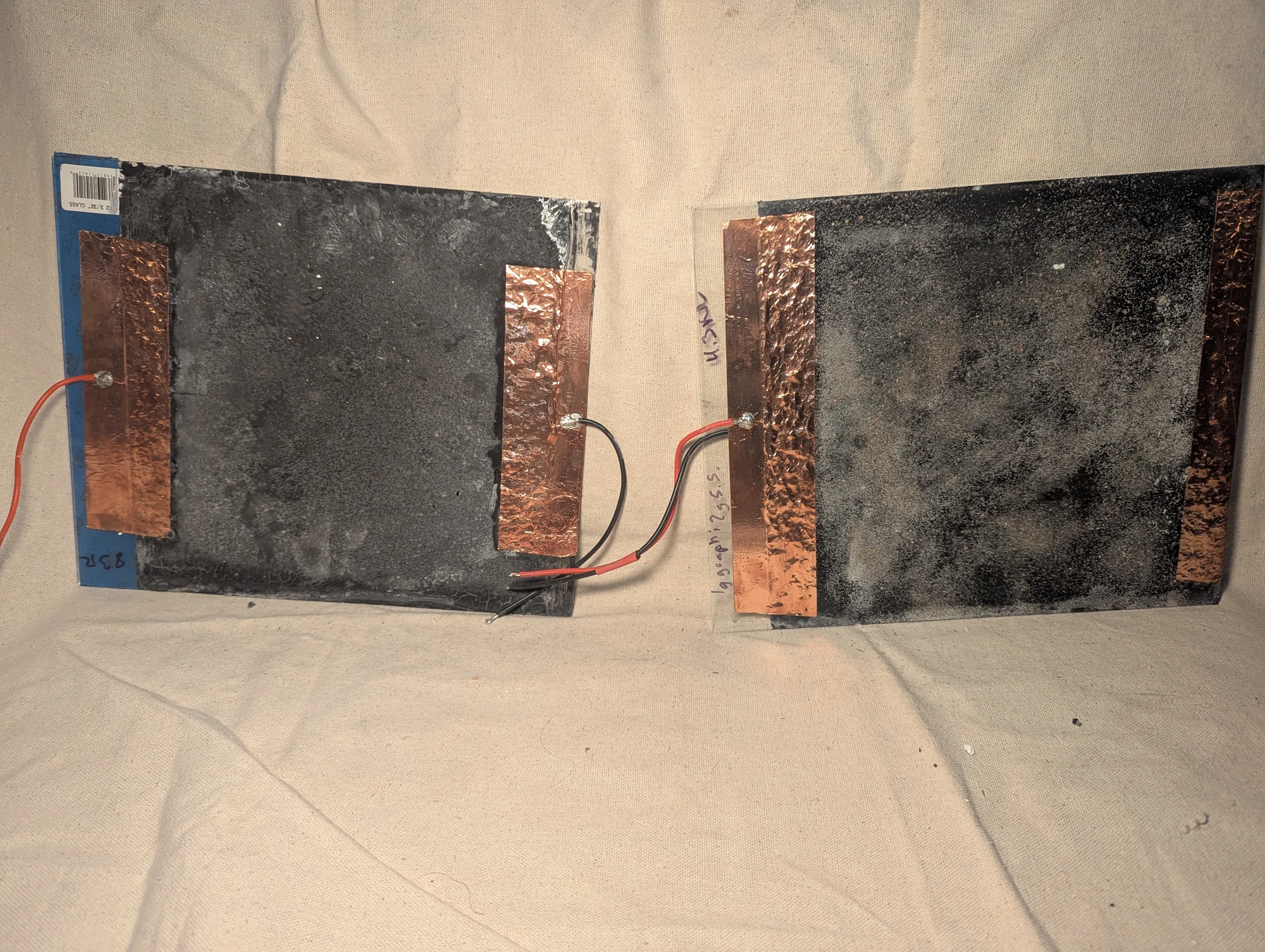
A paintable-heater experiment using flake graphite in a sodium-silicate binder on glass. Copper tape formed the electrical contacts and provided places to attach wires. A variable transformer, or Variac, let me adjust the power. I also added sand to roughen the surface, aiming to improve the heat it radiated.
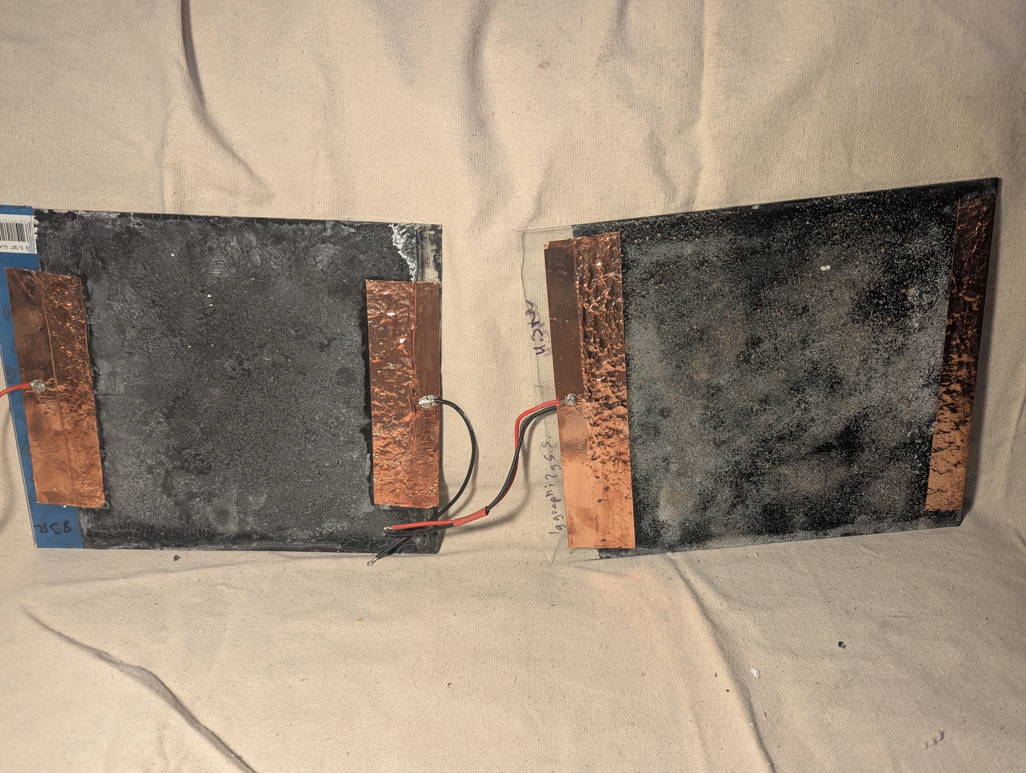
Graphite-coated glass heater samples with copper-tape contacts. These experiments explored using a conductive coating to heat a surface.
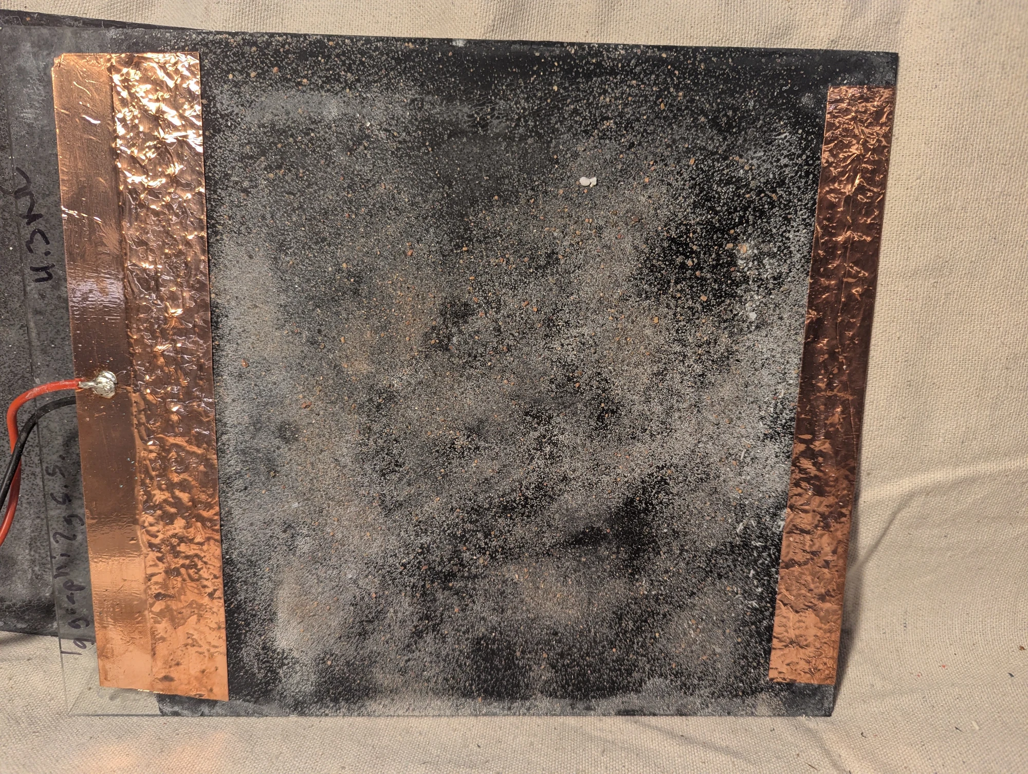
A closer view of a graphite-coated heater sample and its copper contacts. The textured surface came from experiments with roughening the coating.
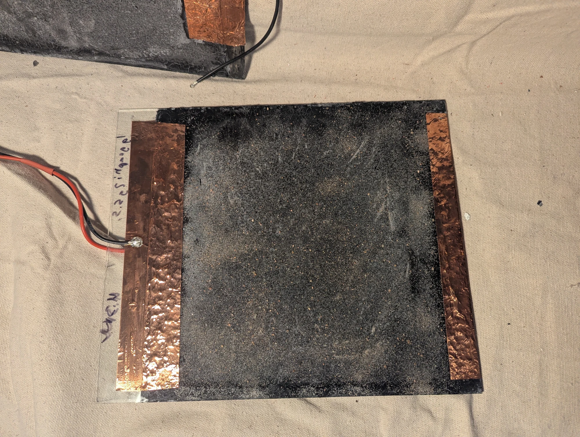
Another view of a paintable graphite heater on glass. The coating combined graphite pigment with a sodium-silicate binder, with copper tape providing the electrical connections.
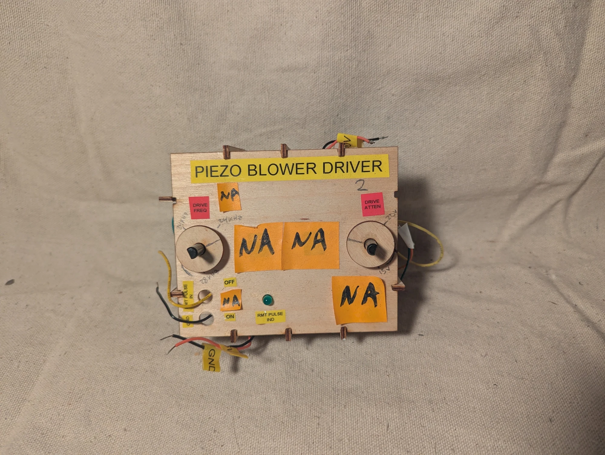
A driver I built for a piezoelectric blower, a small device that moves air through vibration. The controller supplied an adjustable electrical drive signal for airflow experiments involving small fluid volumes. Keeping water out of the blower was important.
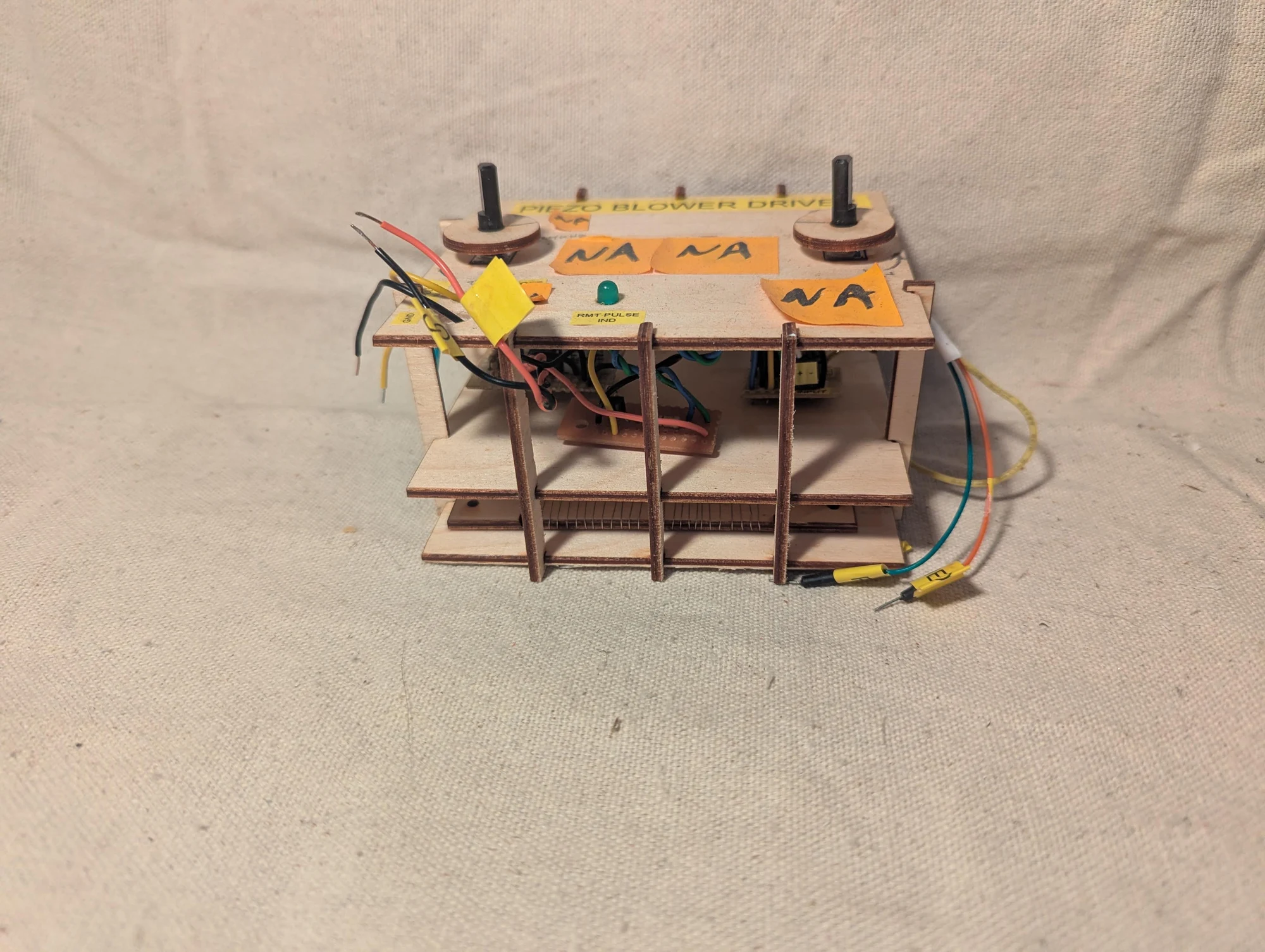
Another view of the piezoelectric blower driver, showing its controls and supporting frame.
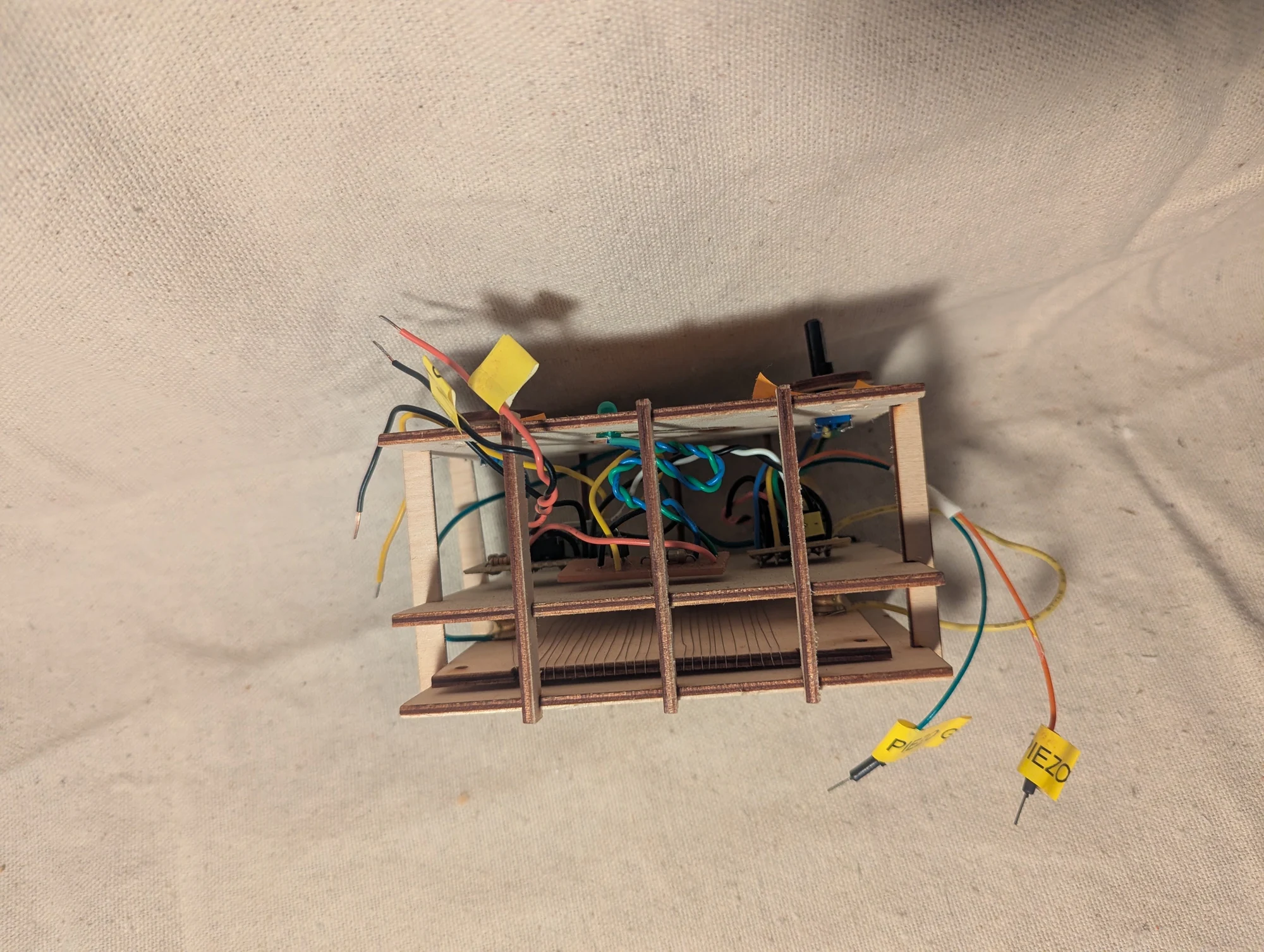
A different angle on the piezoelectric blower driver and its wiring.
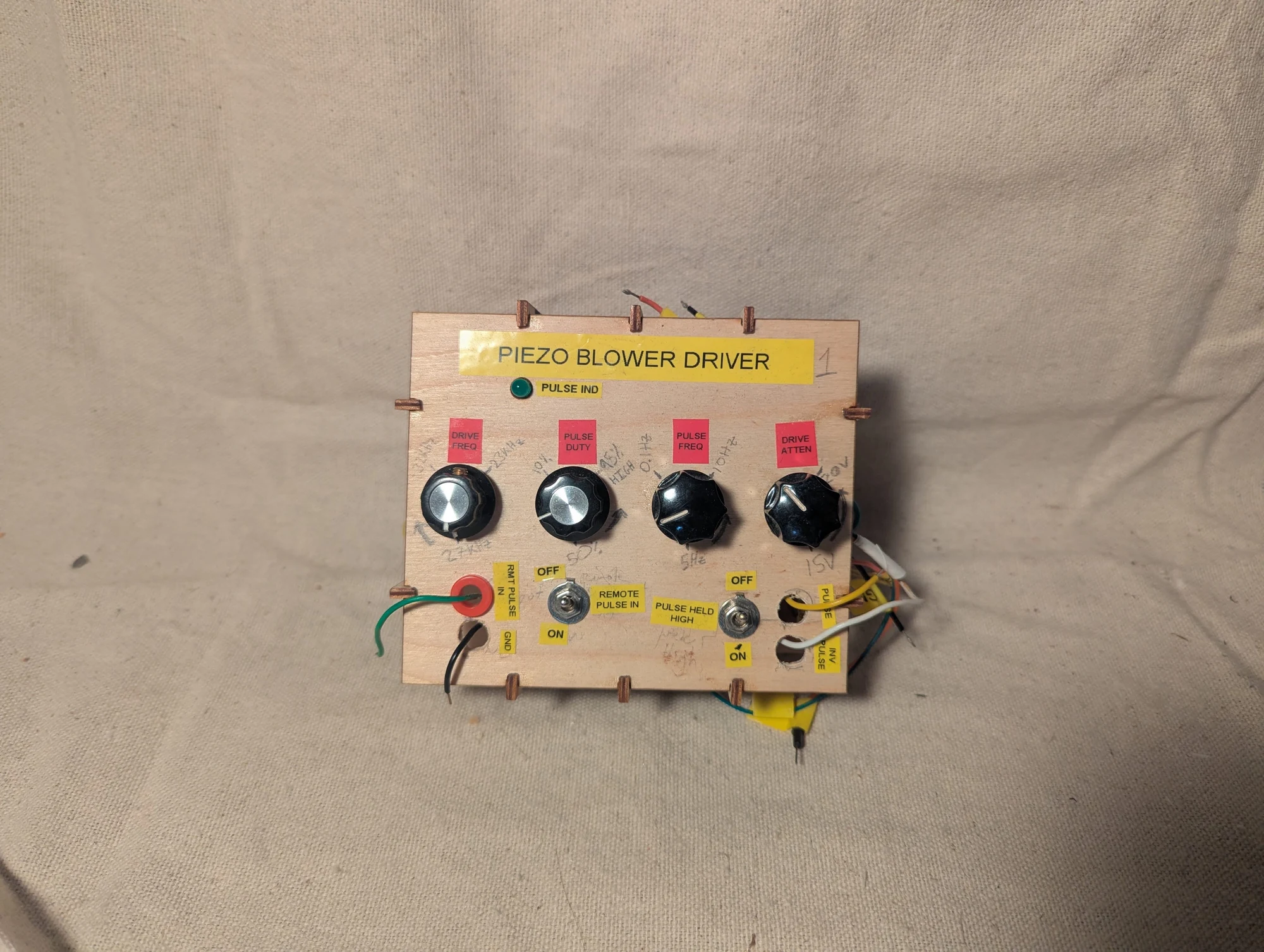
A second piezoelectric blower driver, built so I could run multiple blowers. I believe the paired blowers were used to push air from opposite sides of a fluid system, moving ferrofluid back and forth during the magnetic-refrigeration experiments.
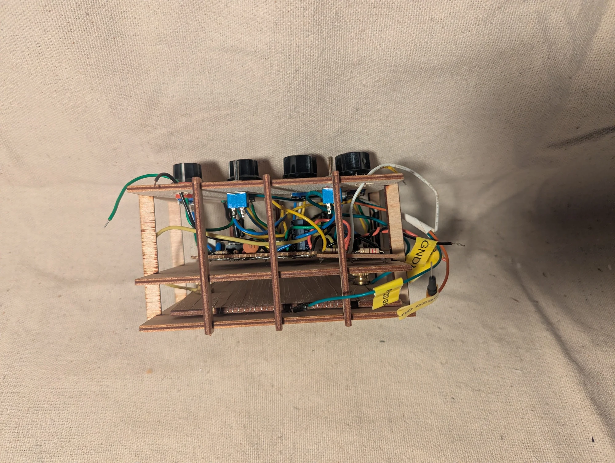
Another angle on the second blower-driver assembly used in the paired-blower experiments.
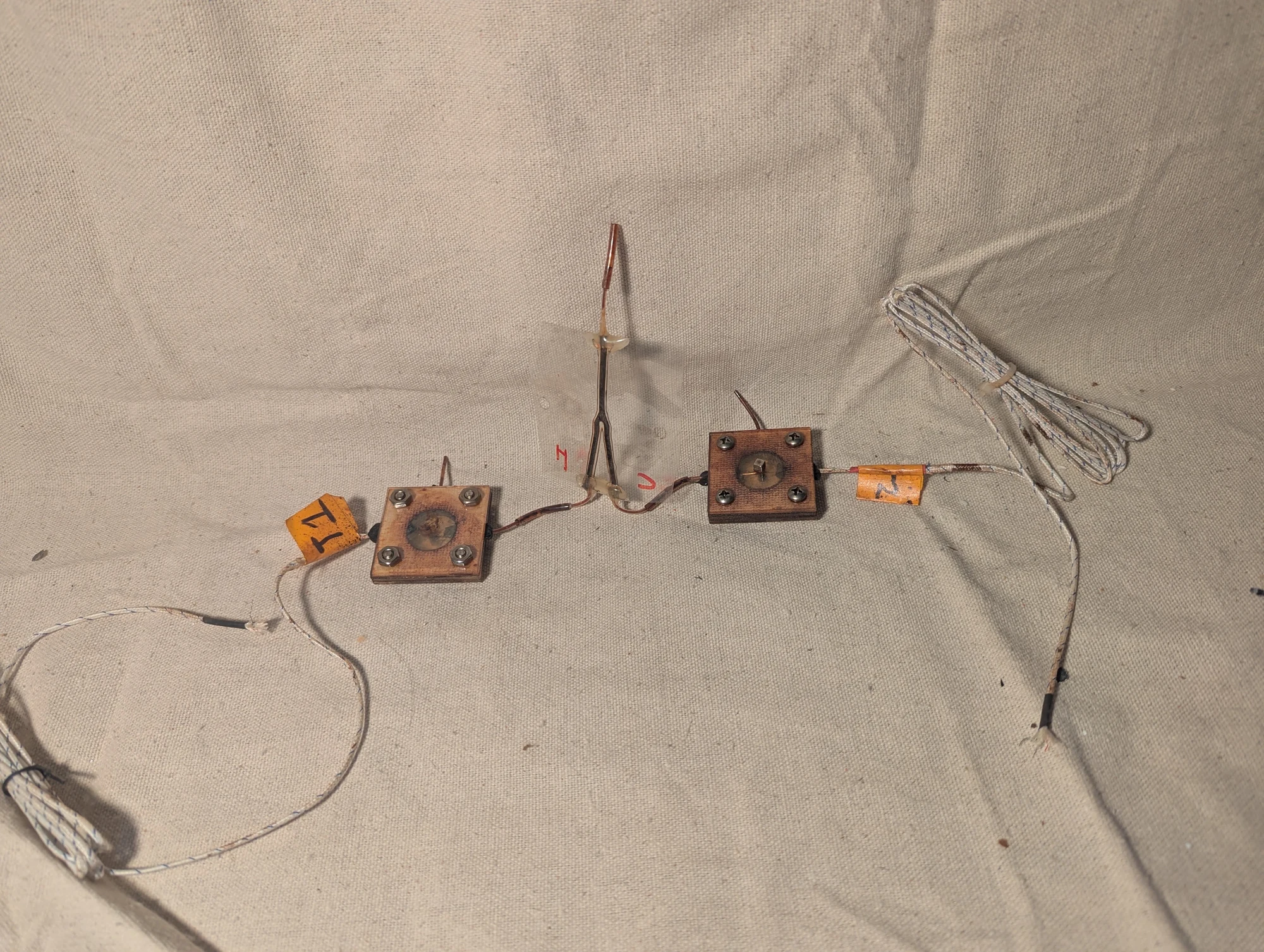
An experiment to test whether warmer and cooler ferrofluid would separate near a magnet. I introduced a mixture of the two into the tube, then positioned one thermocouple near the magnet and another a few millimeters farther away. I recorded and graphed the temperatures to look for a difference between the regions.
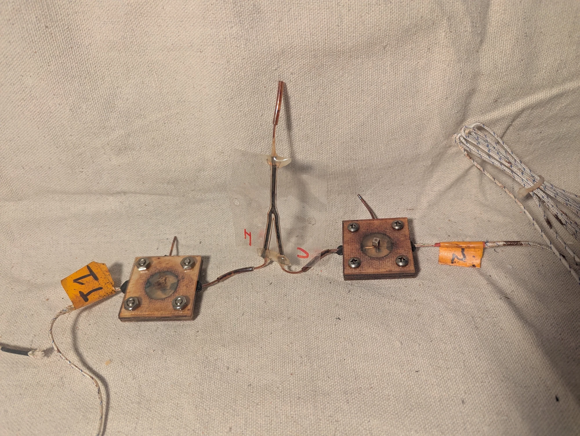
Another view of the ferrofluid experiment in Photo 374. Temperature probes near the magnet and just outside that region let me compare where cooler and warmer fluid might collect. A data logger recorded the readings for plotting.
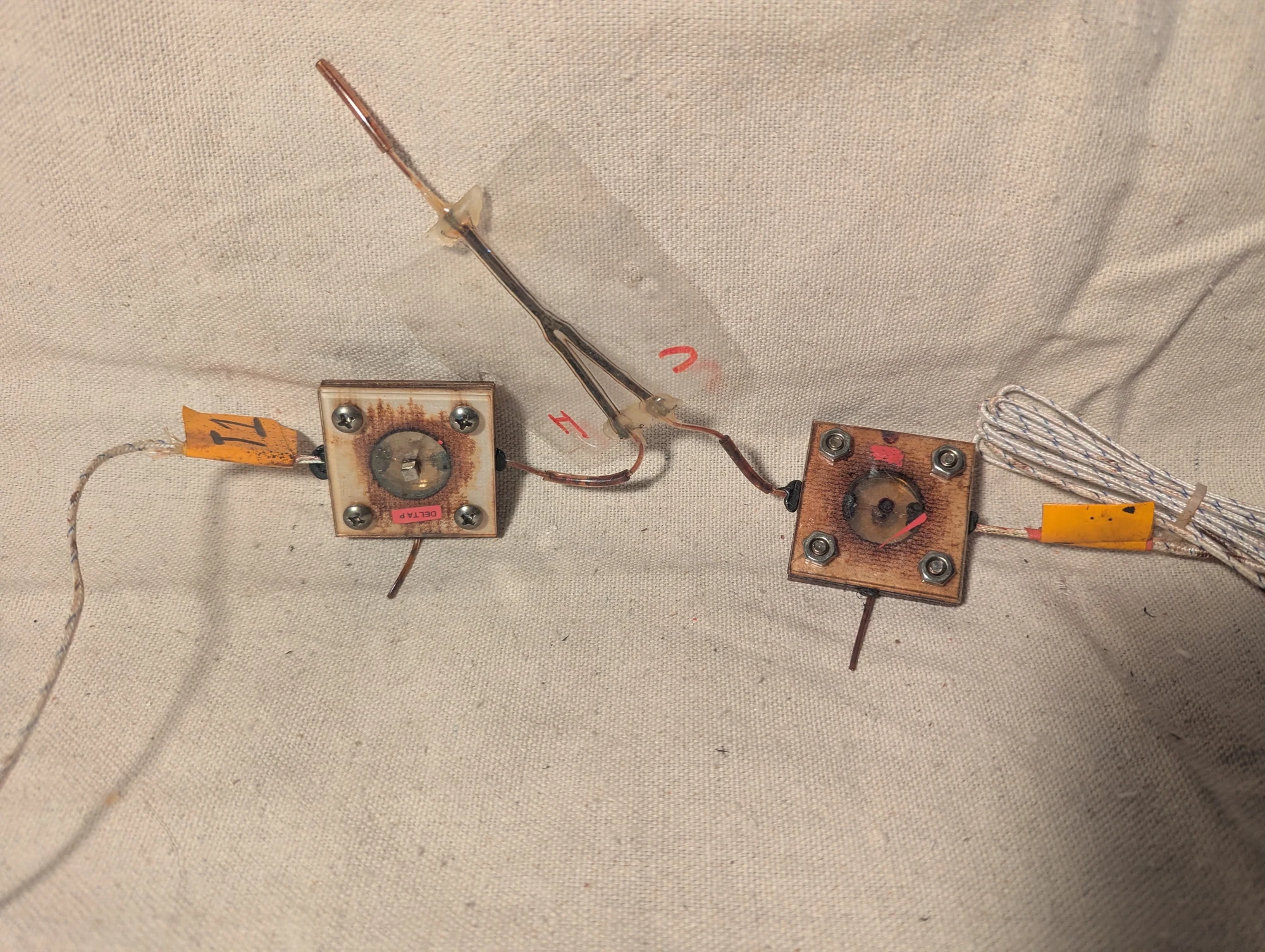
A closer view of the setup used to investigate temperature differences in ferrofluid near a magnet. The experiment compared two nearby locations after introducing warmer and cooler fluid into the chamber.
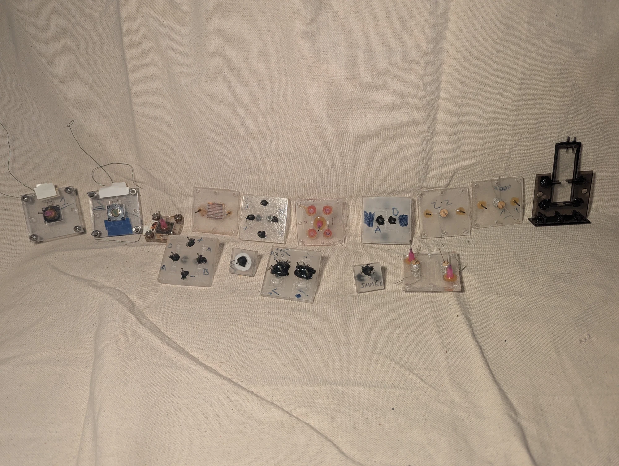
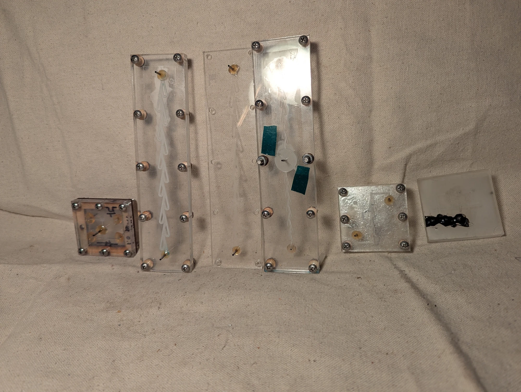
These homemade microfluidic chips guide small amounts of liquid through channels inside acrylic. I laser-cut or engraved the patterns, then sanded, cleaned, and bonded the stacked layers using heat and pressure. The collection includes one-way flow elements, pressure-controlled valves, heat exchangers, and winding channels for a fluorescent-dye display experiment.
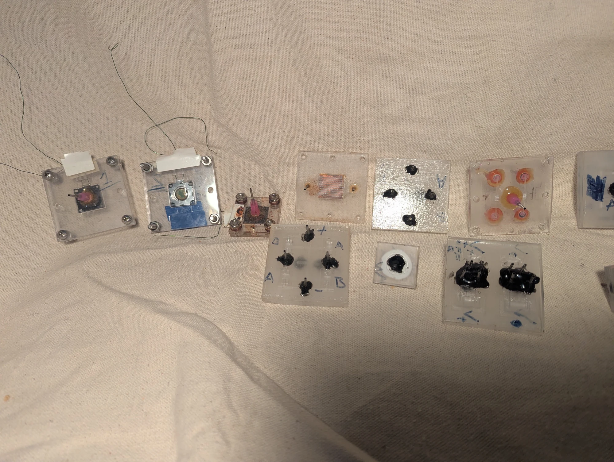
Another view of the microfluidic collection. Patterns engraved into acrylic became enclosed fluid paths when the layers were bonded together with heat and pressure. I used these prototypes to try different ways of routing ferrofluid and other liquids.
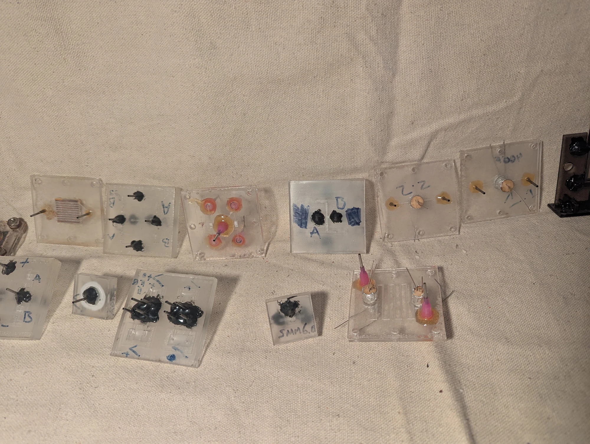
A closer view of the acrylic prototypes. Across the collection, I experimented with silicone flaps for one-way flow, flexible membranes for pressure-controlled valves, and optical sensing. These were separate trials of small fluid-handling components.
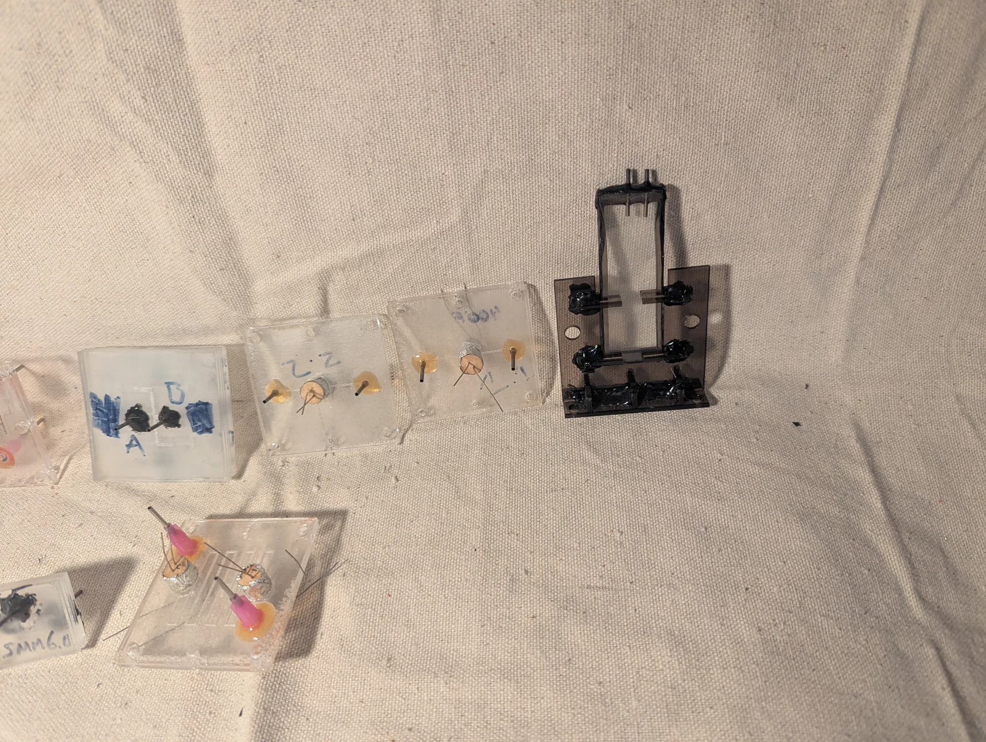
Part of the acrylic microfluidics collection. The broader project combined small fluid channels with pumps, sensors, and heat-transfer surfaces. Piezoelectric blowers supplied air pressure for some experiments, while light sensors helped detect moving fluid.
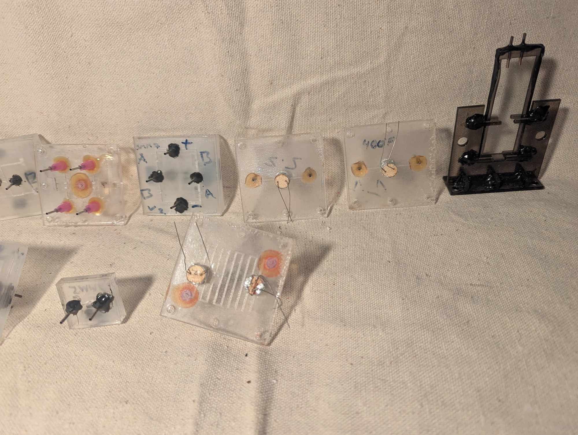
A further view of the stacked-acrylic prototypes and their supporting hardware. I used the same fabrication approach to explore several functions, including controlling flow and moving a small segment of fluorescent dye through a channel.
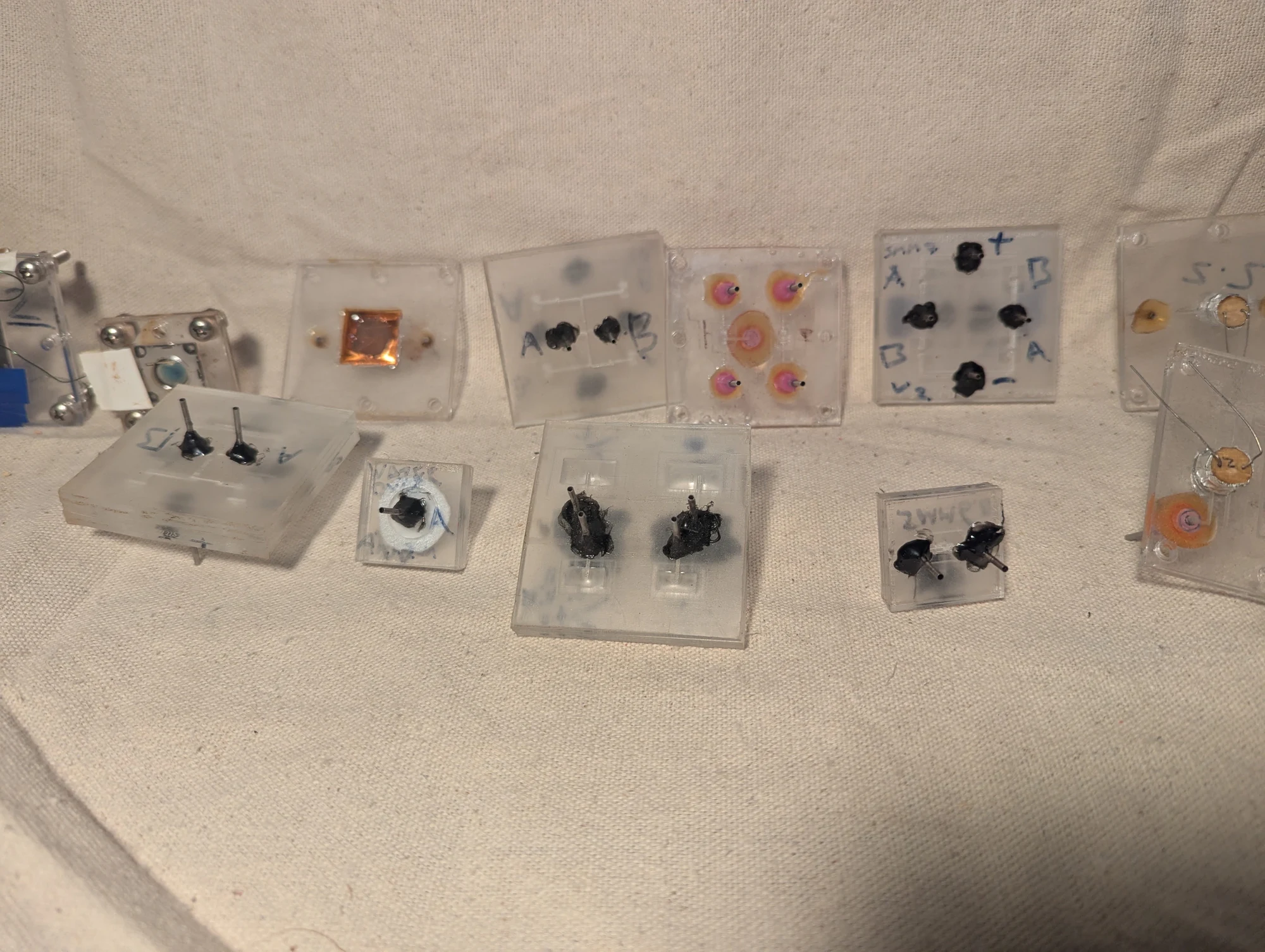
A selection of acrylic microfluidic prototypes with different internal layouts. Laser engraving let me try fine channel patterns before bonding the layers into enclosed devices. The designs supported experiments in fluid routing, valves, heat exchange, and optical detection.
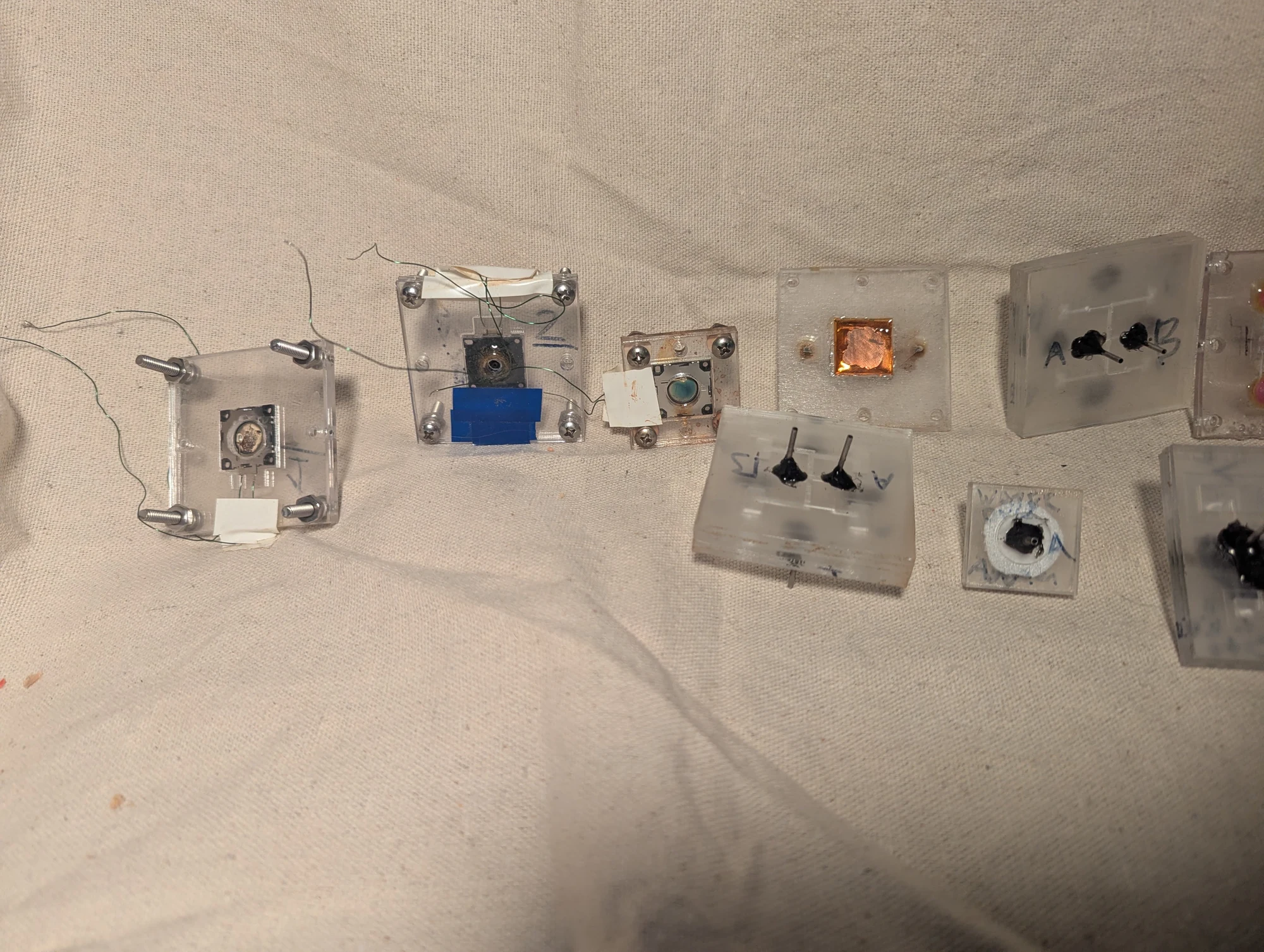
Another part of the microfluidic collection. Some designs incorporated copper surfaces so liquid could pass directly over a heat-transfer plate; others explored valves and sensing. These prototypes helped me investigate individual components before combining them into larger experiments.
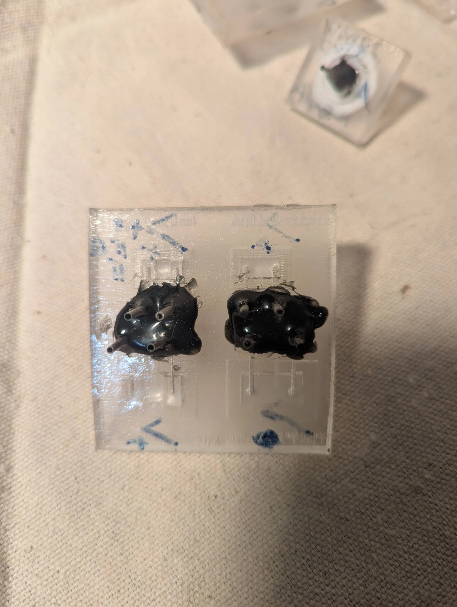
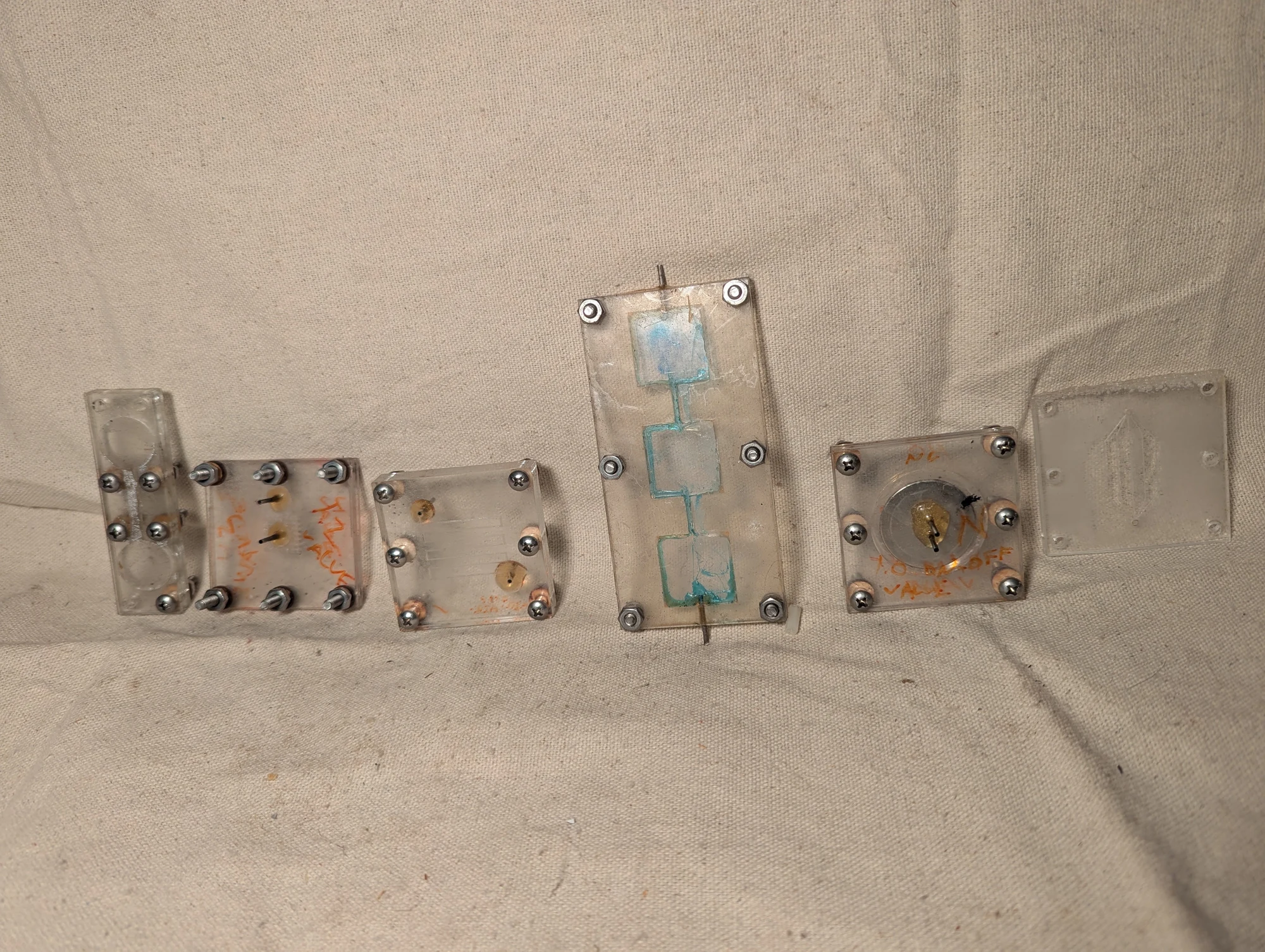
These miniature switches control liquid flow using a flexible silicone membrane. Each has an inlet, an outlet, and a separate pressure connection. Applying pressure expands the membrane into the flow path, blocking the connection between the other two ports.
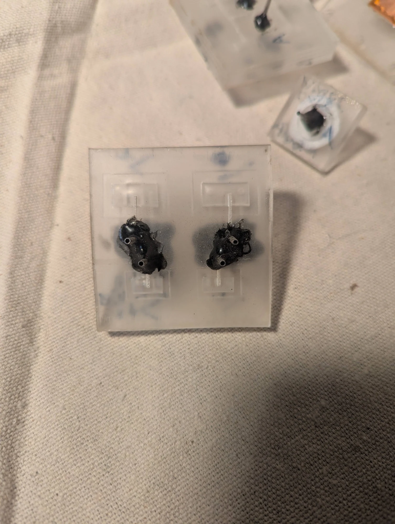
Another view of the microfluidic switches. A separate pressure signal moves a silicone membrane to close the liquid path, providing a way to control flow without placing an electrical switch in the fluid.
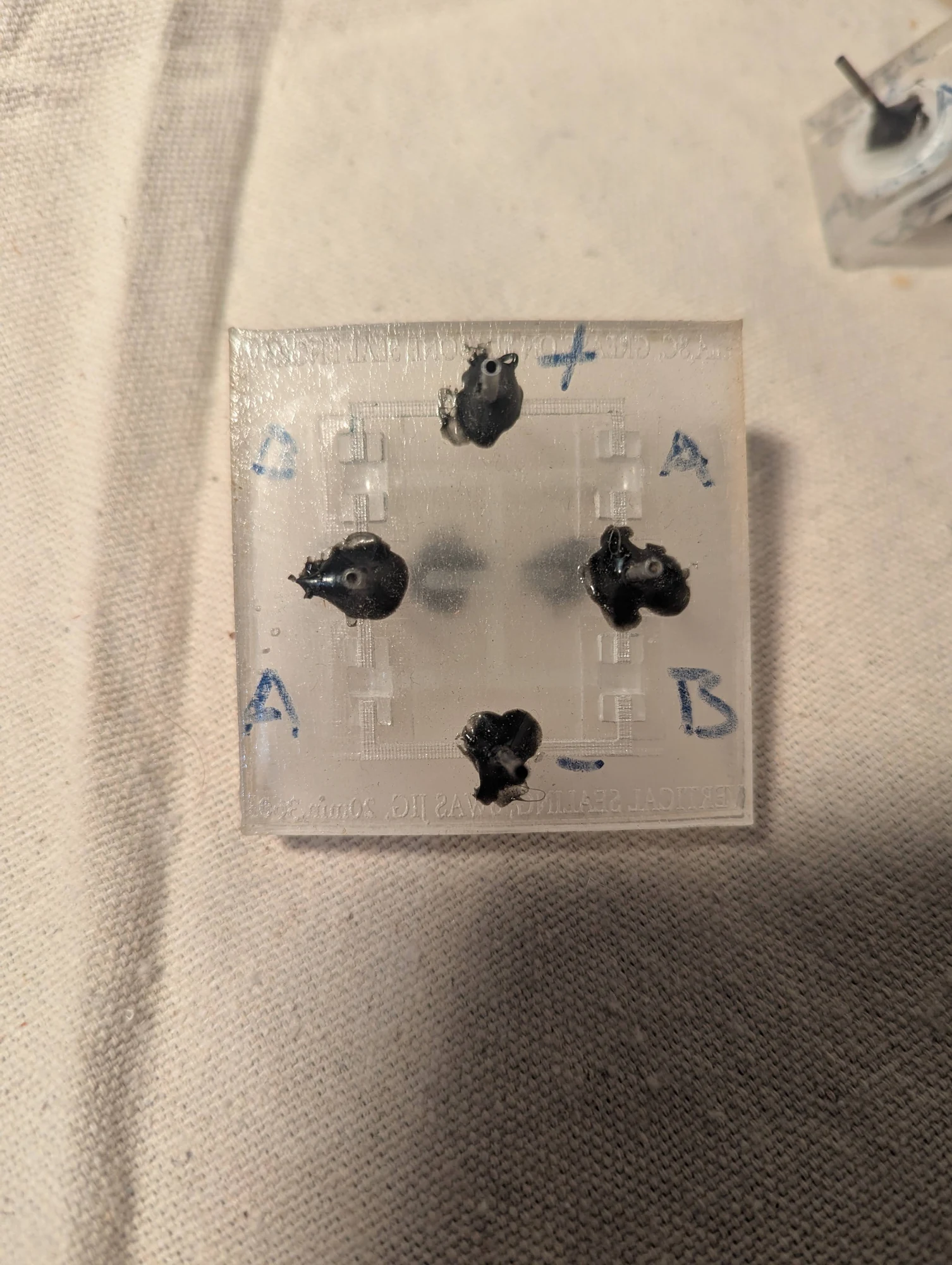
Four pressure-controlled valves combined into a fluidic H-bridge. Borrowing the layout of an electronic switching circuit, this prototype explored how several small valves could work together to select different paths for liquid flow.
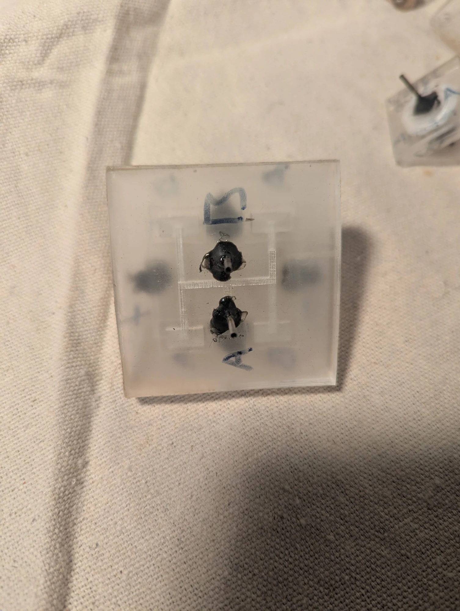
An alternate view of the four-valve assembly. The H-bridge name refers to the arrangement of interconnected flow paths; the switching elements here control fluid rather than electrical current.
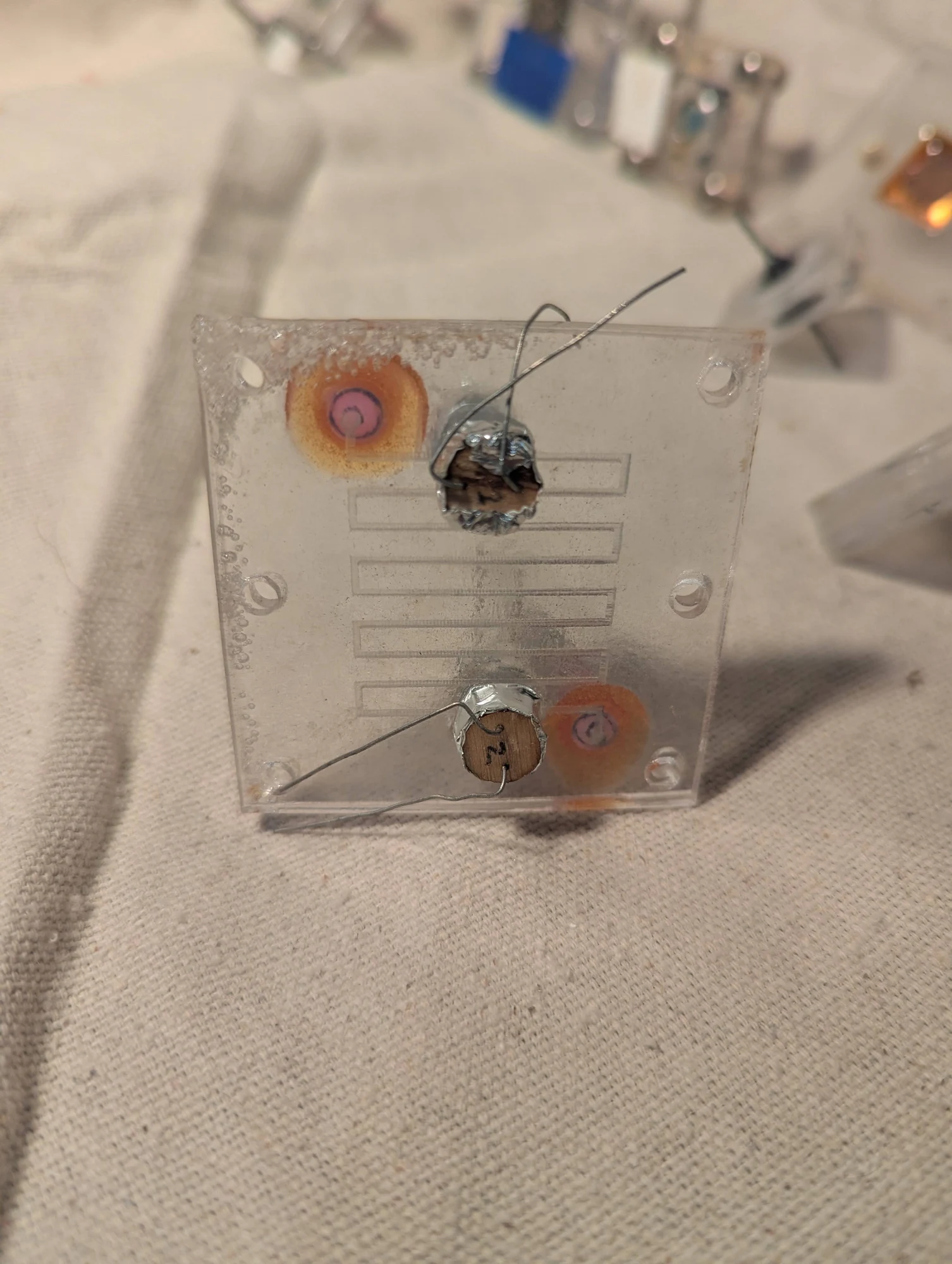
A serpentine channel for an experimental display. The idea was to move a small segment of fluorescent dye quickly through the channel and flash ultraviolet light at selected moments, lighting it at different positions. An LED and photoresistor detected the dye near the exit so a piezoelectric blower could apply pressure to stop it leaving the channel.
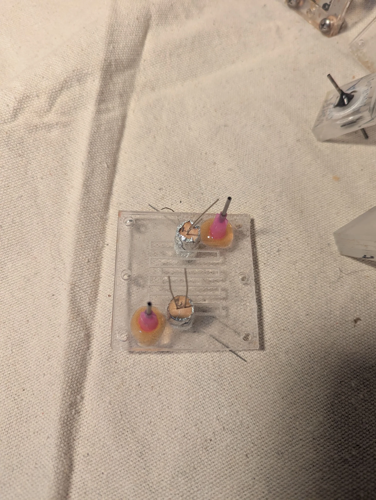
Another angle of the serpentine channel and optical detector. I was exploring a display in which the position of a moving dye segment and the timing of ultraviolet flashes would determine where light appeared.
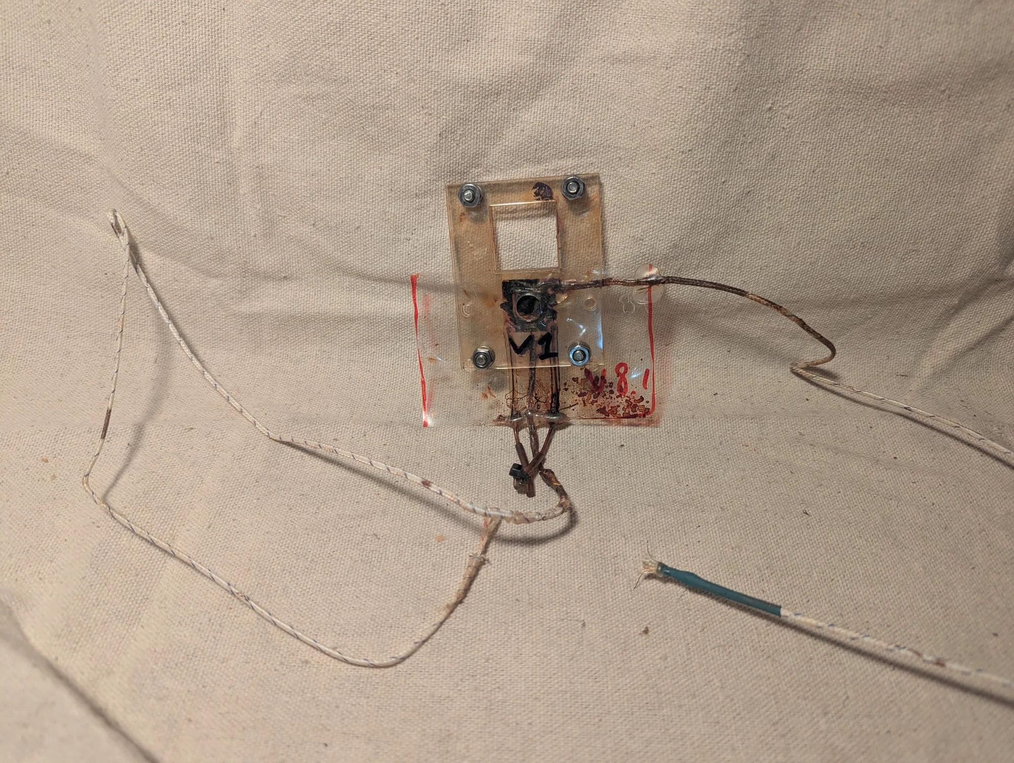
A small gadolinium square held in a pocket of ferrofluid, with thermocouples attached. I used this arrangement to look for temperature changes when the sample was exposed to a magnetic field, as part of my experiments with magnetic refrigeration.
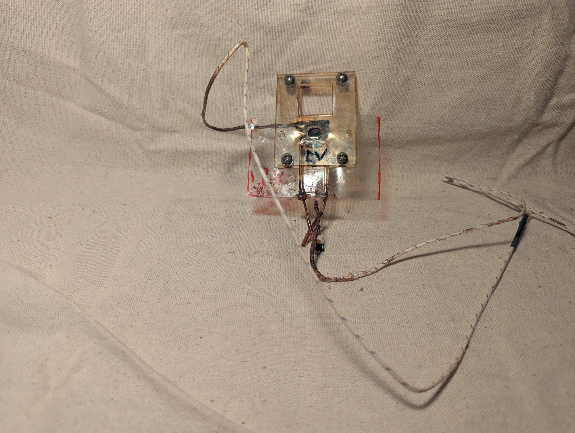
An alternate view of the gadolinium-and-ferrofluid test chamber. The attached temperature probes were intended to help measure the sample’s response to an applied magnetic field.
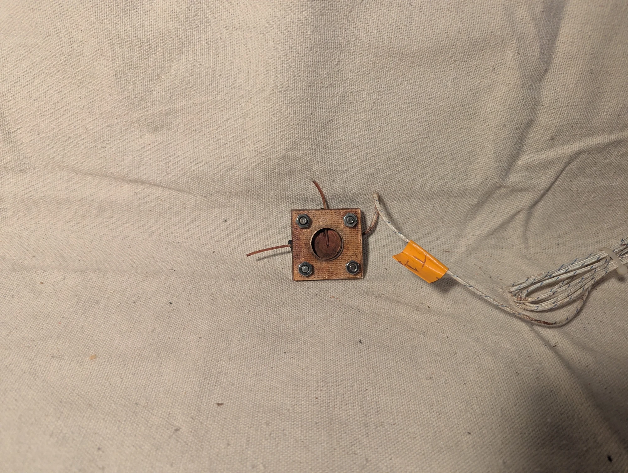
A microfluidic test chamber from this series of experiments. I believe it was used to investigate temperature changes, although I no longer recall the precise test configuration.
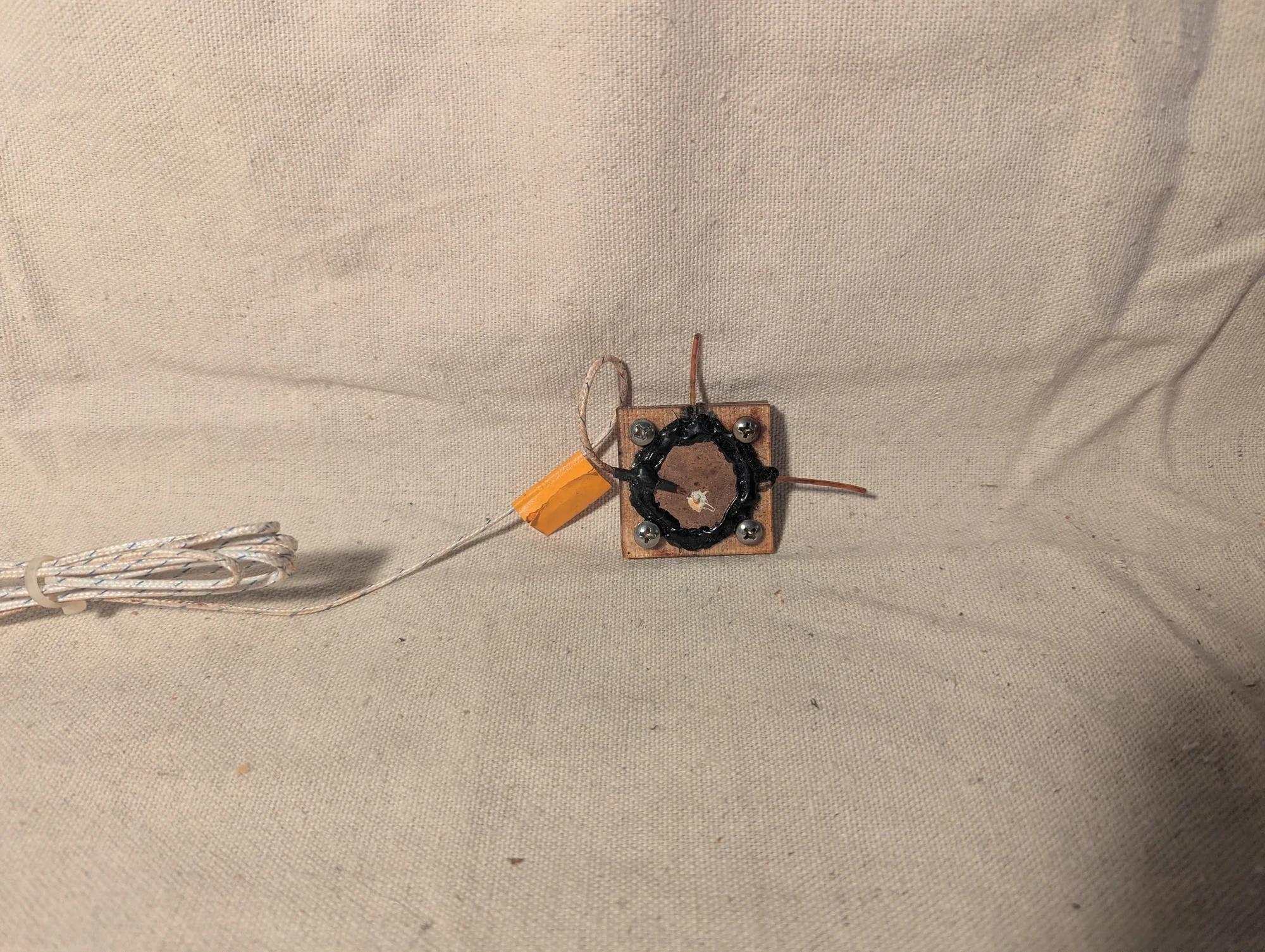
Another angle of the small fluid chamber and its connections. Its exact purpose is uncertain, but it appears to belong to the temperature-measurement experiments.
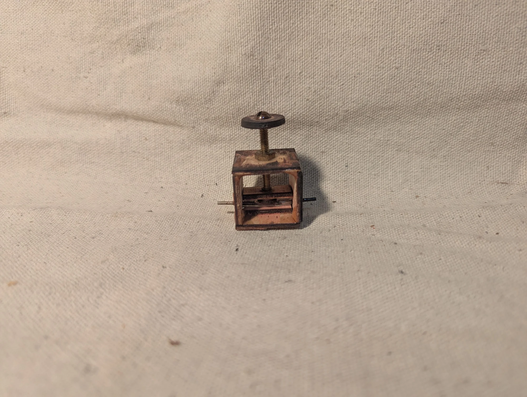
A simple mechanical valve for small fluid lines. Turning the screw presses against flexible Tygon tubing, narrowing or closing the passage to control flow.
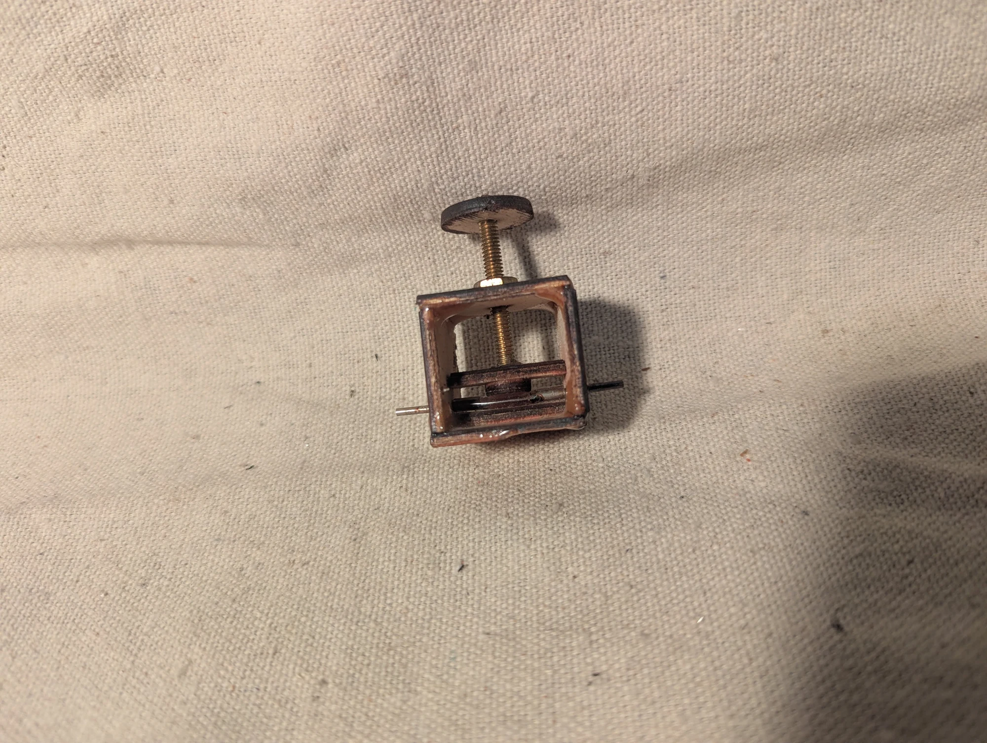
An alternate view of the pinch valve. The screw adjusts how firmly the flexible tube is compressed, providing a manual way to restrict or stop the liquid passing through it.
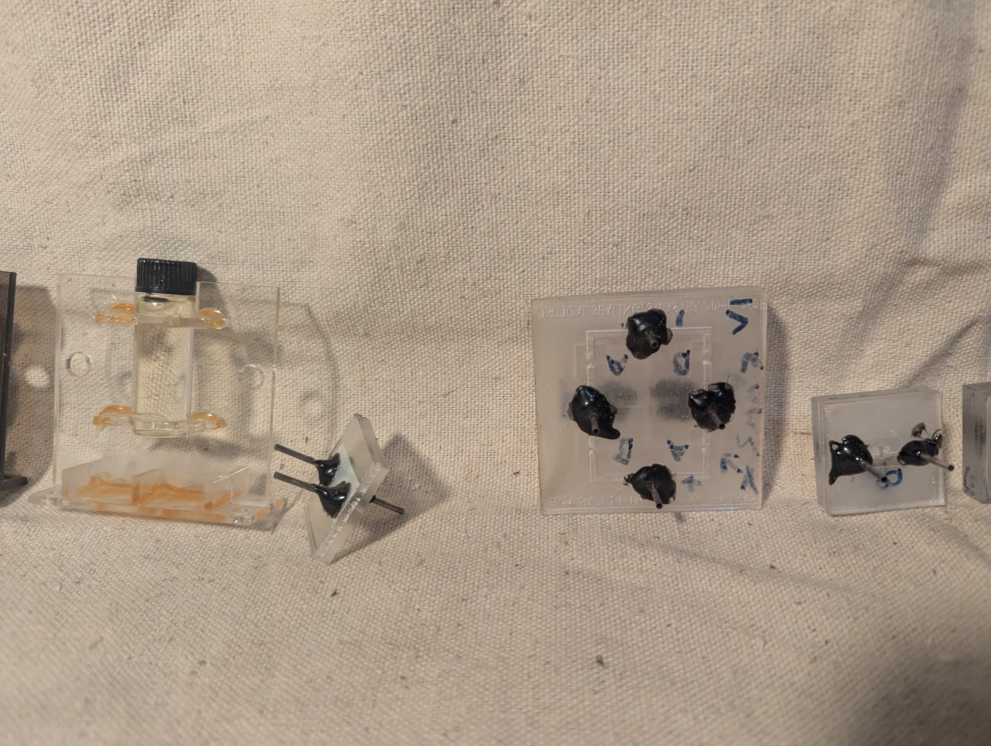
A collection of pressure-controlled valves and one-way flow elements. I thought of these as fluidic versions of MOSFETs and diodes: a control signal could close a flow path, while a flexible flap could allow flow in one direction and resist it in the other.
Another view of the experimental valves and one-way elements. The comparison with electronic components helped me think about combining simple fluid-control functions into more complex devices.
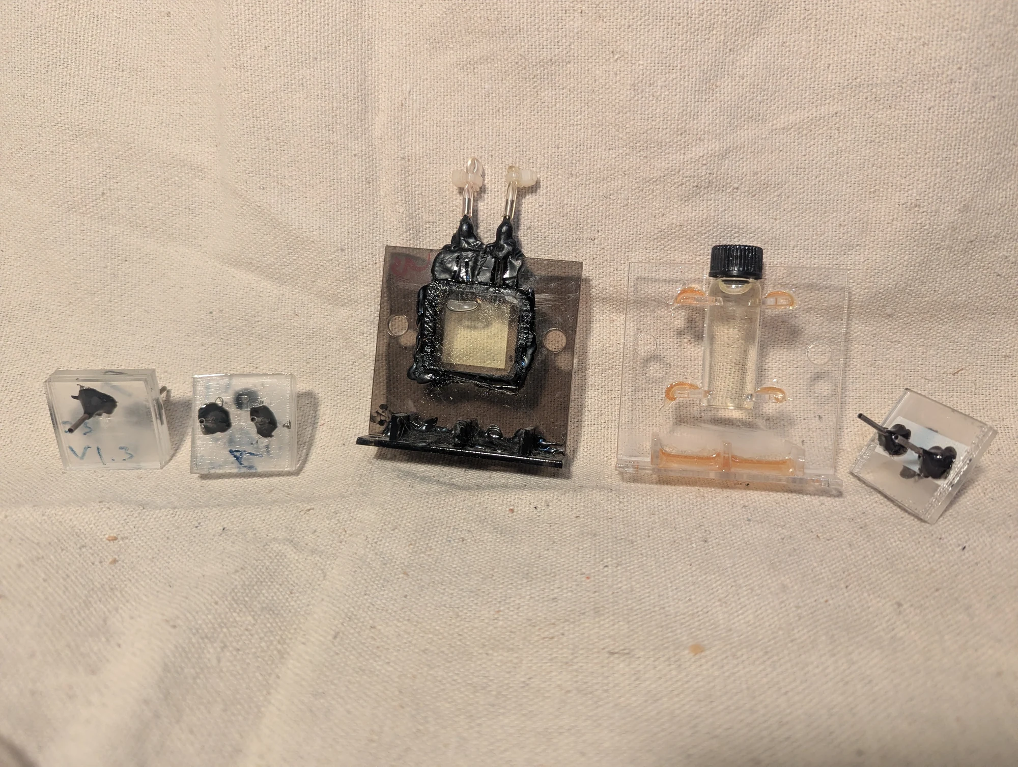
Chambers filled with virgin olive oil for a Faraday-effect experiment: investigating how a magnetic field rotates the polarization, or orientation, of light passing through a material. I used olive oil because it was available for the prototype. A material’s Verdet constant describes the strength of this response; these cells were part of the test apparatus.
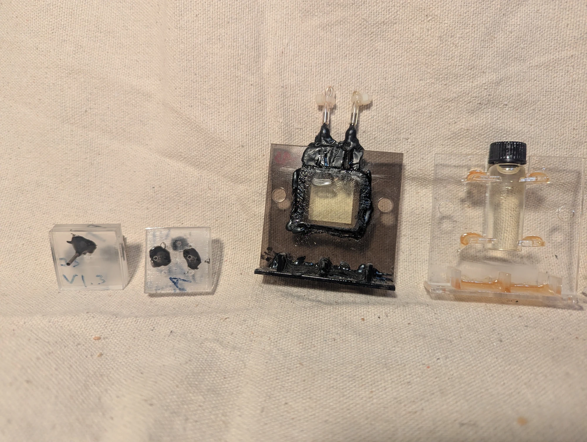
Another view of the liquid cells used in the Faraday-effect apparatus. The goal was to detect a small change in light polarization as a magnetic field was applied to the material in the light path.
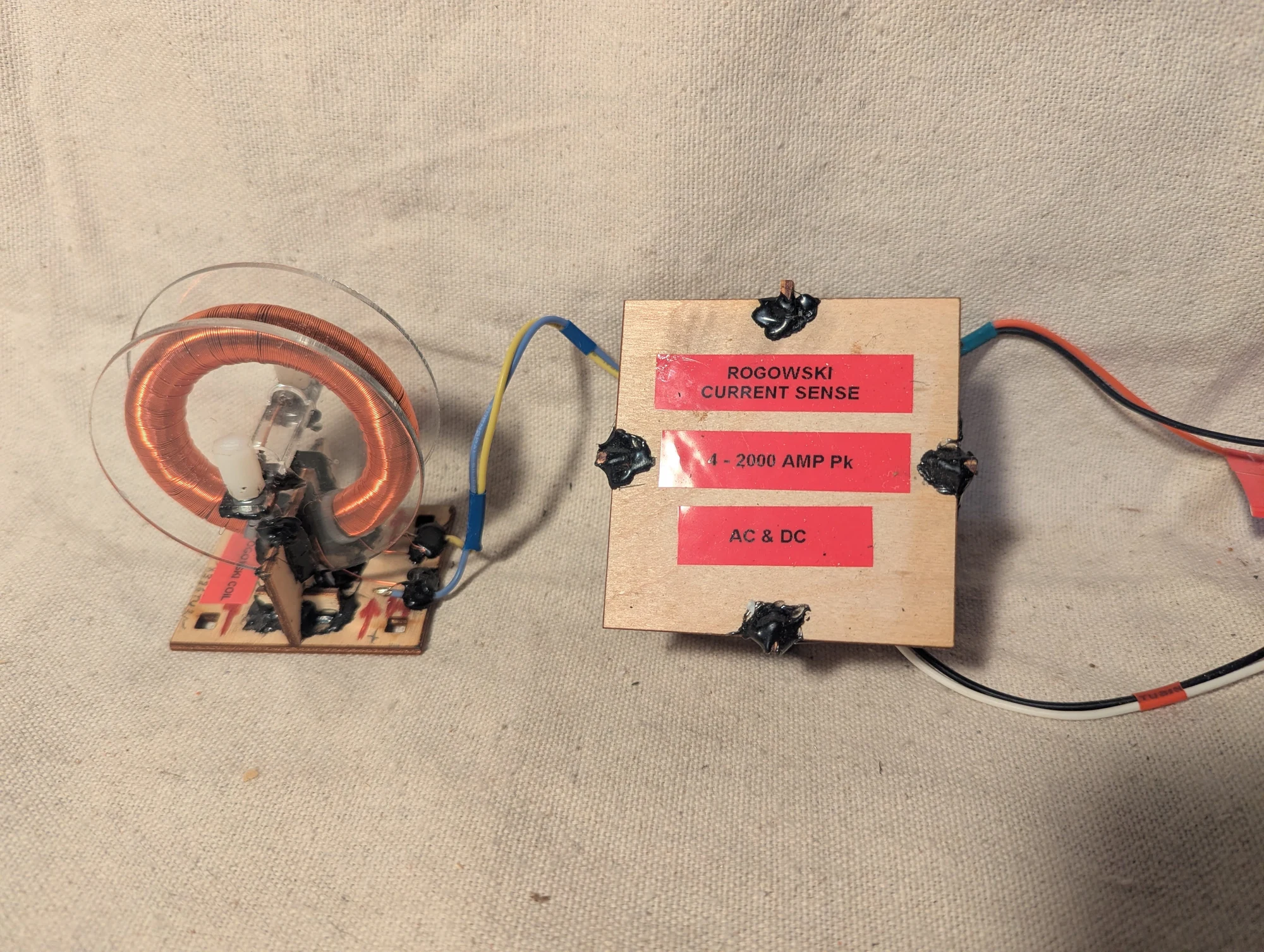
A Rogowski coil I made before I had a current transformer for pulse measurements. The conductor being measured passes through the center of the loop, and the winding picks up a signal from its changing current. Associated electronics amplified and conditioned that signal for observation with a data logger.
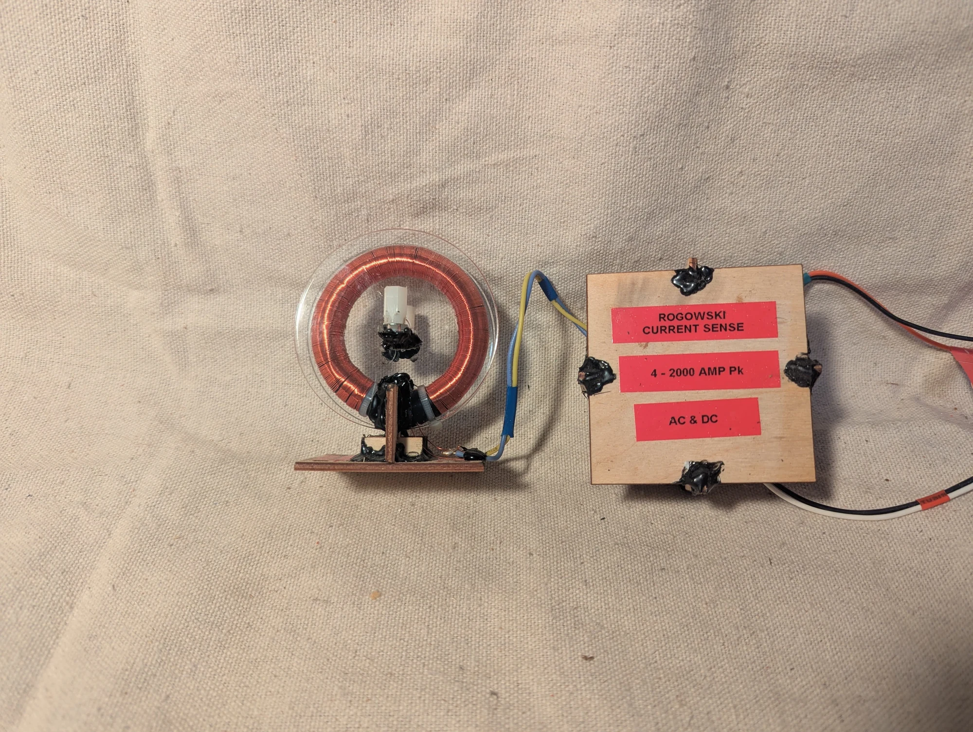
Another view of the homemade Rogowski coil and its electronics. The loop provided a way to pick up rapid changes in current through a conductor passing through its center.
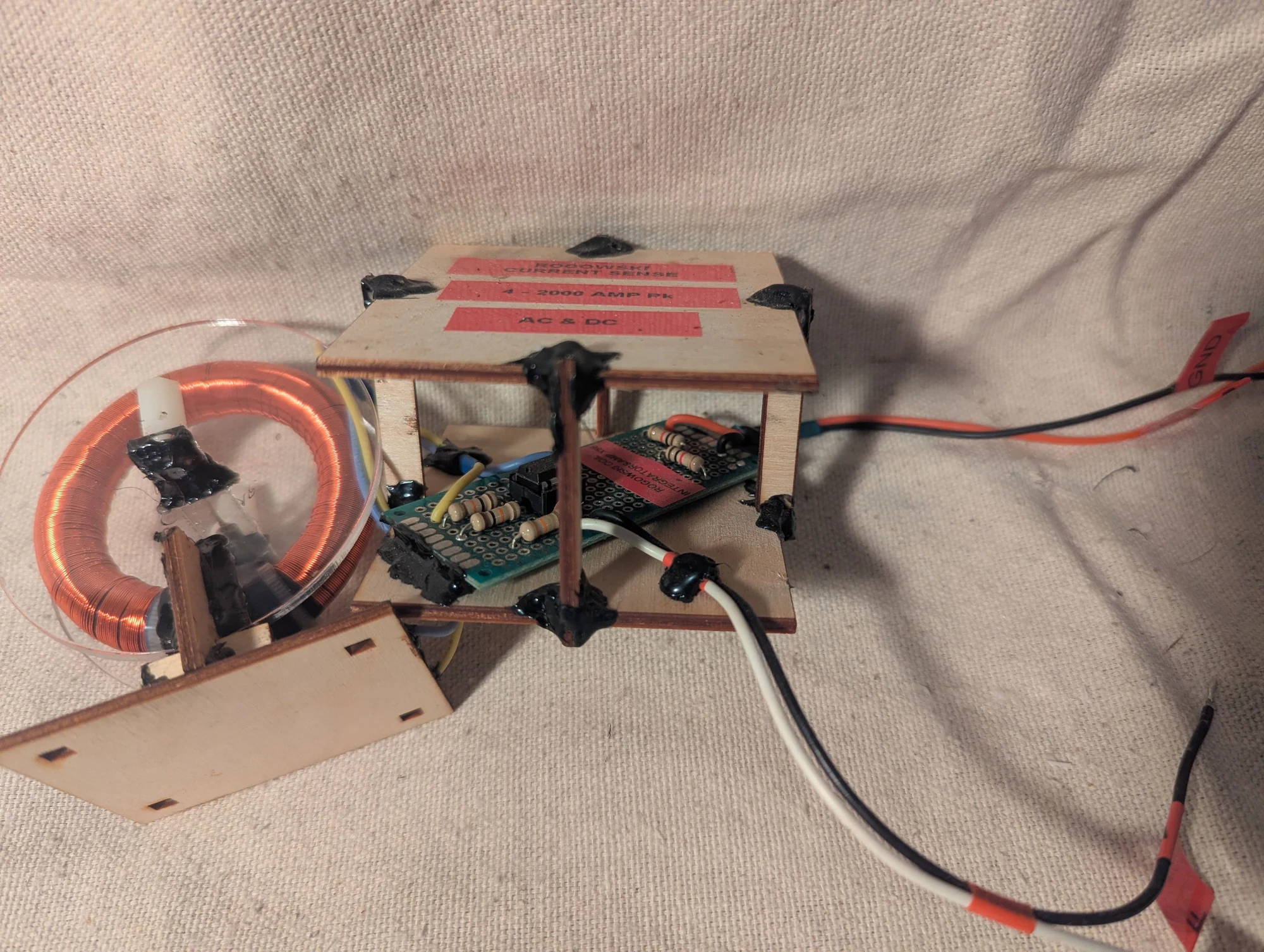
A view showing more of the amplifier and signal-conditioning electronics used with the Rogowski coil. This was part of my homemade measurement equipment for observing high-current pulses.
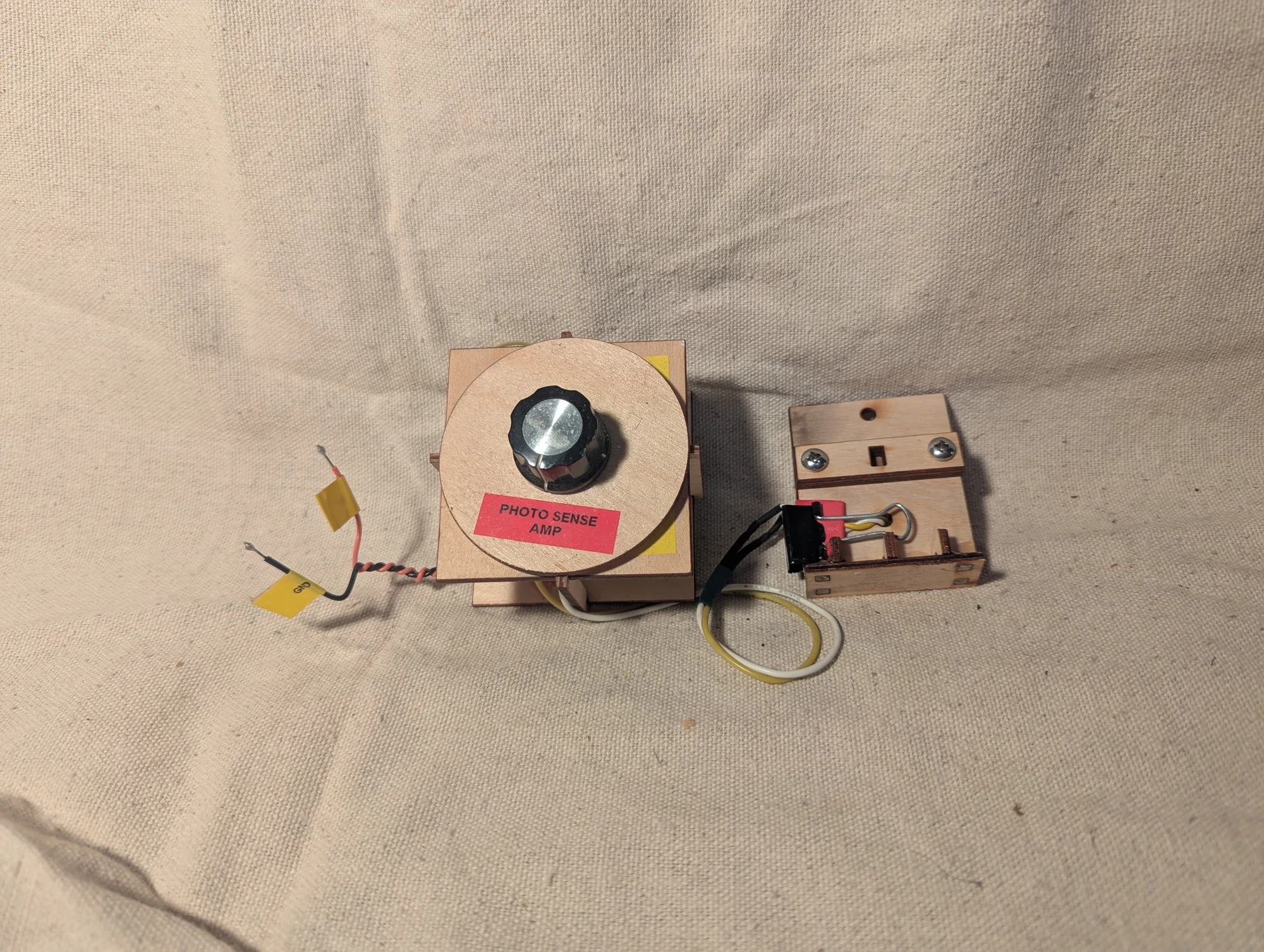
A light detector and amplifier used at the receiving end of the Faraday-effect apparatus. A polarizer before the detector converted changes in the light’s polarization into changes in brightness. The circuit amplified those small changes; I believe the sensing element was a photoresistor, though its exact type still needs confirmation.
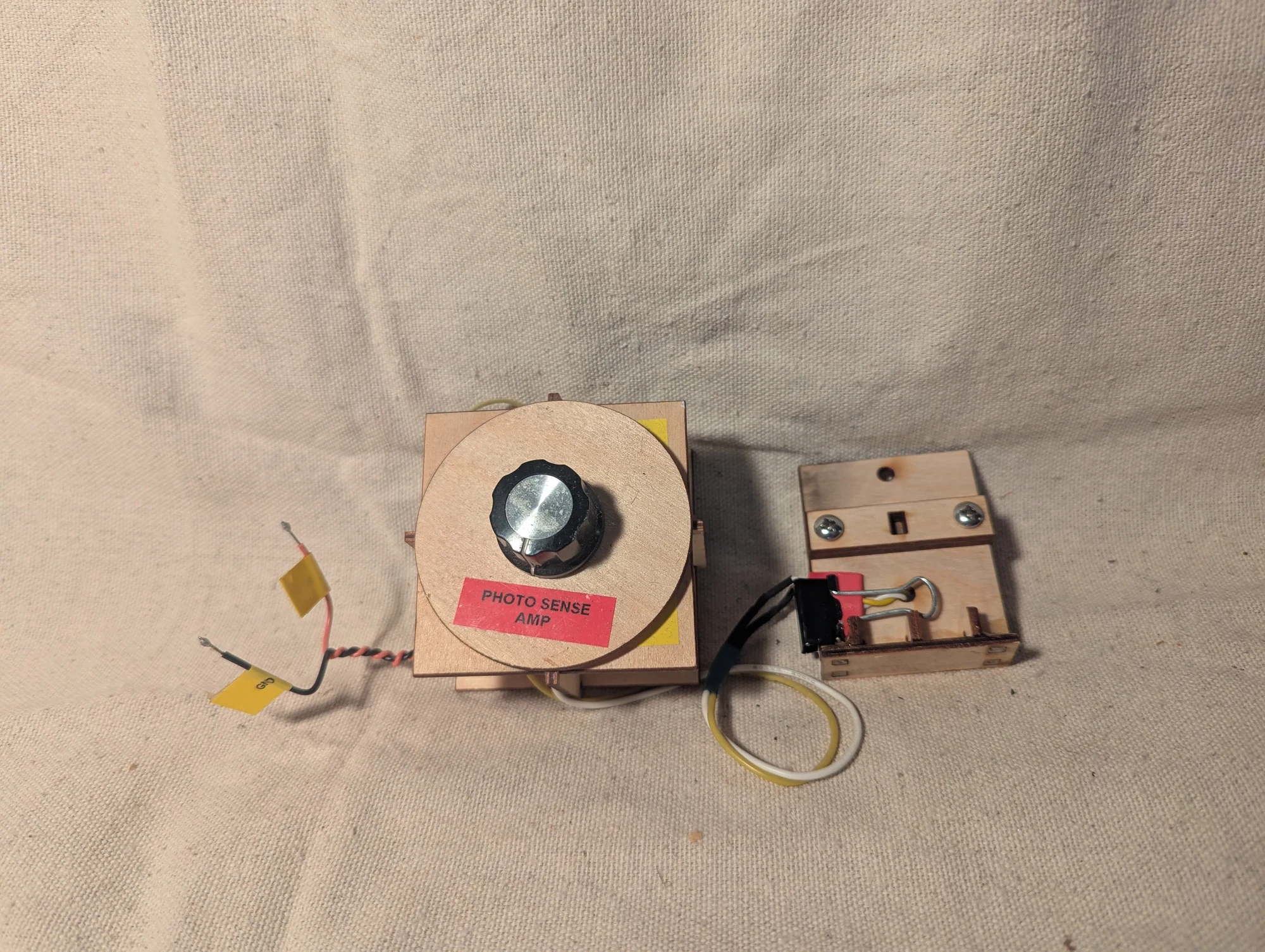
Another view of the light-sensing amplifier. It was used to look for small brightness changes after the laser beam passed through the Faraday-effect experiment and its final polarizer.
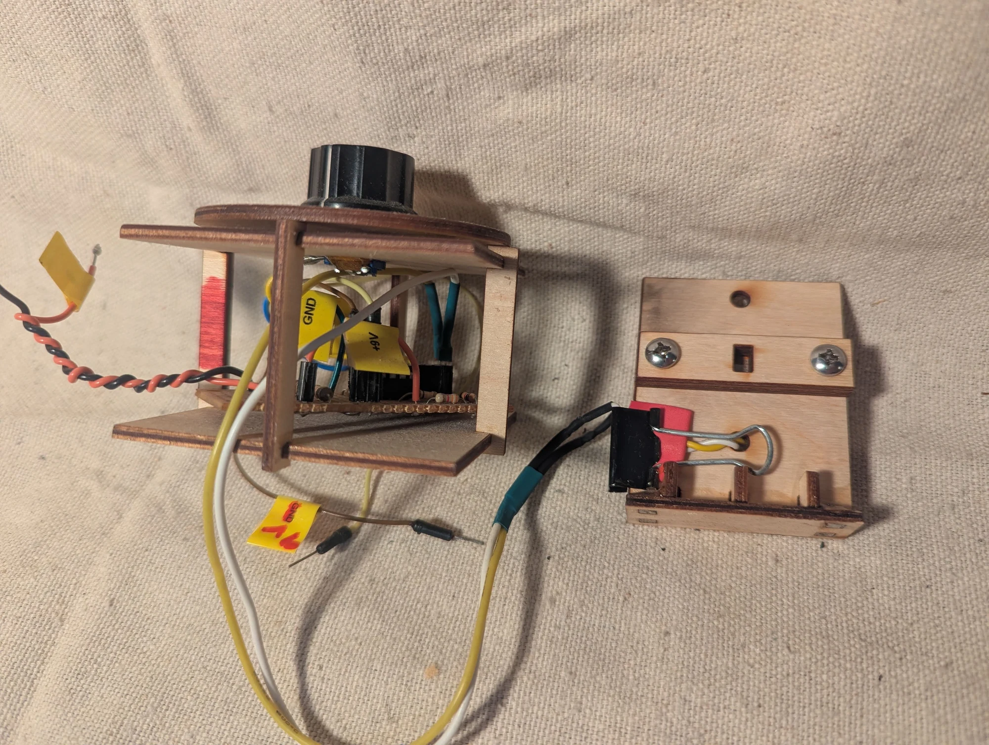
A closer view of the amplifier hardware for the optical experiment. The circuit was intended to make small changes in the detector’s signal easier to record and compare.
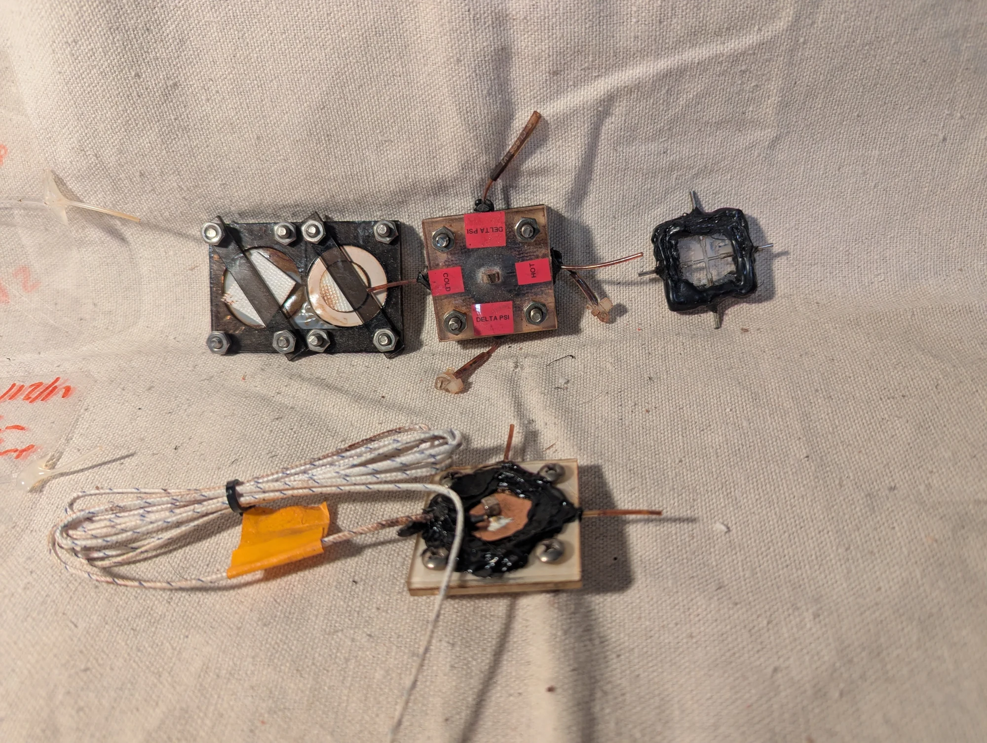
Experimental microfluidic hardware using electromagnets and thin laminated sheets. I believe this arrangement explored using magnetic motion to open or close a small fluid passage, although I no longer recall its exact configuration.
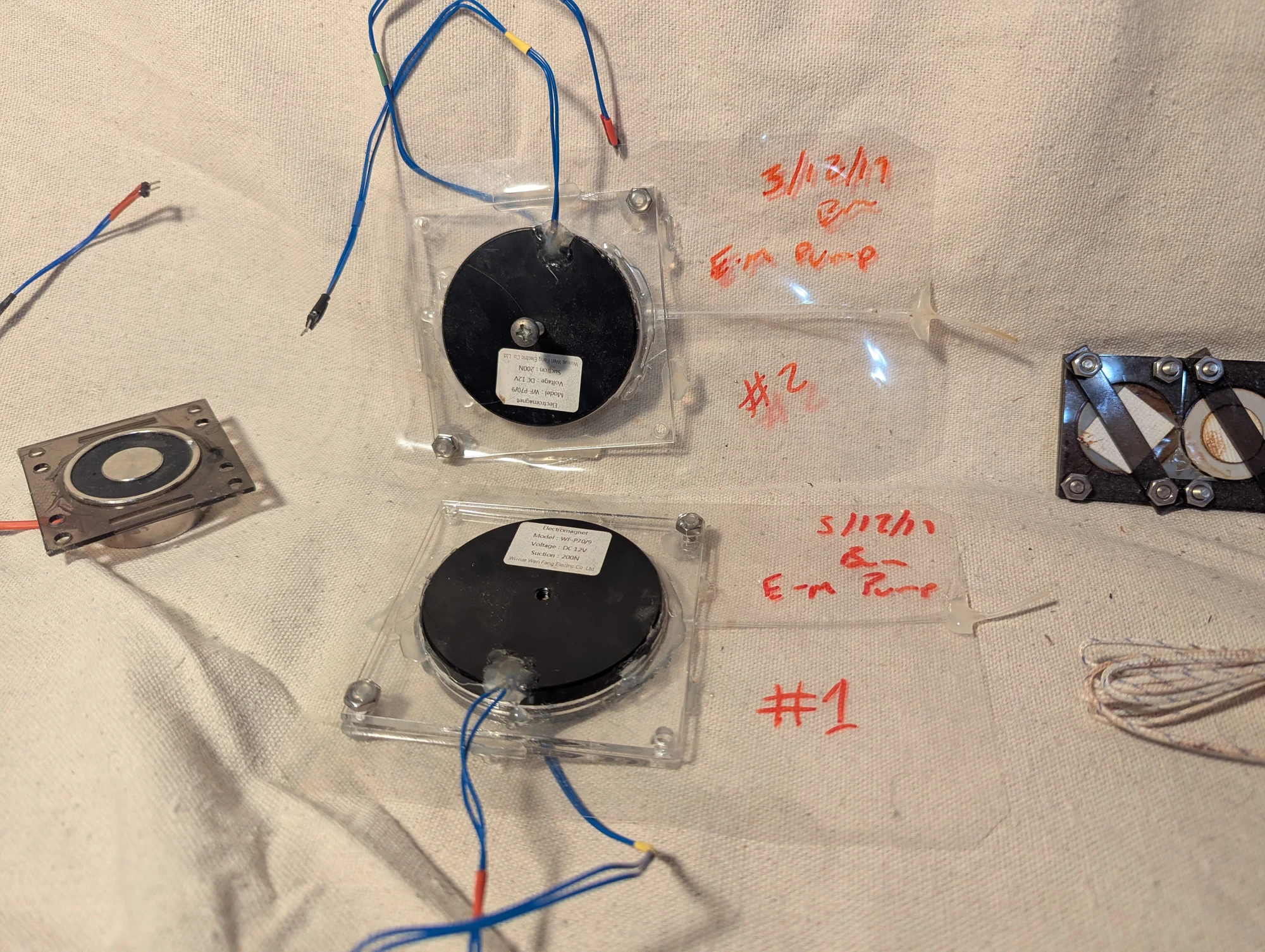
Electromagnetic pump prototypes built around a flexible pouch between laminated sheets. The idea was similar to squeezing and releasing a drink pouch: magnetic attraction compressed the chamber, while repulsion helped it reopen. This provided a way to explore pumping small amounts of fluid.
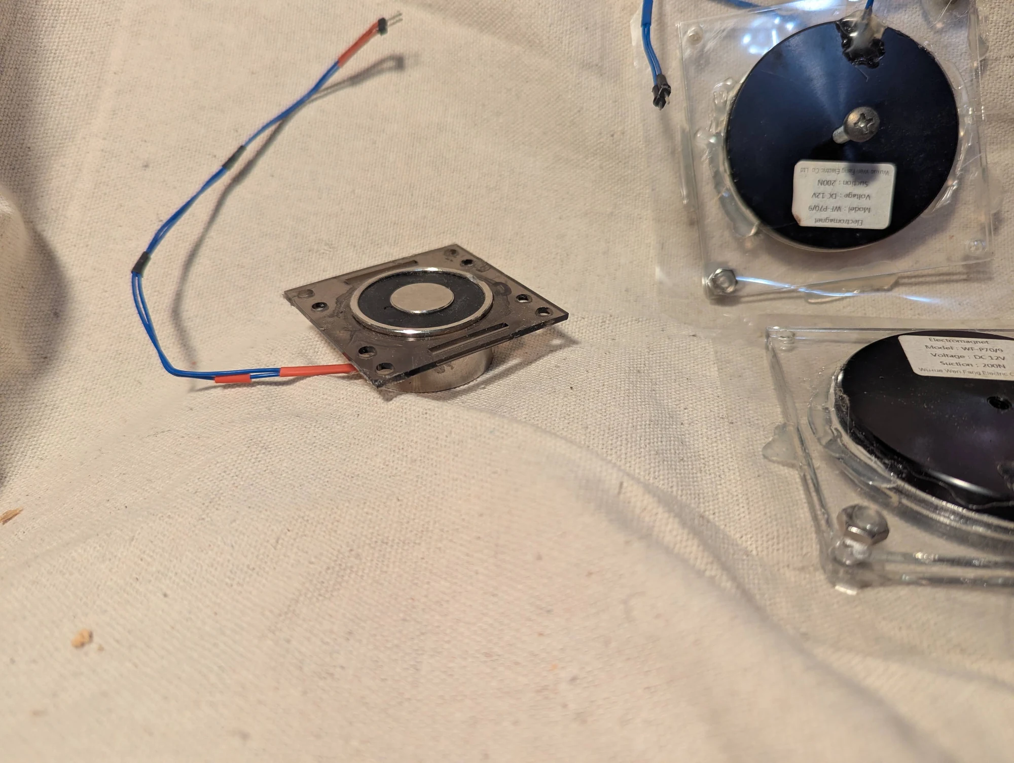
Another view of the electromagnetic components used with the laminated fluid chambers. These experiments explored how magnetic force could repeatedly compress and reopen a small flexible pouch.
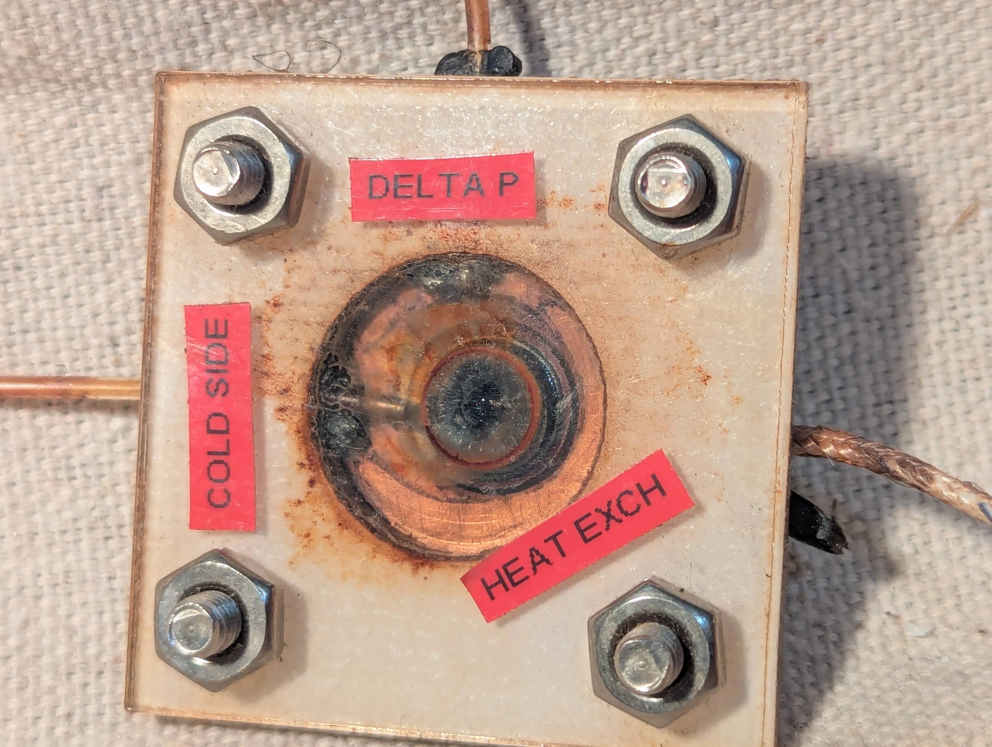
An experiment combining pressure-driven fluid movement with temperature measurements. Tygon tubes accessed positions close to the strongest part of the magnetic field and farther away. I was exploring whether these locations would contain fluid at different temperatures, and whether moving that fluid could transfer heat. The thermocouples were used to look for the resulting changes.
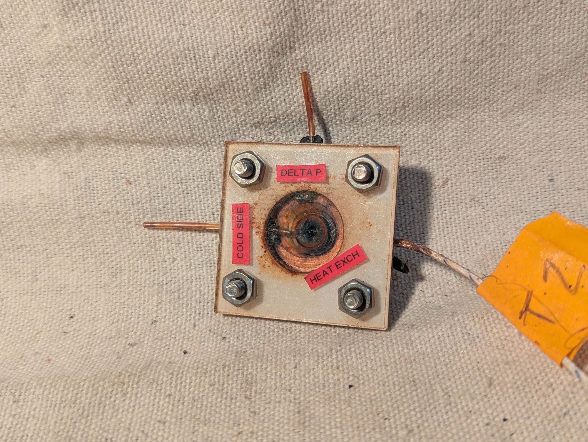
Another view of the chamber used to explore temperature differences and pressure-driven heat transfer in ferrofluid. The positions of the fluid connections were chosen to compare regions nearer to and farther from the strongest magnetic field.
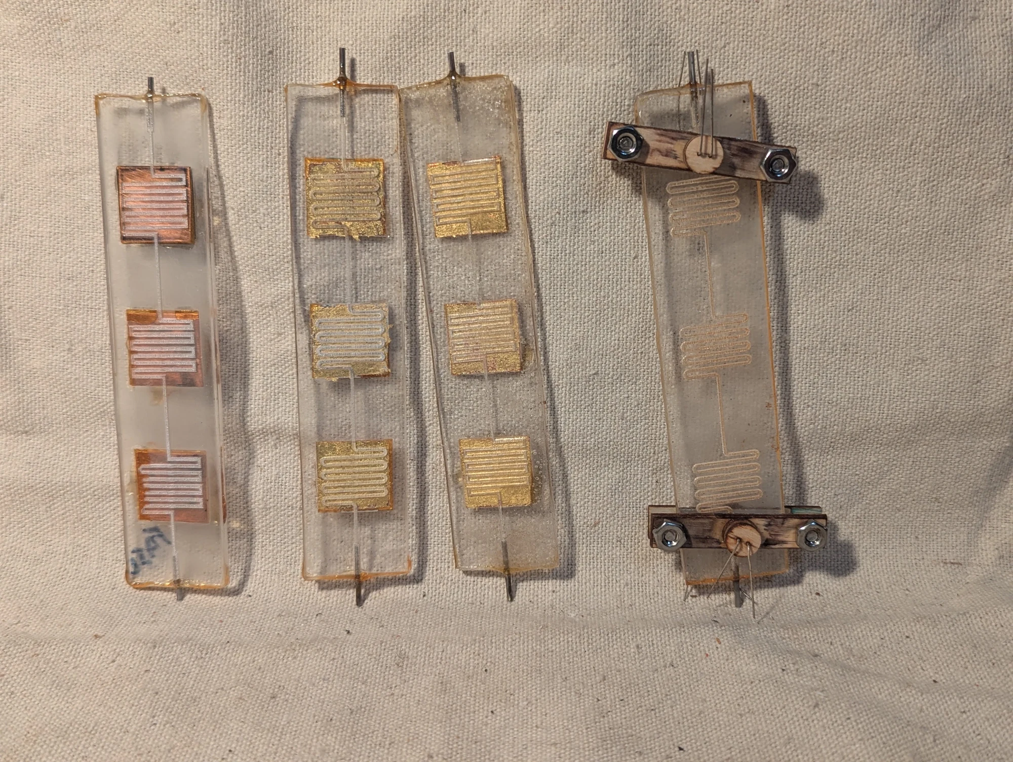
Microfluidic heat-exchanger prototypes with metal plates embedded in acrylic. Serpentine channels guided the fluid across copper surfaces before it left the device. Some plates were covered with gold foil in an effort to reduce chemical interaction with the fluid. The collection also includes an earlier test assembly.
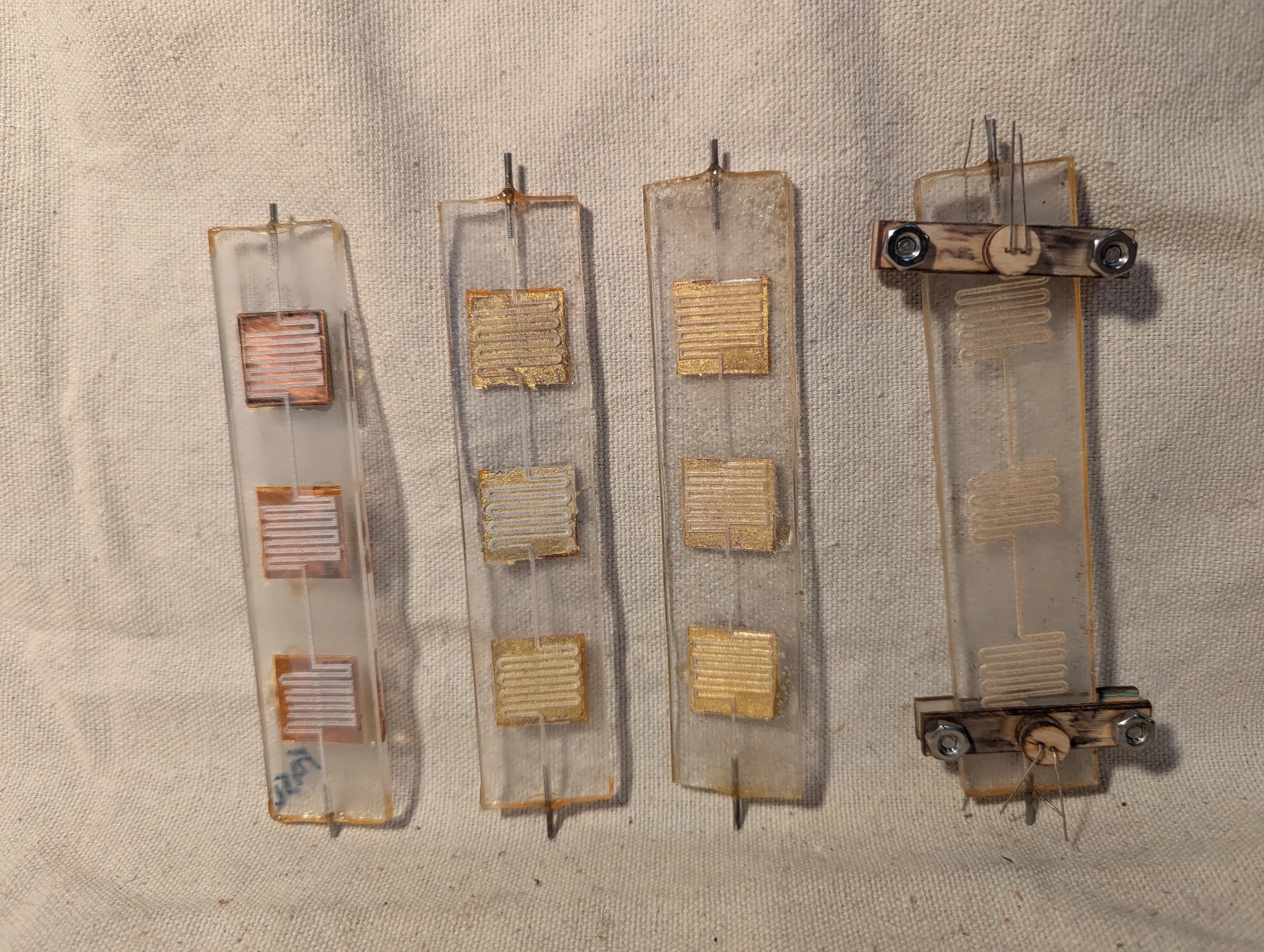
Another view of the acrylic heat-exchanger prototypes. The winding channels were intended to keep fluid in contact with the embedded metal surfaces along a longer path, allowing me to explore controlled heat transfer on a small scale.
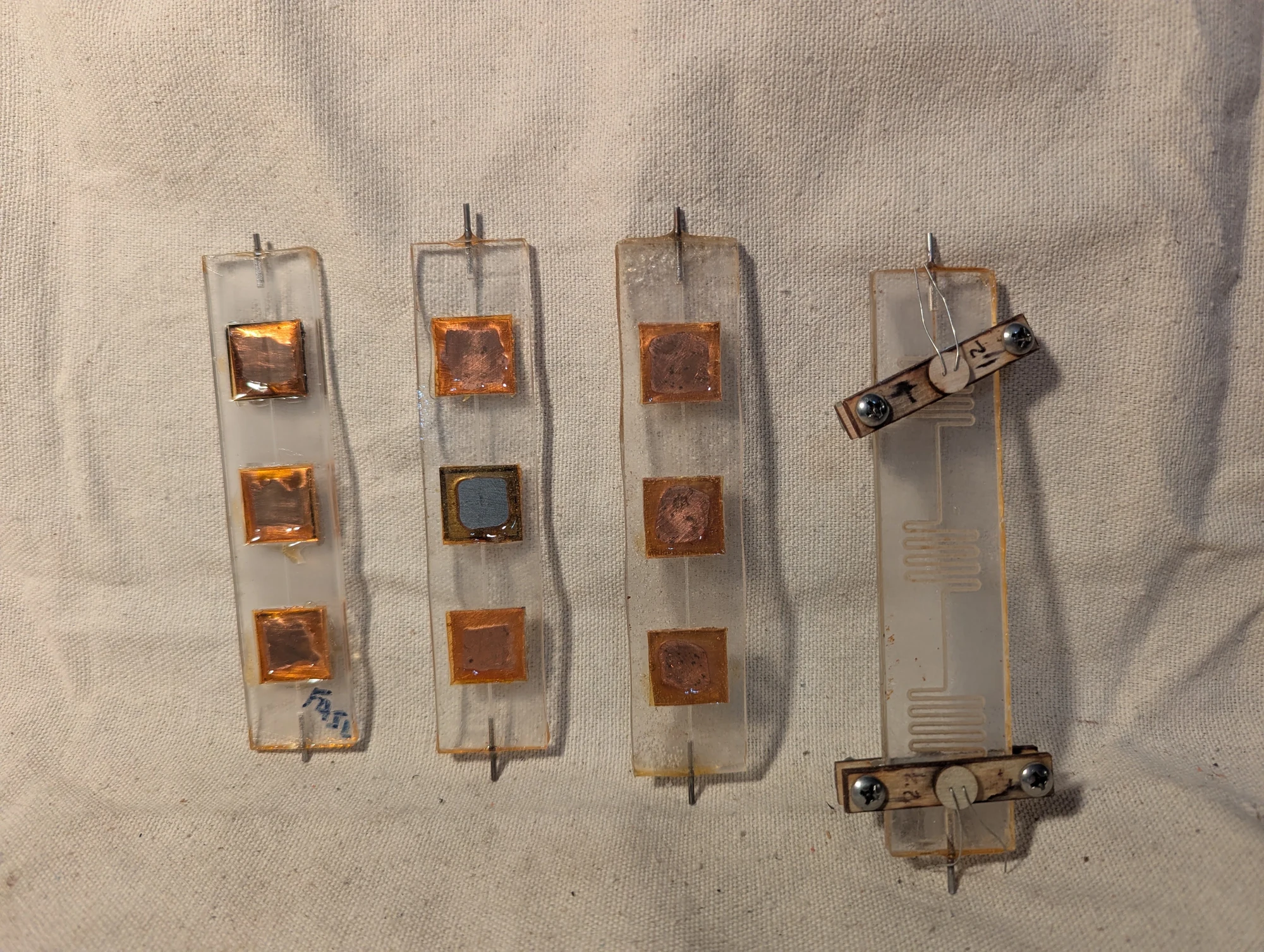
A further view of the heat-exchanger collection, showing several plate and channel arrangements. I used these experimental assemblies to explore moving heat between ferrofluid and metal surfaces, with different paths guiding the fluid across the plates.
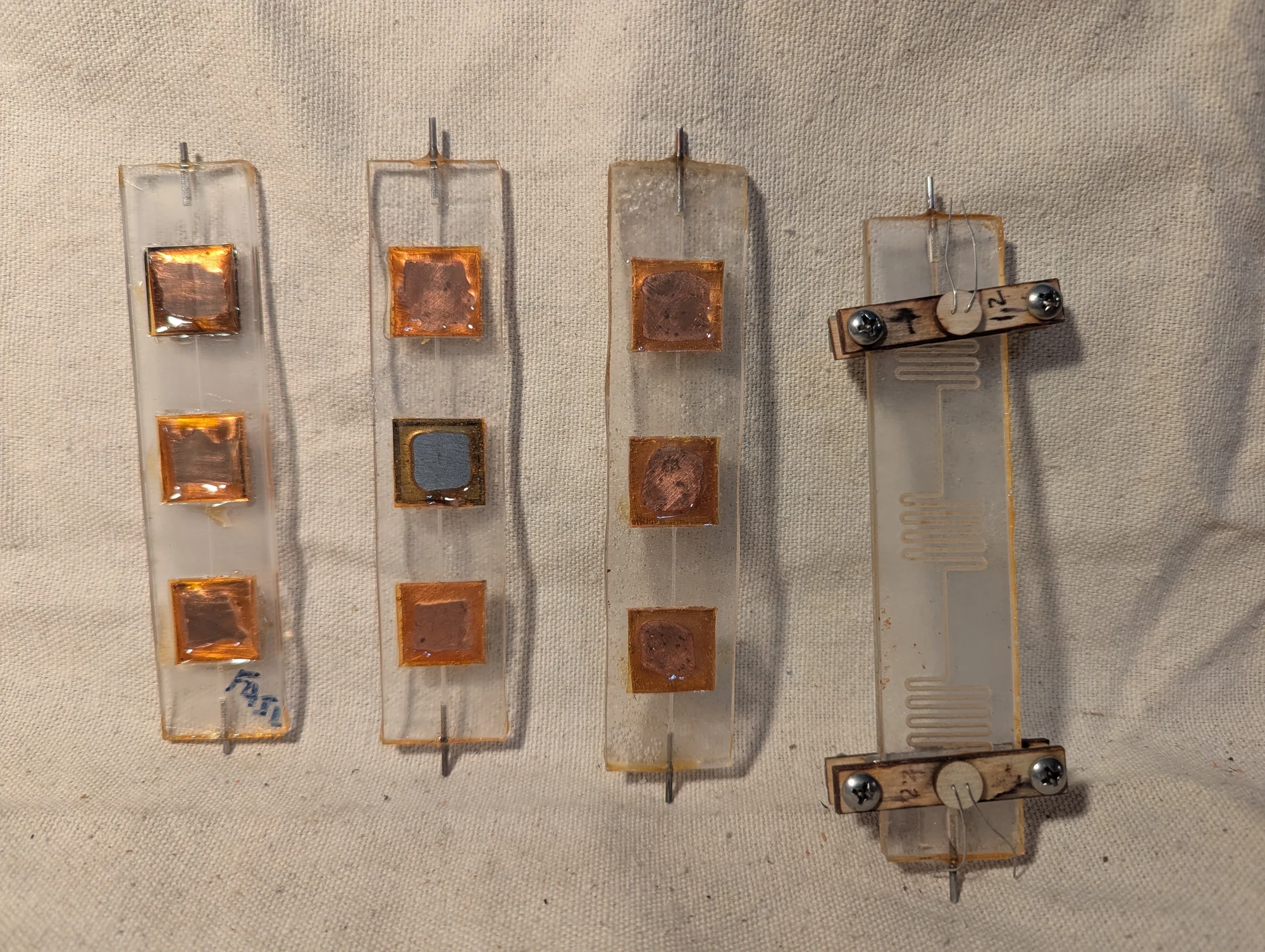
Another view of the heat-exchanger experiments. One version may have used a gadolinium plate between copper plates: the idea was to expose the gadolinium to a magnetic field, then move the fluid above it toward either copper plate and measure the temperature change. Looking back, I suspect the copper’s mass was too large for such a small amount of ferrofluid to produce a measurable temperature change.
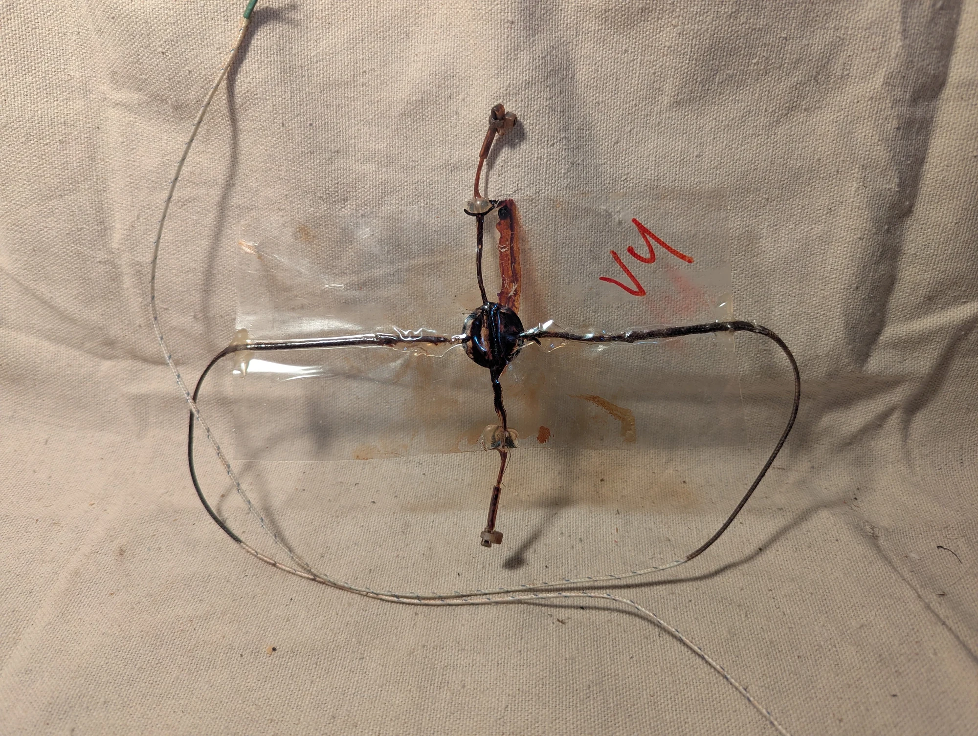
A test piece for making a four-way fluid junction from thin laminated sheets. It was part of my work on lightweight channels for ferrofluid and other microfluidic experiments.
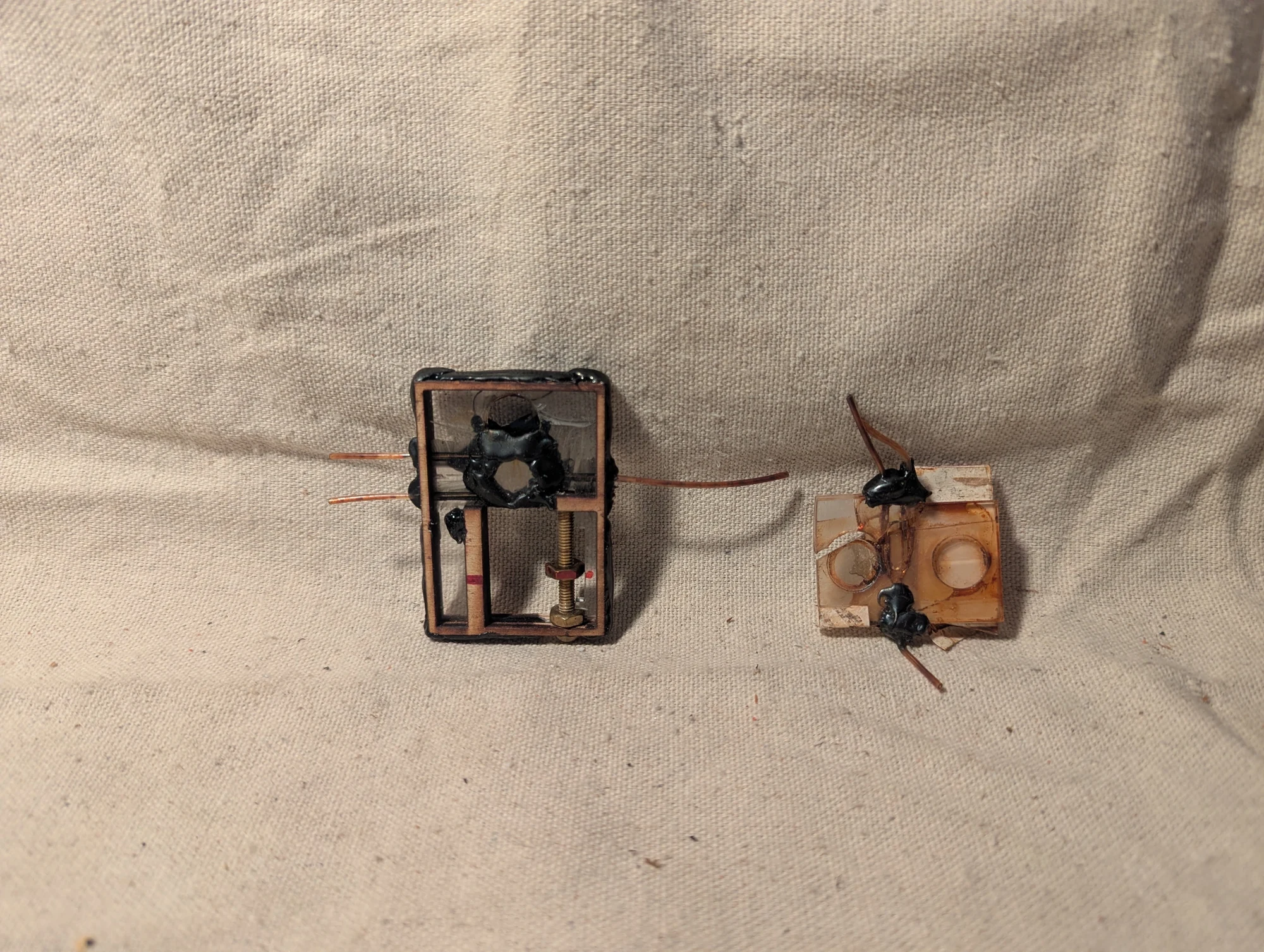
I have grouped this adjustable experimental assembly with my microfluidics work. I no longer recall its exact purpose.
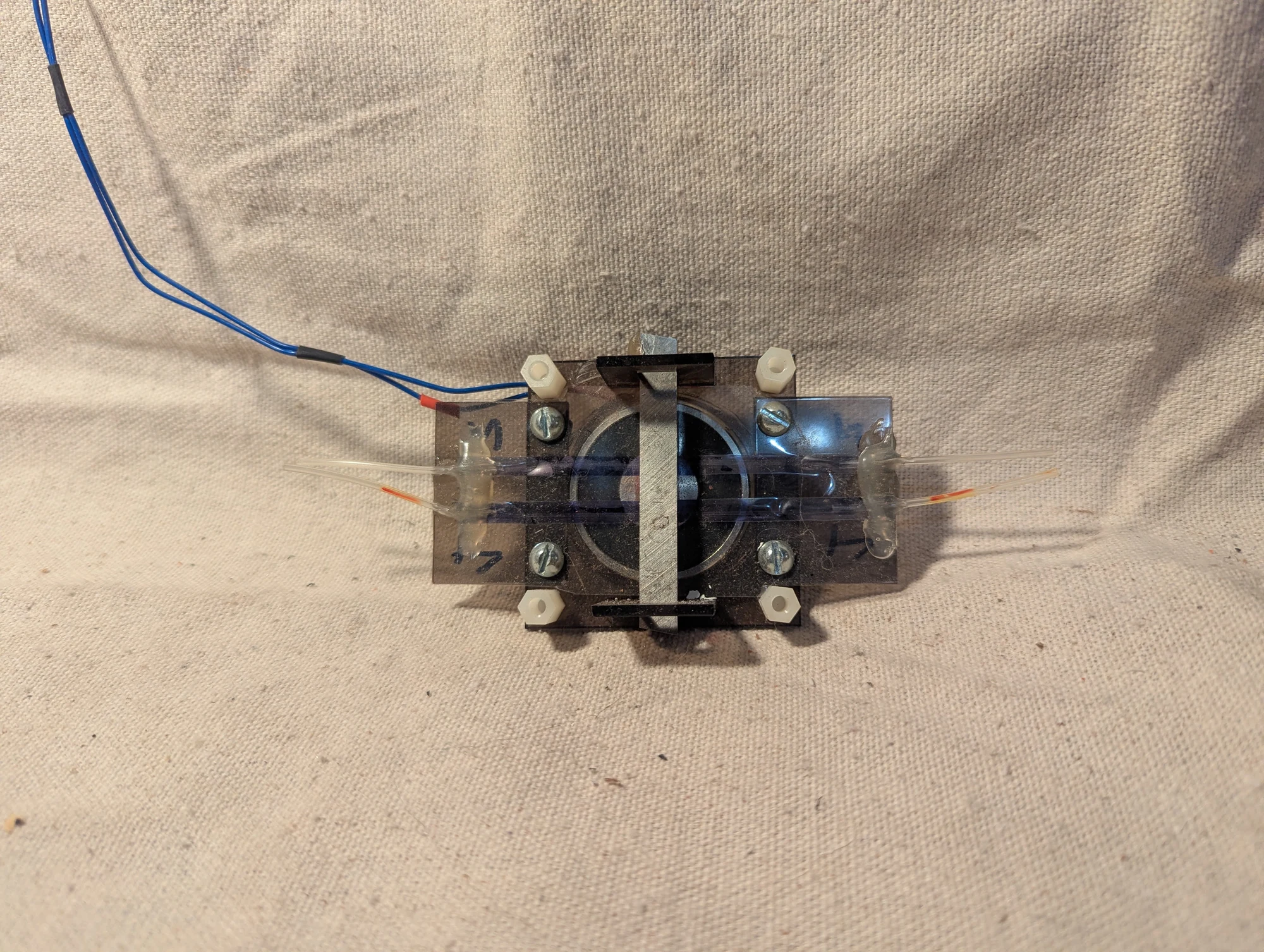
An electrically controlled valve for thin, flat channels made from laminated sheets. An electromagnet pulls a steel bar against the channel, pinching it closed to stop fluid flow.
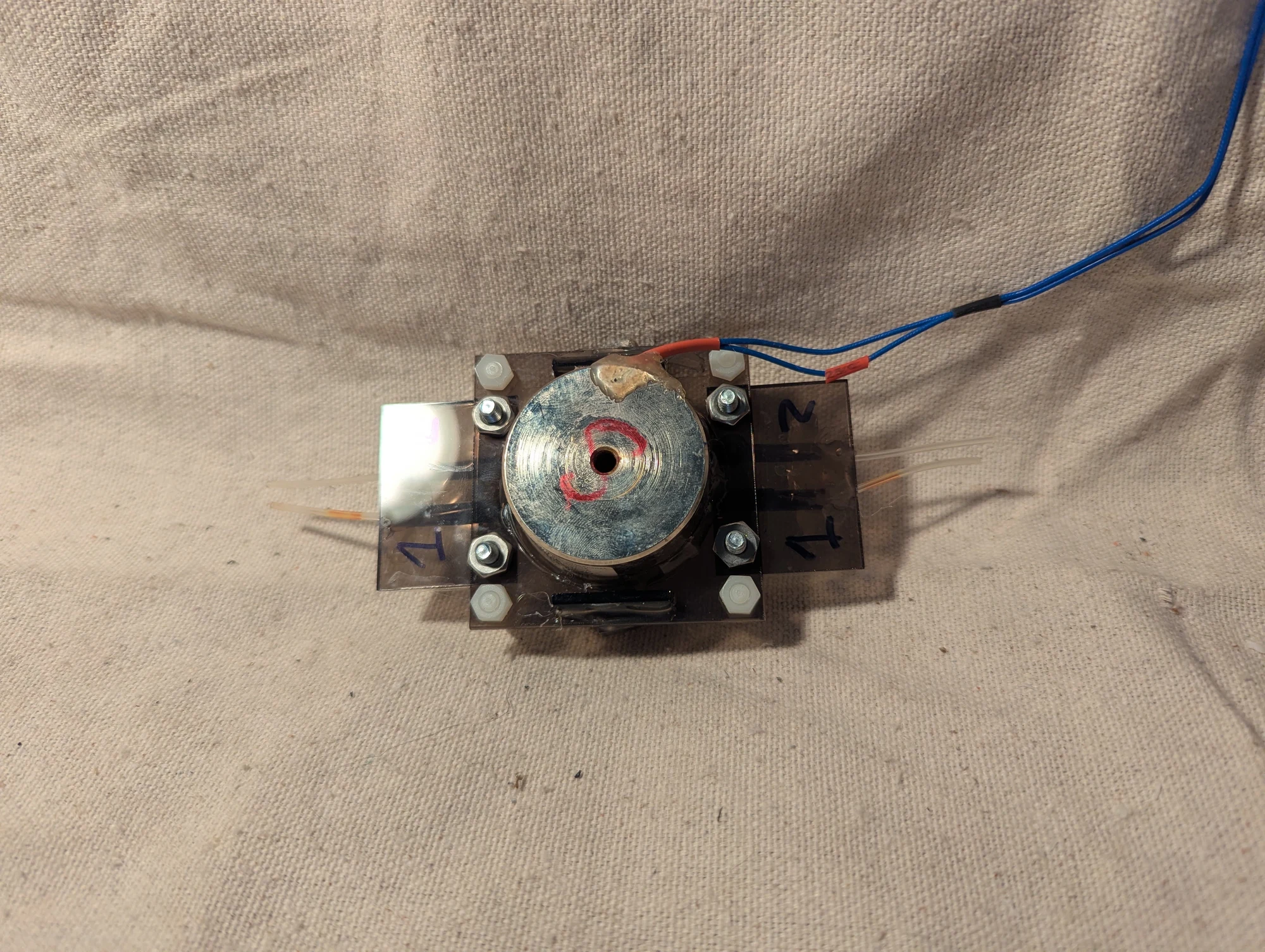
A rear view of the electromagnetic valve shown in Photo 417, revealing more of the actuator and supporting structure.
Photos 422–496
Batch 08 · 68 photographs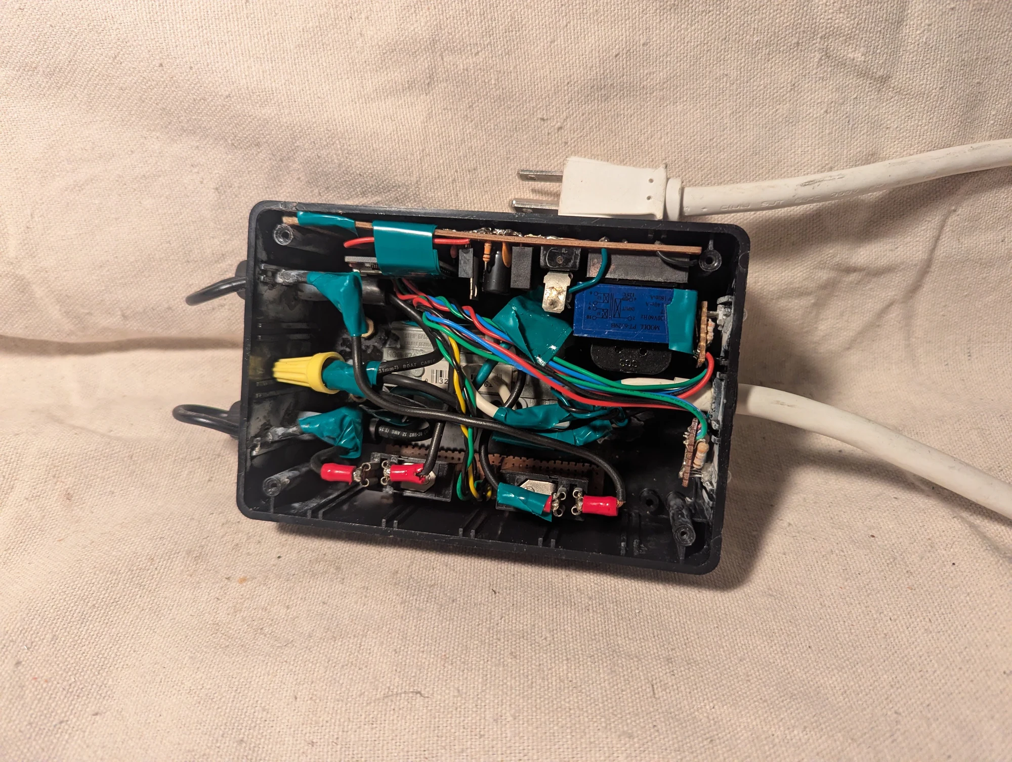
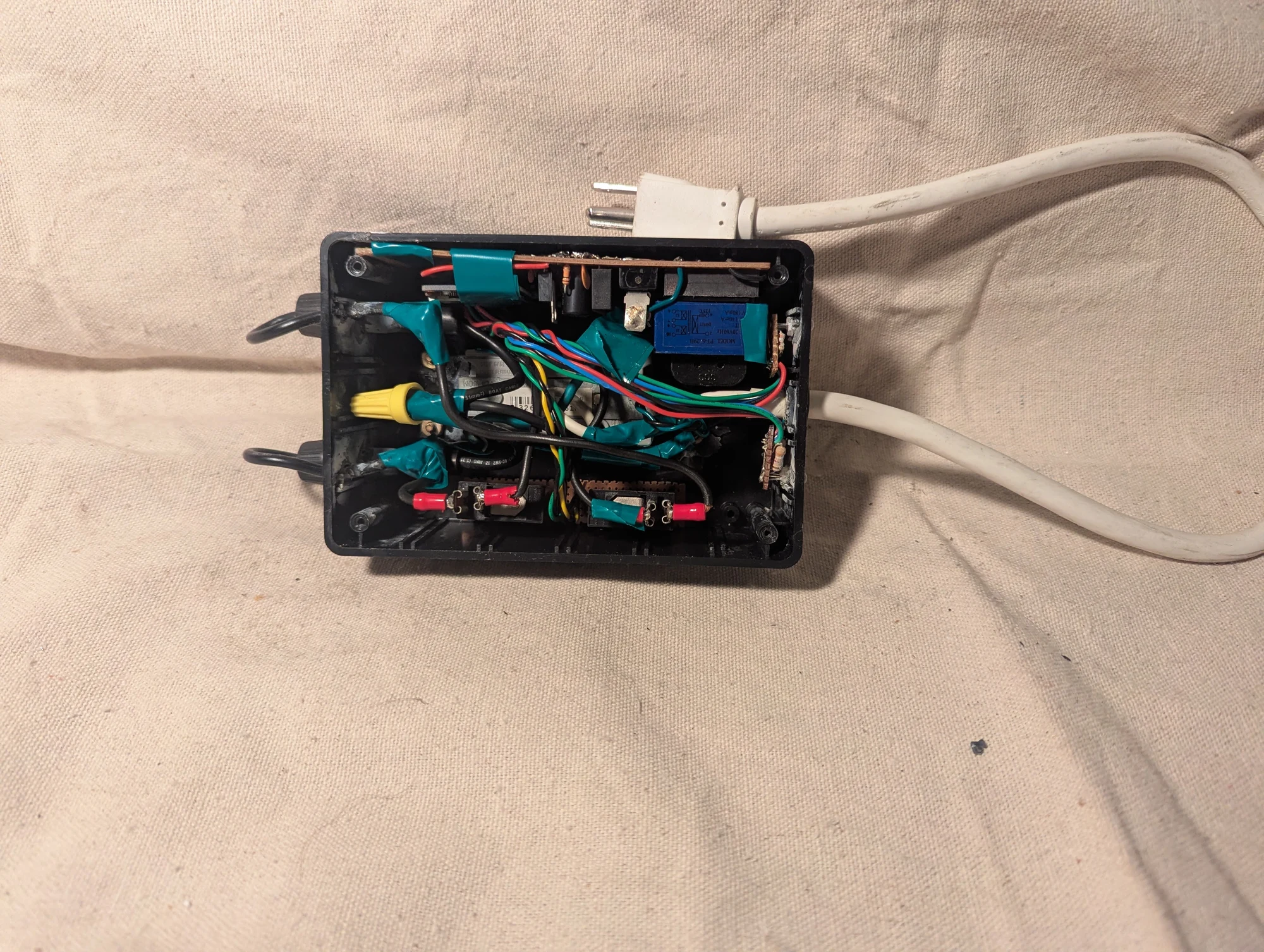
A Bluetooth-controlled outlet I built around 2016–2017. A phone app could switch the outlet on or off, and an LED indicated its state. This view shows the electronics inside the enclosure.
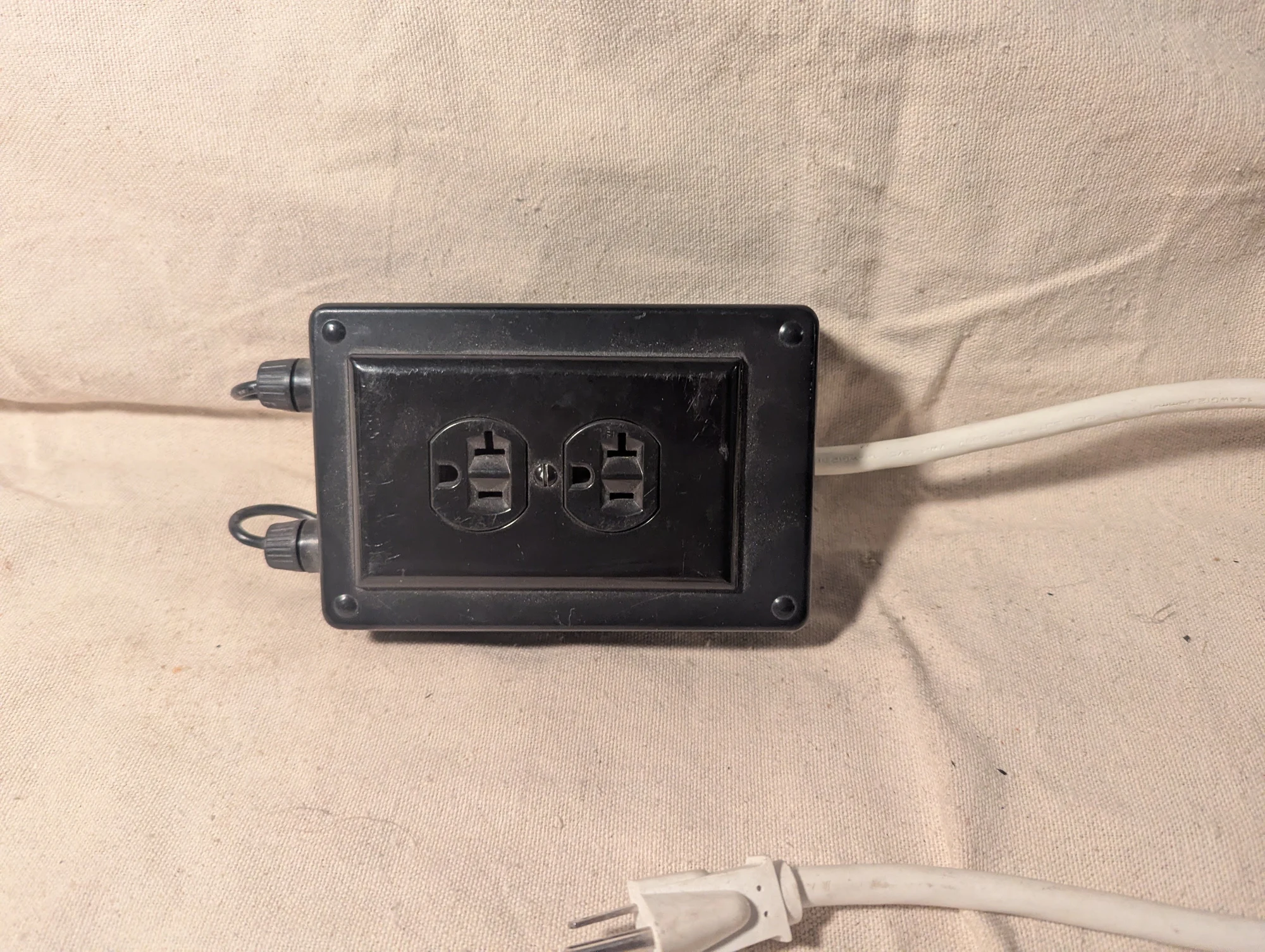
Another view inside the Bluetooth-controlled outlet. The project combined phone-based switching with a local LED indication of the outlet’s state.
The exterior of the phone-controlled power outlet, with its electronics housed inside the enclosure.
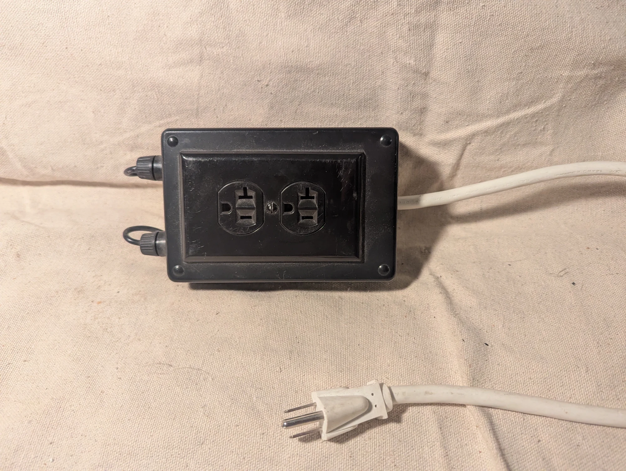
Another photograph of the completed enclosure for the Bluetooth-controlled outlet.
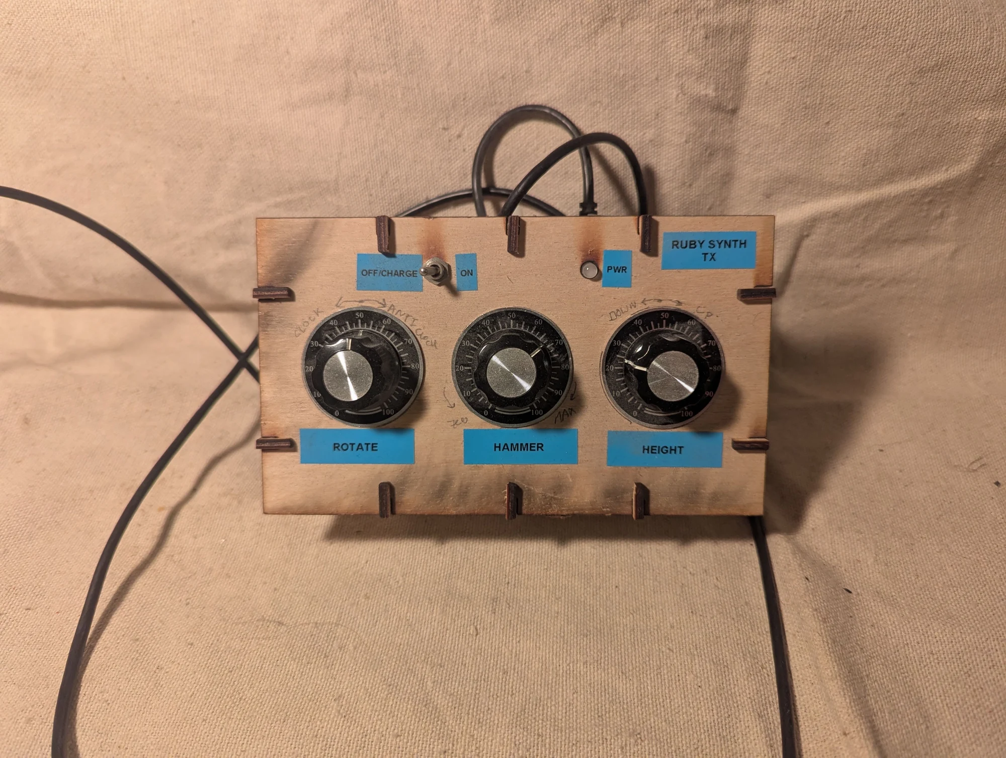
A remote controller for a mechanism in an early ruby project. The mechanism combined rotation with vertical movement, raising or lowering a small piston-like part while it turned. Remote operation let me control the motion from farther away while the high-voltage, high-power equipment was running.
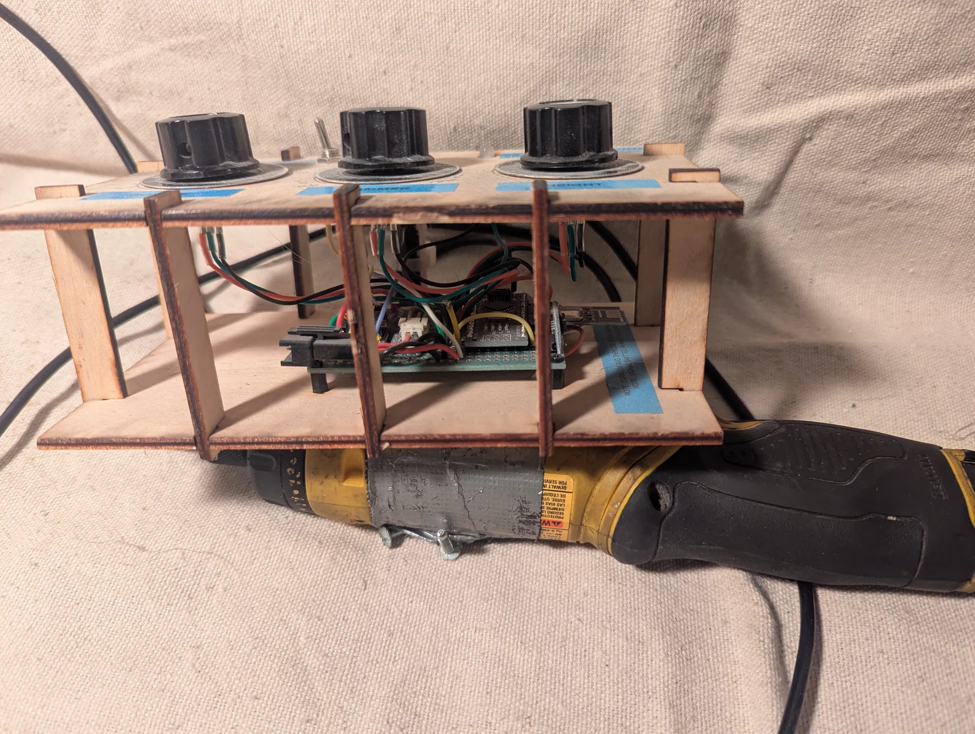
Another angle on the remote controller and its supporting frame. It controlled the combined rotating and lifting motion used in the earlier ruby experiment.
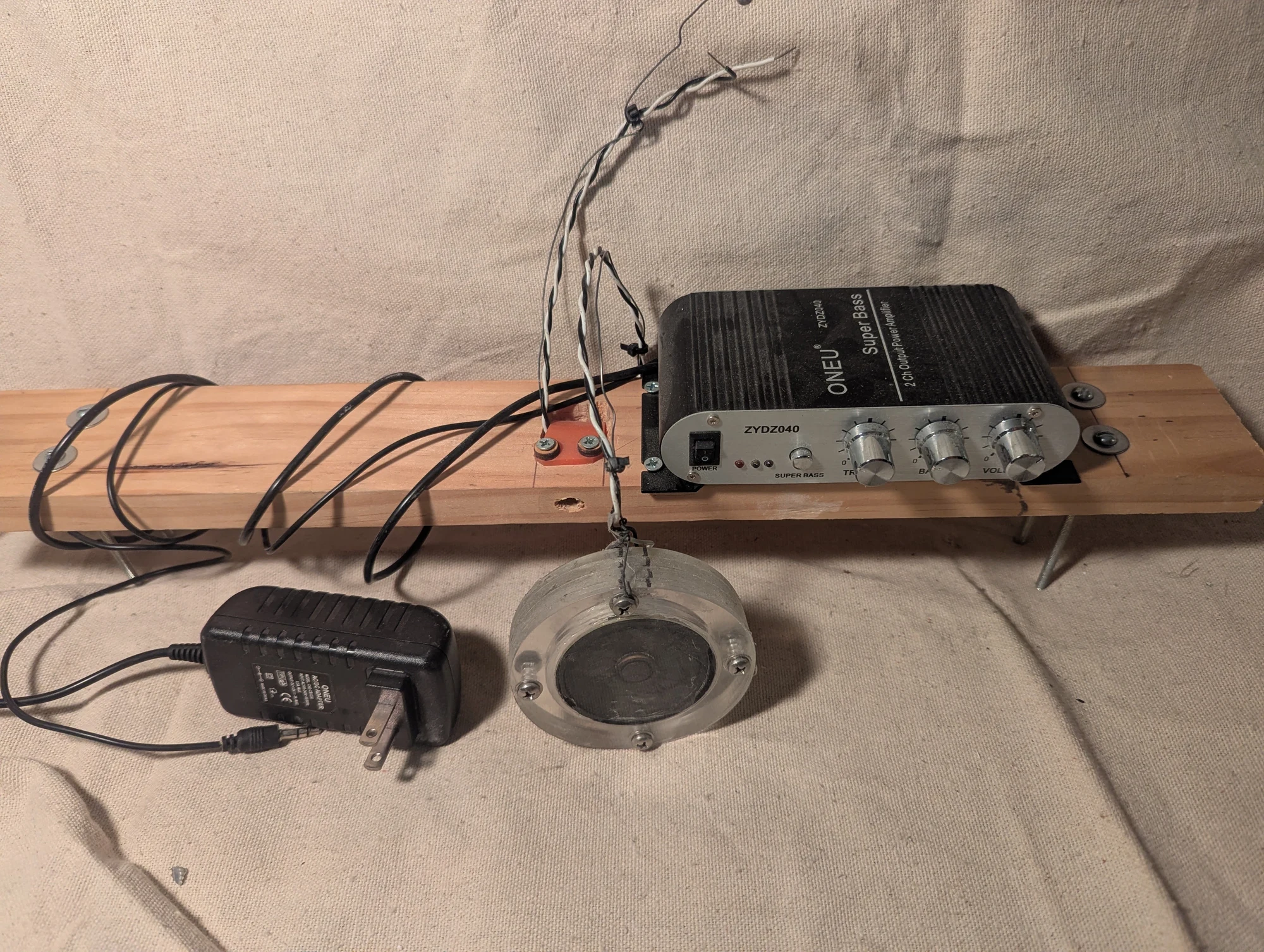
An underwater transducer and its supporting test equipment. I used it as a sound source when testing underwater microphones.
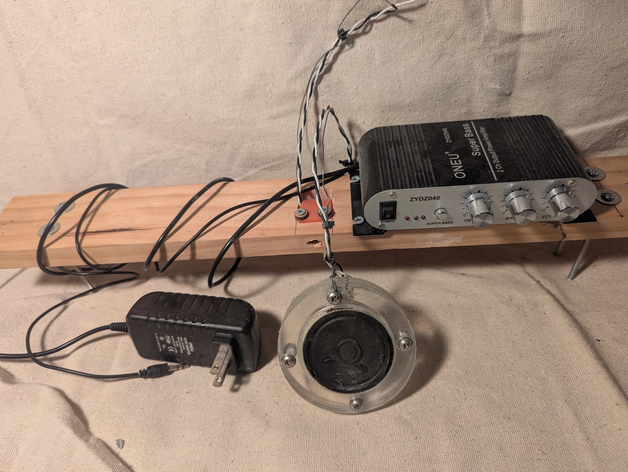
Another view of the transducer setup used to test underwater microphones.
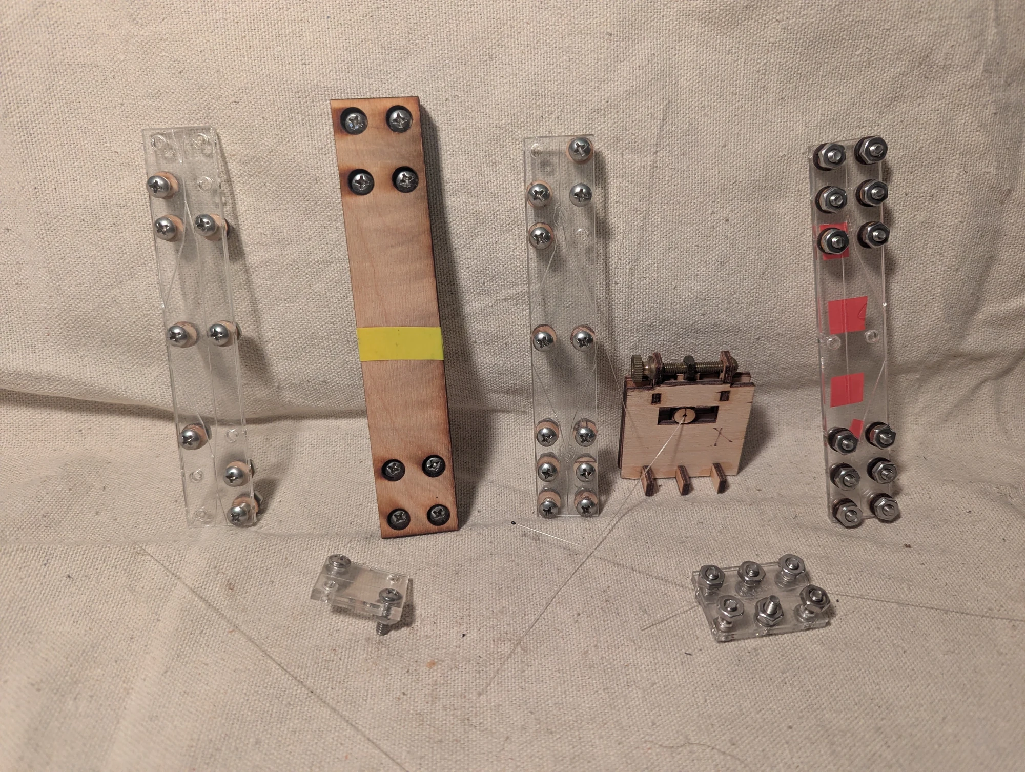
Experimental components for a fiber-optic interferometer. Engraved channels in acrylic plates held the fibers in position while I explored ways to split and combine their light signals. The fiber ends were placed against one another with index-matching gel intended to improve light transfer across the joints.
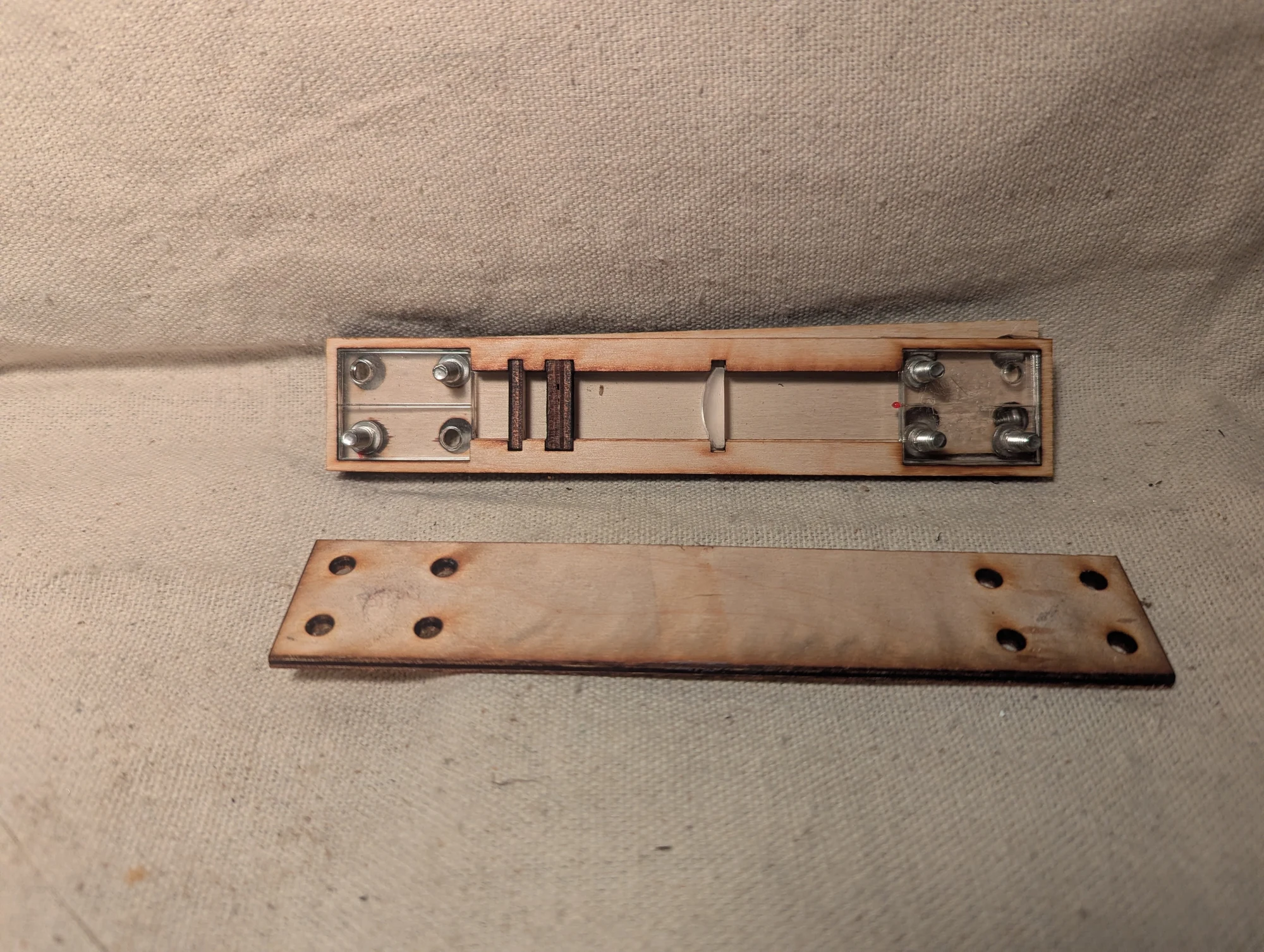
One fiber carried ultraviolet light to an epoxy bead containing fluorescent dye, causing the bead to emit colored light. A small lens was intended to collect that light and focus it onto the end of a second fiber. This prototype explored coupling the fluorescent output back into an optical fiber.
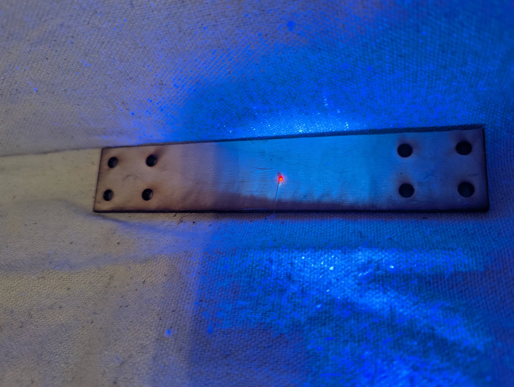
The epoxy bead glowing under ultraviolet illumination. Its reddish fluorescence shows the light-emitting material used in the fiber-coupling experiment.
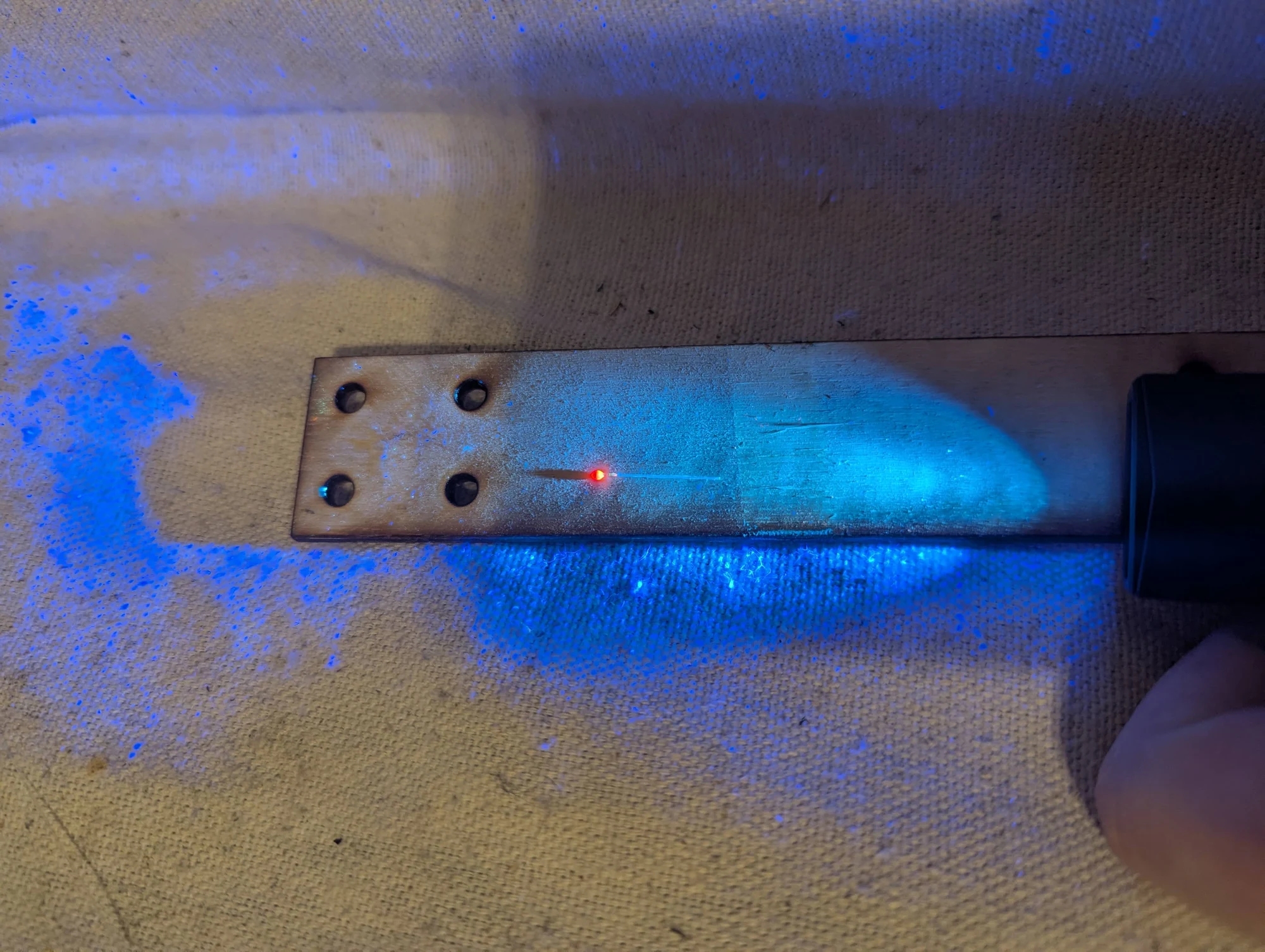
Another view of the fluorescent bead under ultraviolet illumination, within the optical assembly.
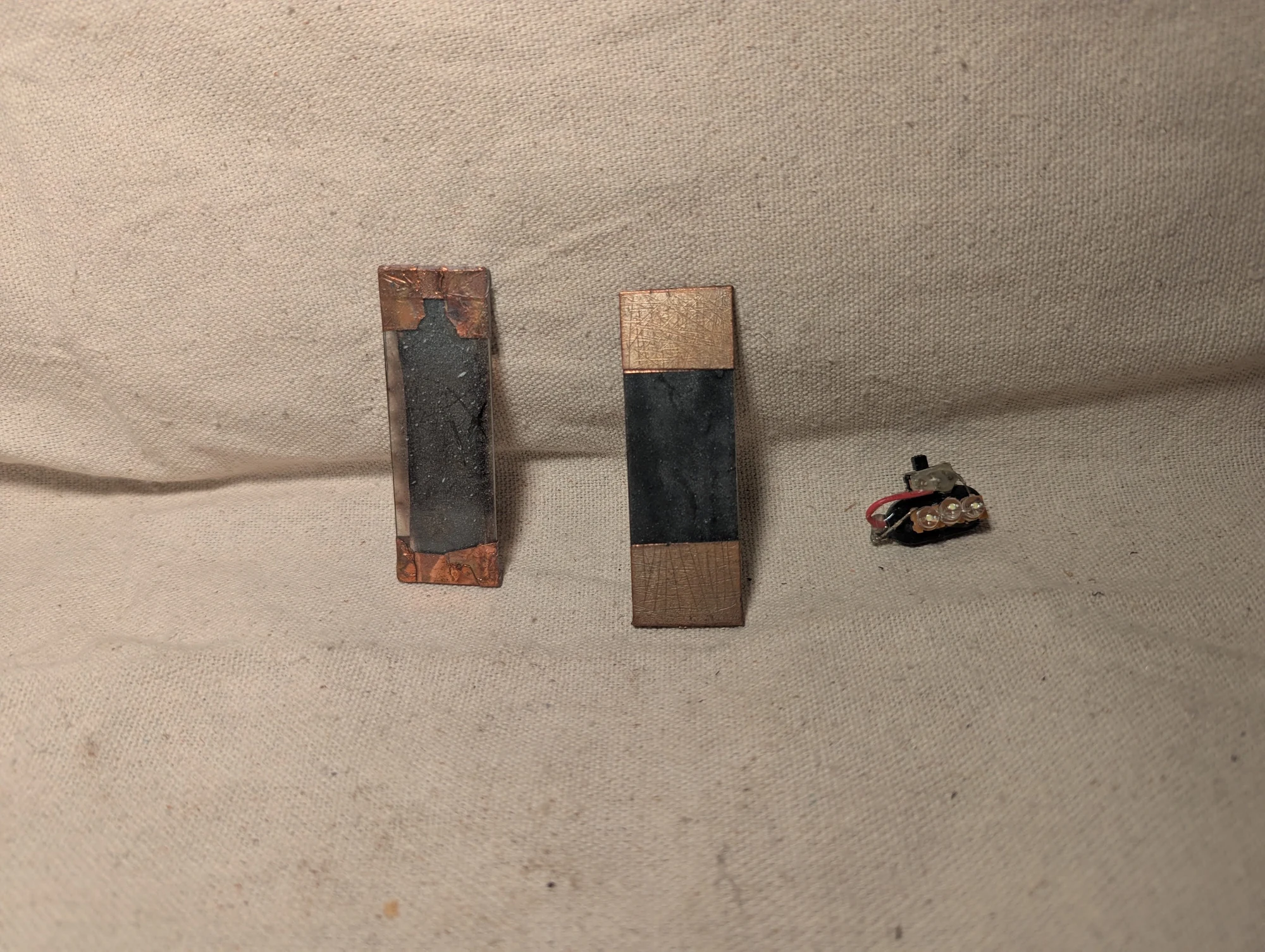
Experiments with thin heating elements made from fragile carbonized paper and graphite flakes. I was exploring these materials as lightweight, thin heaters.
Another view of the experimental carbon and graphite heating elements. The fragile materials were part of my exploration of thin heater designs.
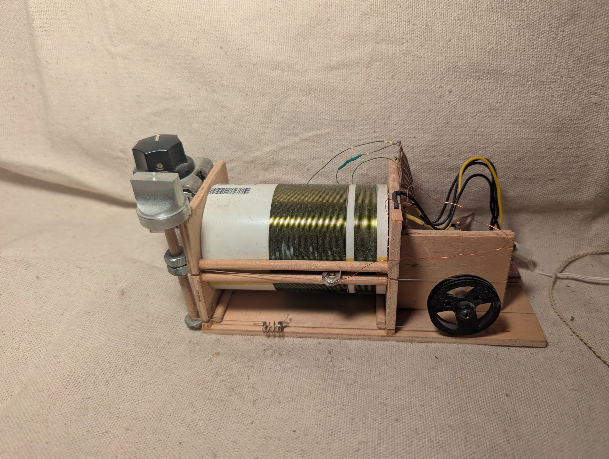
A crystal radio I built around 2013–2014 while staying in Niantic, Connecticut, during a power-plant internship. I made it with a single multi-tool and basic supplies from local stores. Working at a small table by the coast, with a view of the water, made this a particularly memorable project.
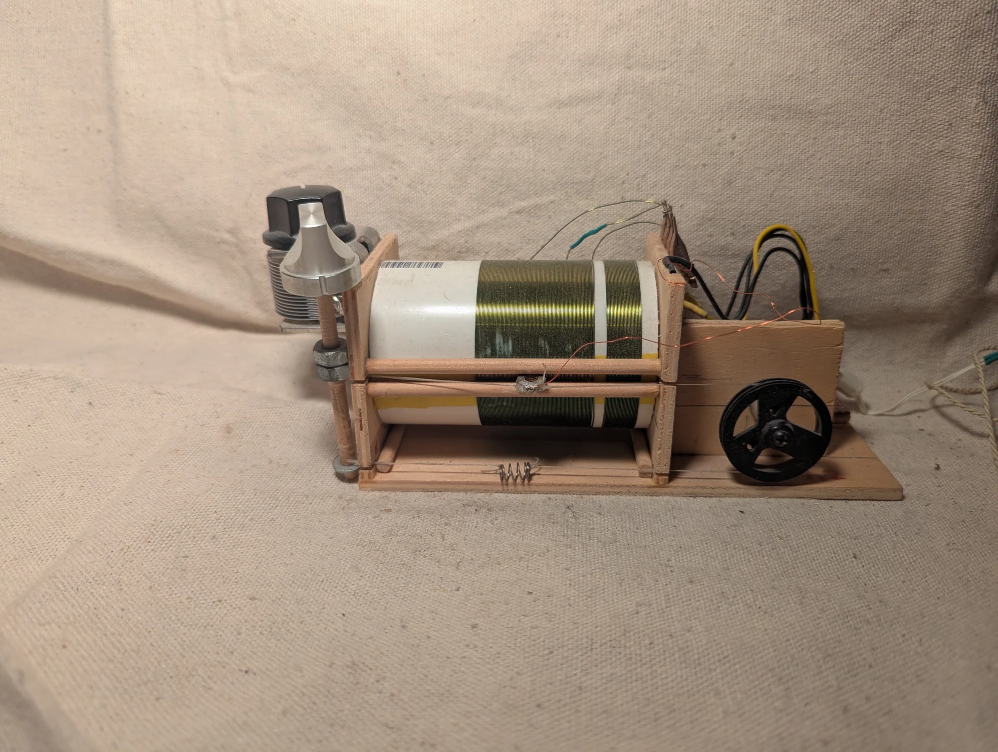
Another view of the crystal radio made with a multi-tool and locally purchased supplies during my power-plant internship.
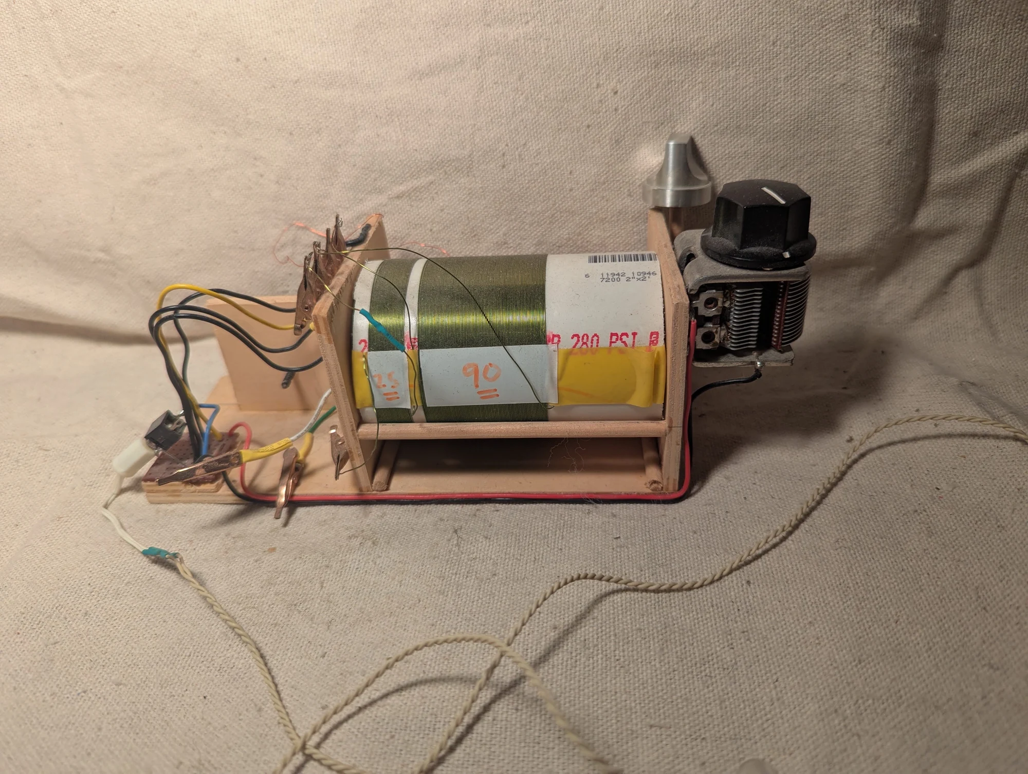
A different angle on the hand-built crystal radio, showing more of its frame, wiring, and components.
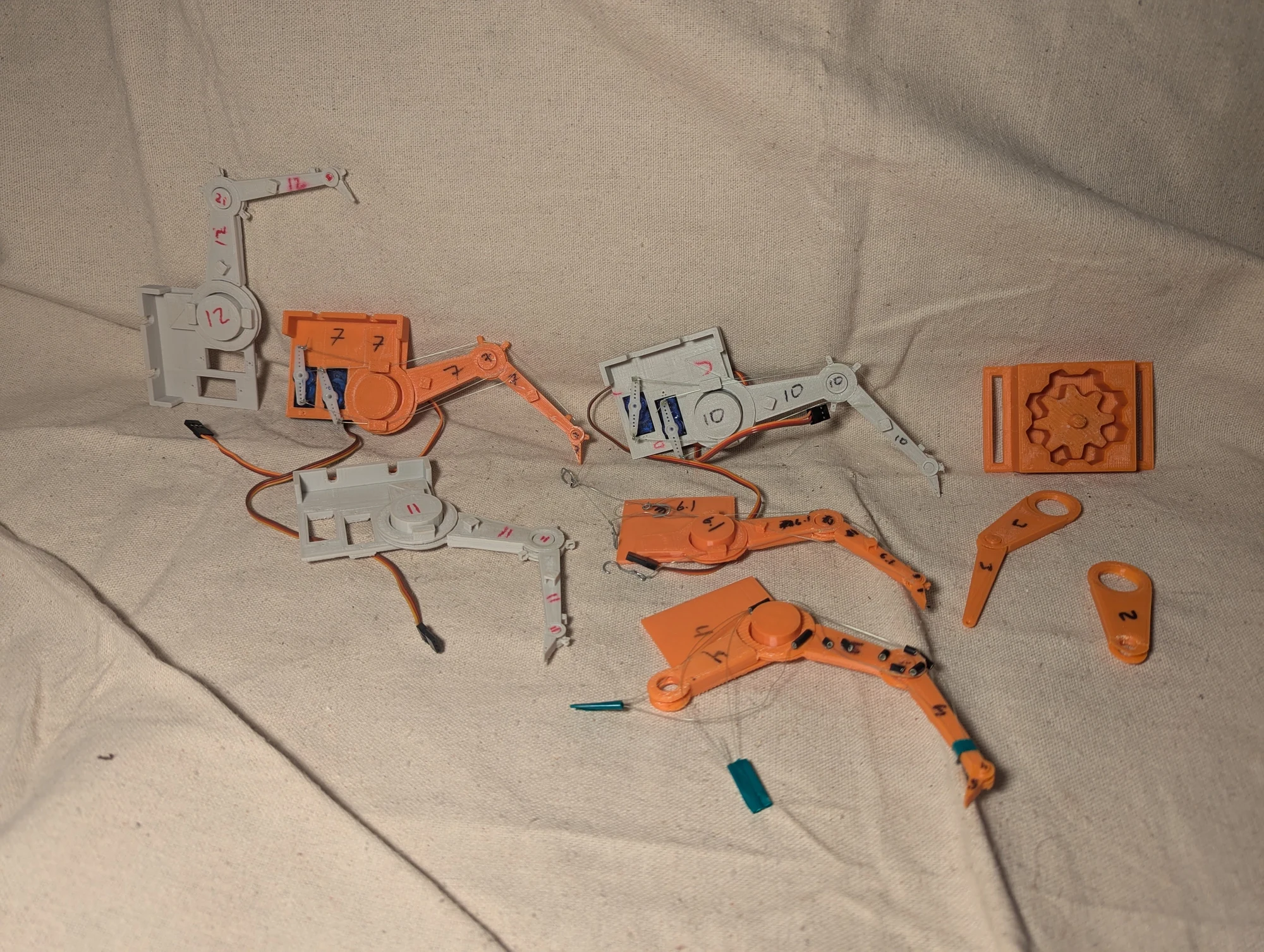
A collection of prototypes from my robotic crab-leg project, showing how the mechanism changed over many iterations. I also experimented with a wax-based mechanism intended to permit motion when the wax melted and hold a position when it solidified.
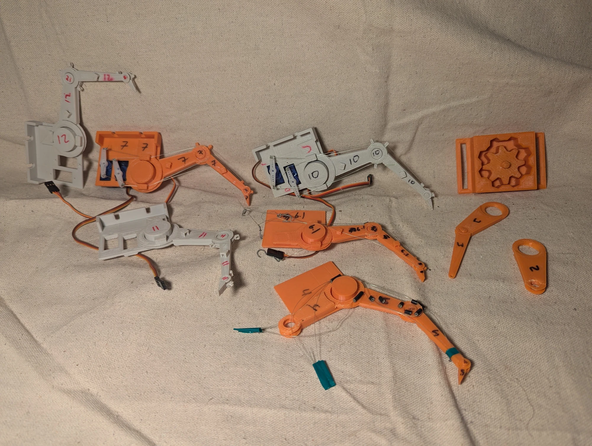
Another view of the collection of crab-leg mechanisms and related experiments. Making multiple versions let me explore different approaches to movement and joint control.
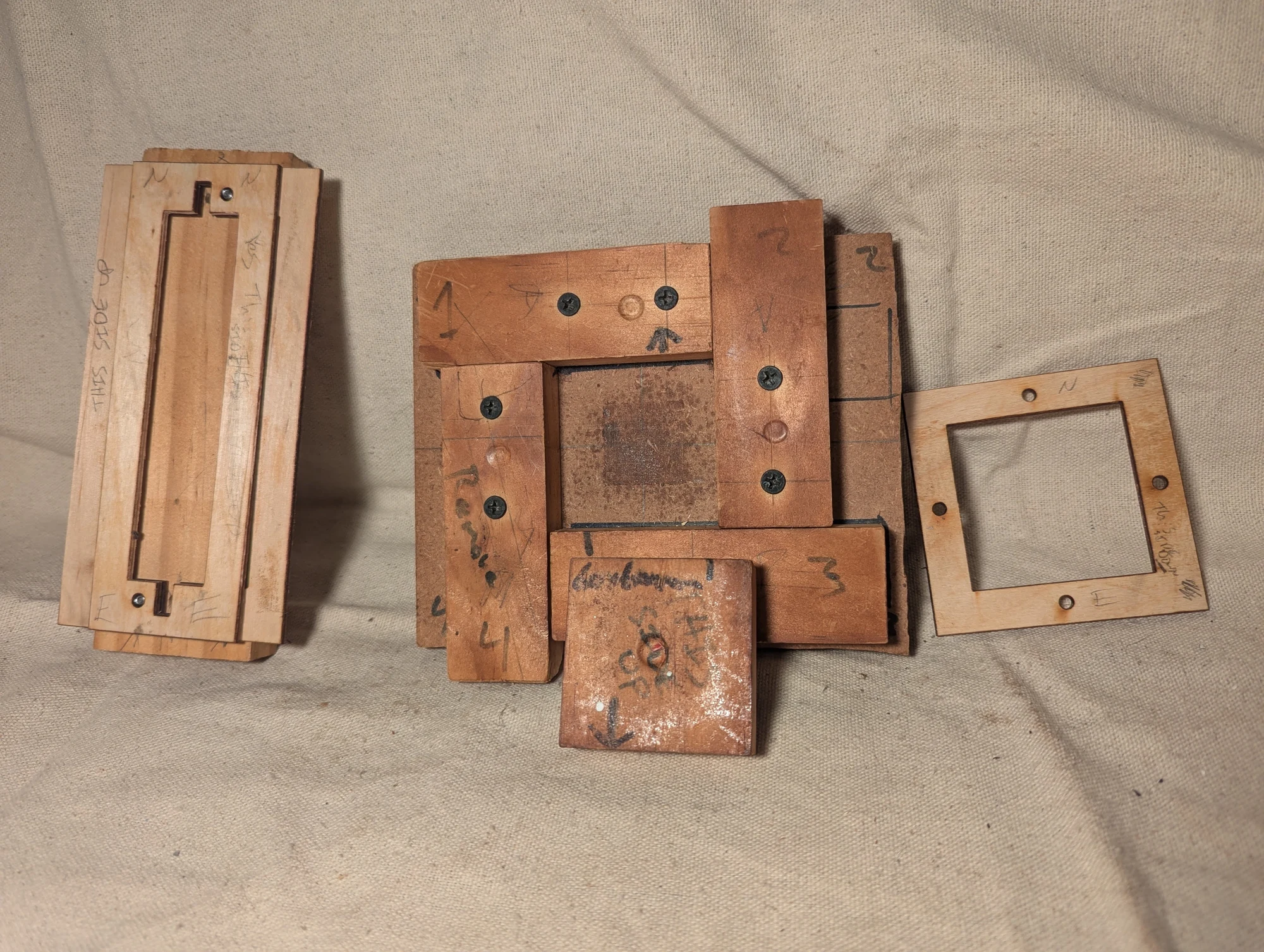
Jigs used to hold acrylic microfluidic layers together during bonding. After sanding and cleaning the pieces, I stacked them in a fixture, heated the assembly in an oven, and compressed the layers with a clamp. The square fixture was my main jig; the longer version accommodated elongated chips.
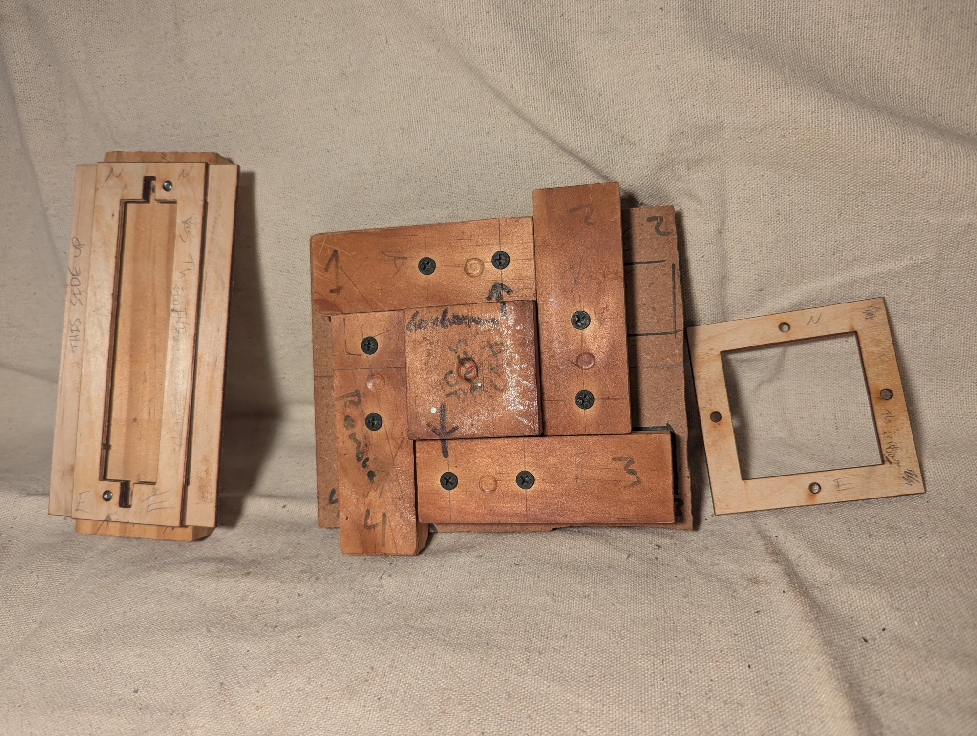
Another view of the fixtures used to align and compress heated acrylic layers. Different fixture shapes accommodated the square and elongated microfluidic devices.
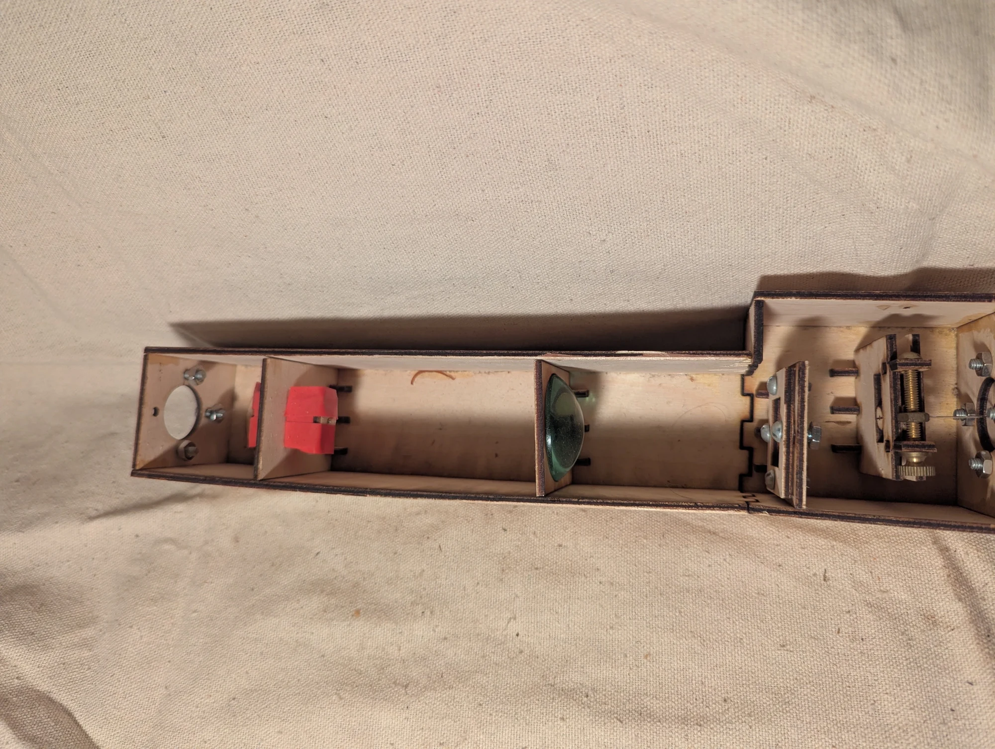
An optical prototype that used ultraviolet light to excite red, green, and blue fluorescent fibers. A lens and diffraction grating spread the resulting light by wavelength, and a screw-driven slider positioned a receiving fiber to collect a selected color. The goal was to change the output wavelength while retaining the information carried by changes in the incoming UV light.
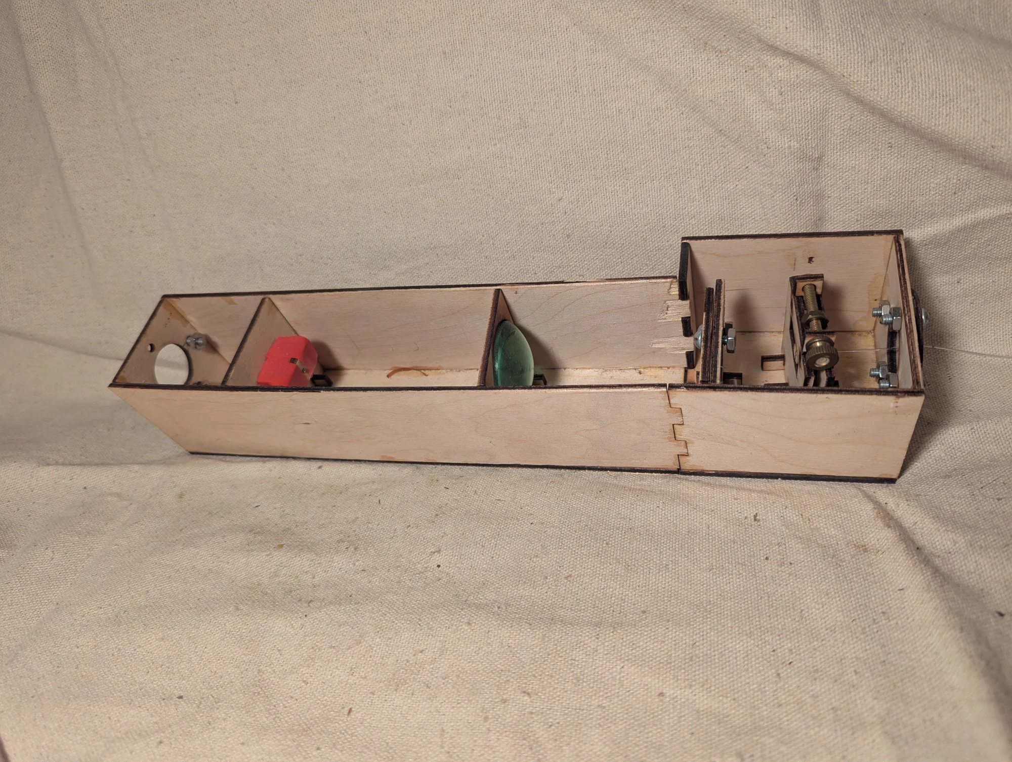
Another view of the optical bench. Fluorescent fibers converted ultraviolet excitation into visible light, and the adjustable receiving fiber collected a selected part of that light after it passed through the optics. The selected wavelength could be changed manually.
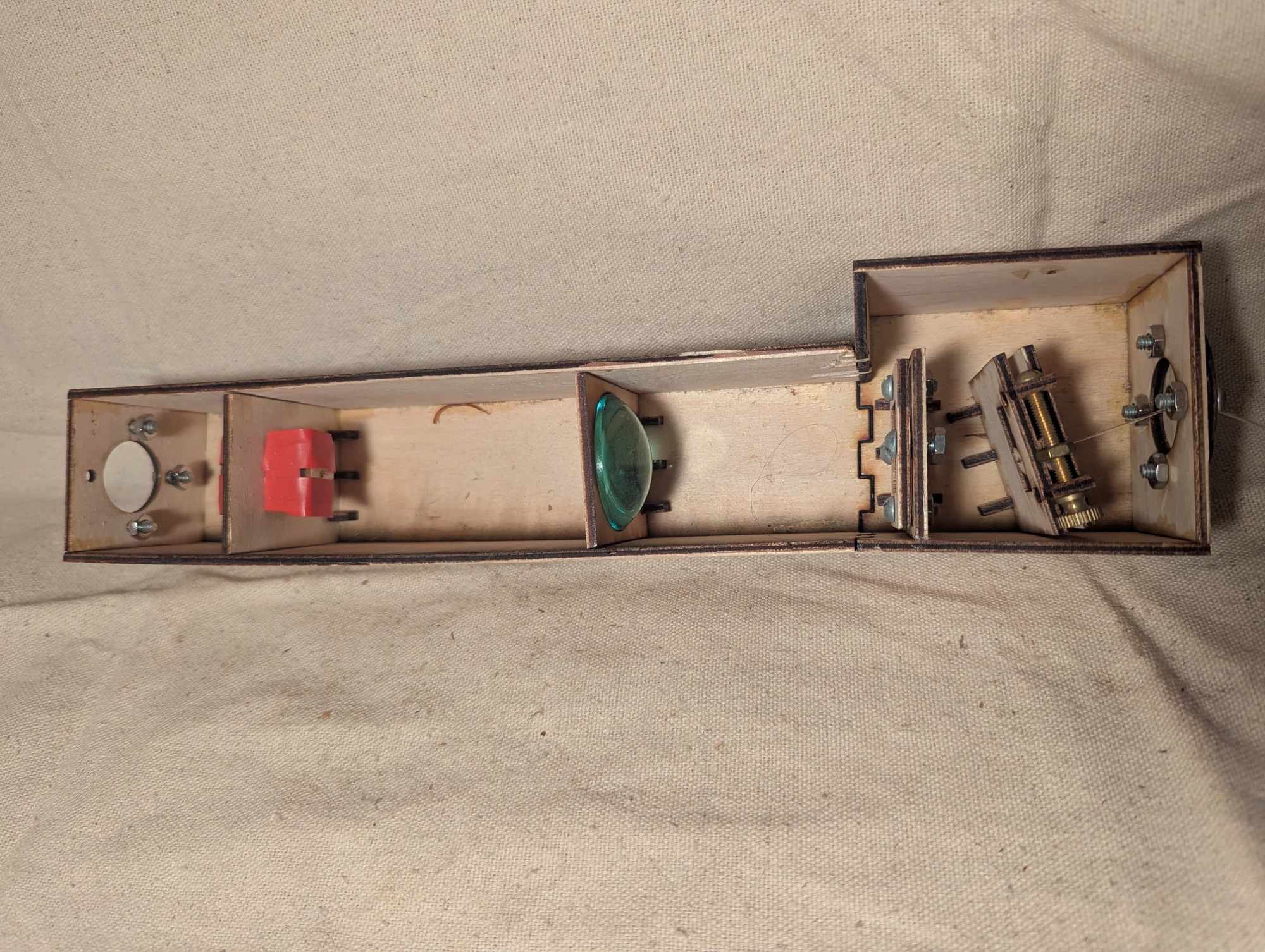
The bolt-and-nut adjustment moved the receiving fiber across the separated light. Changing the slider position selected a different wavelength range from the fluorescent source.
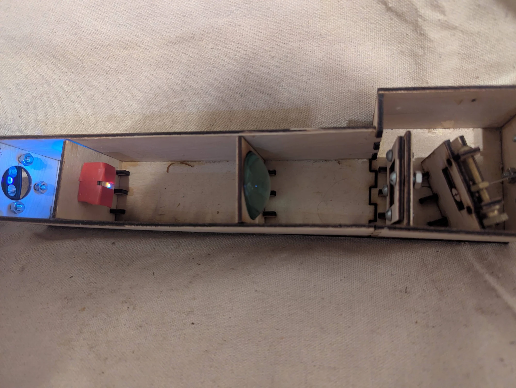
The fluorescent source illuminated with ultraviolet light. The intended application was to carry an optical signal into a different wavelength range, with the output color chosen by moving the receiving fiber. This view shows the mixed-color source and the manually adjustable optical assembly.
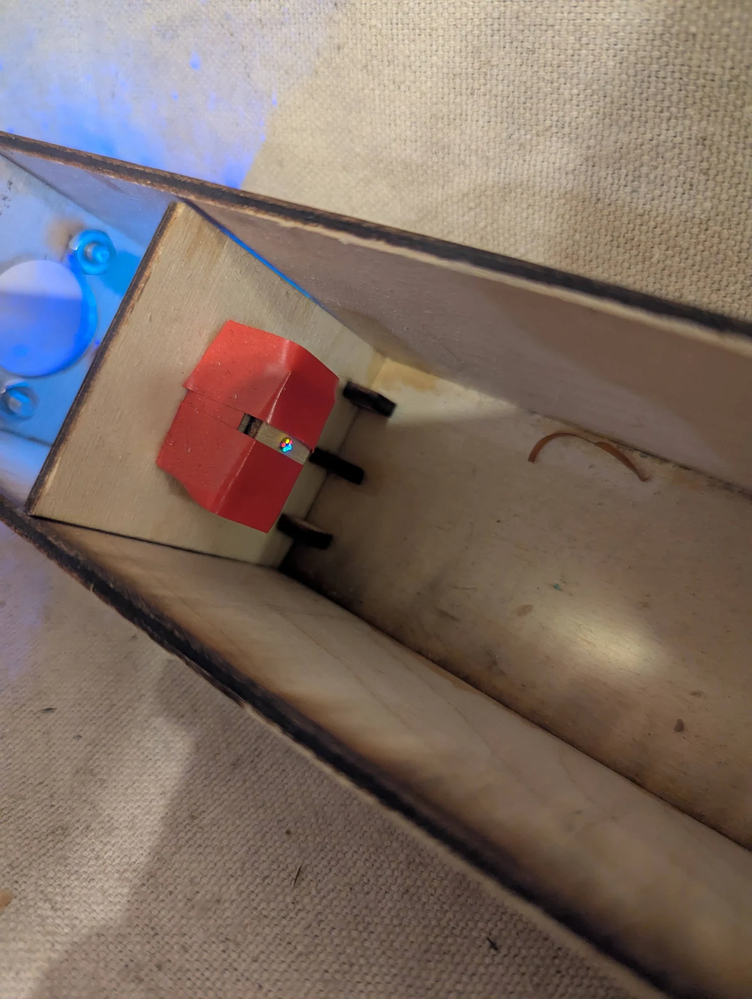
A close view of the red, green, and blue fluorescent fibers used as a roughly white, mixed-color light source. I recall power consumption being a reason for using UV-excited fluorescence instead of a tungsten lamp.
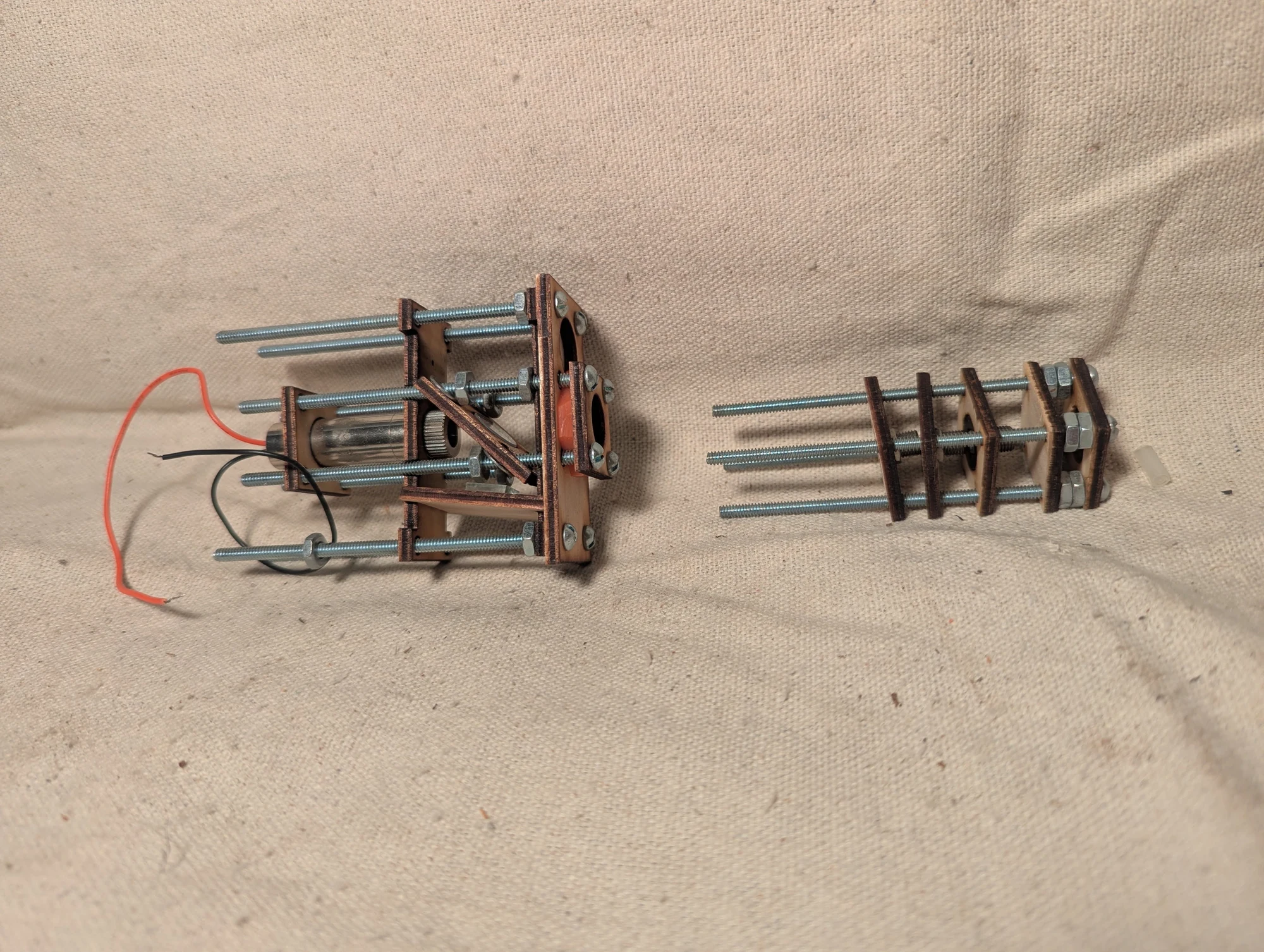
A compact acoustic-sensor prototype based on a Michelson interferometer. A beam splitter sent light along two paths, one to a reference mirror and one to a mirror on a flexible silicone membrane. The returning beams were intended to form bright and dark interference bands. Sound moving the membrane would shift those bands, providing a possible way to detect its motion. The prototype still needed further refinement.
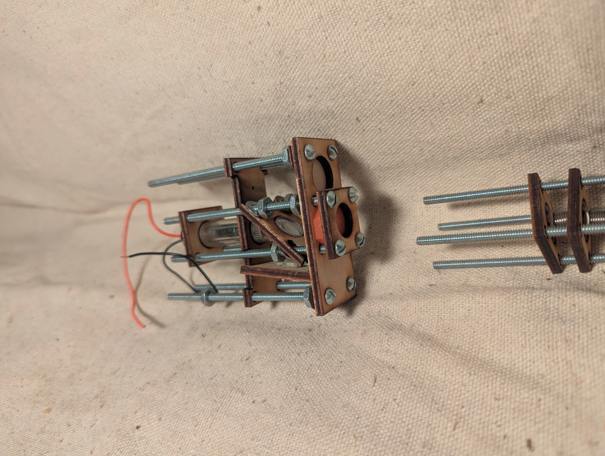
Another view of the acoustic interferometer. A first-surface mirror was carried by a thick silicone membrane and held in place using magnets on opposite sides. The aim was for small sound-driven movements of that mirror to change the interference pattern when its light recombined with the reference beam.
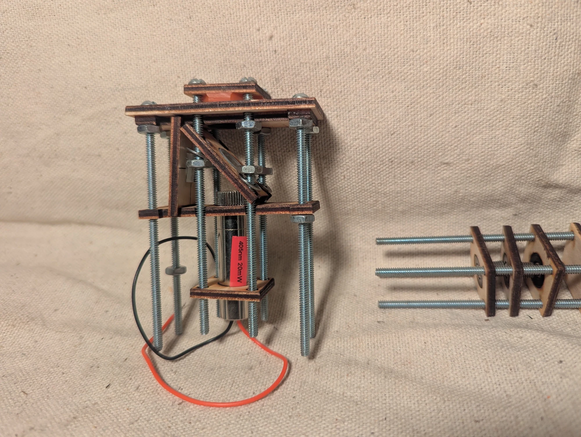
A further view of the acoustic interferometer. A light detector behind a small hole in the viewing plate was intended to sense alternating bright and dark bands as the interference pattern moved. The idea was to turn those brightness changes into an electrical signal related to membrane motion; the detector type and measured performance are unconfirmed.
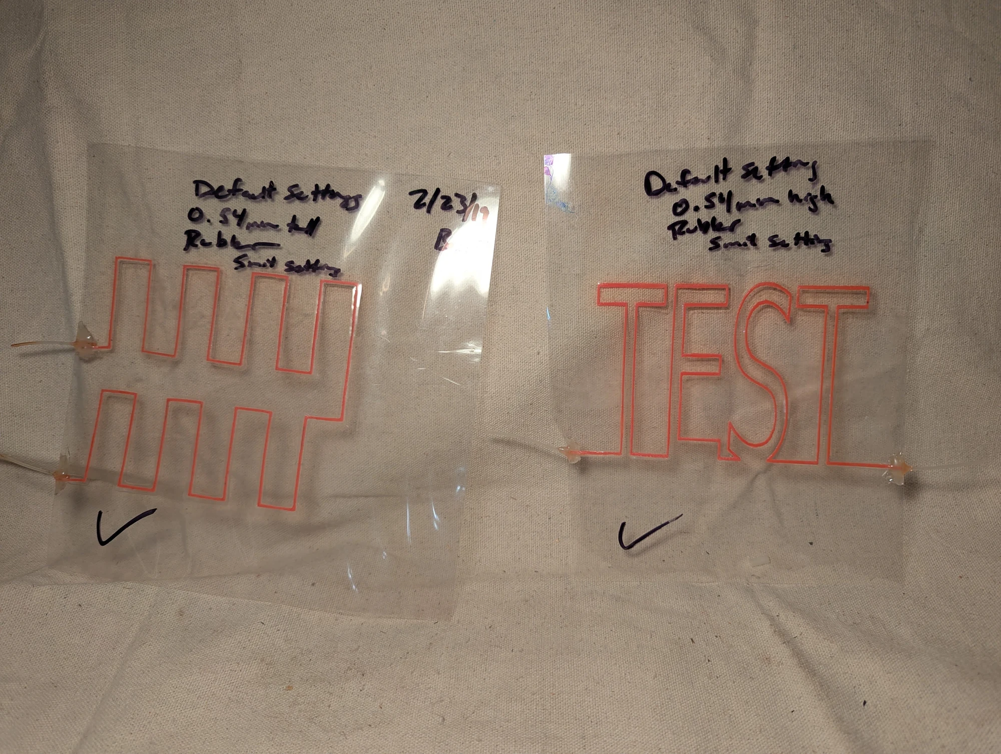
An experiment from around 2019 using a single-layer 3D-printed pattern between laminated sheets. The printed material acted as a spacer, holding the sheets slightly apart to create a path for air or liquid. I tried winding, serpentine patterns as possible heat-exchanger channels; the notes on these samples record the early tests.
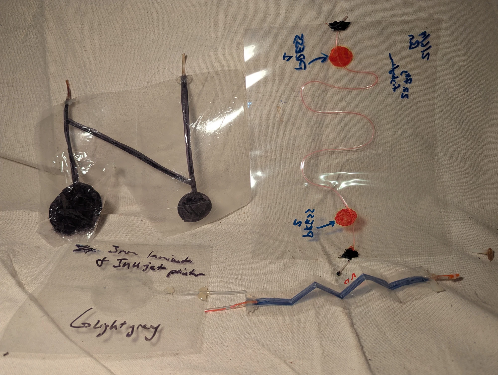
Samples exploring two ways to form channels: a filament could hold the sheets apart, or a marker line could prevent them bonding along a drawn path. The collection also includes a distillation concept, intended to evaporate liquid in one chamber and collect condensate in another, and flexible structures that expanded when filled with air.
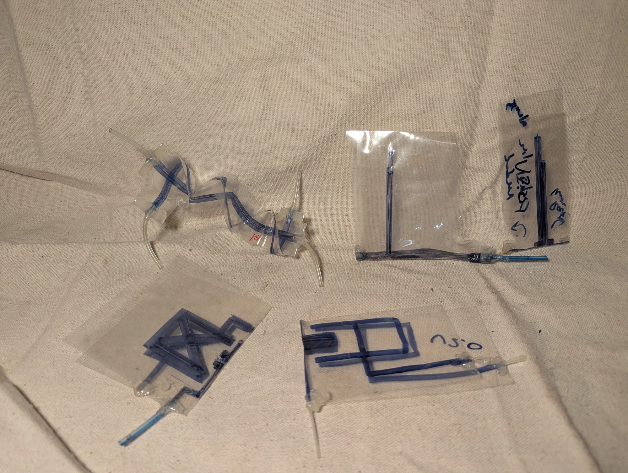
Laminated patterns designed to change shape when pressurized. Accordion-like folds could collapse when empty and expand when inflated. I tried different layouts as possible pneumatic muscles and joints, exploring motion produced by air pressure.
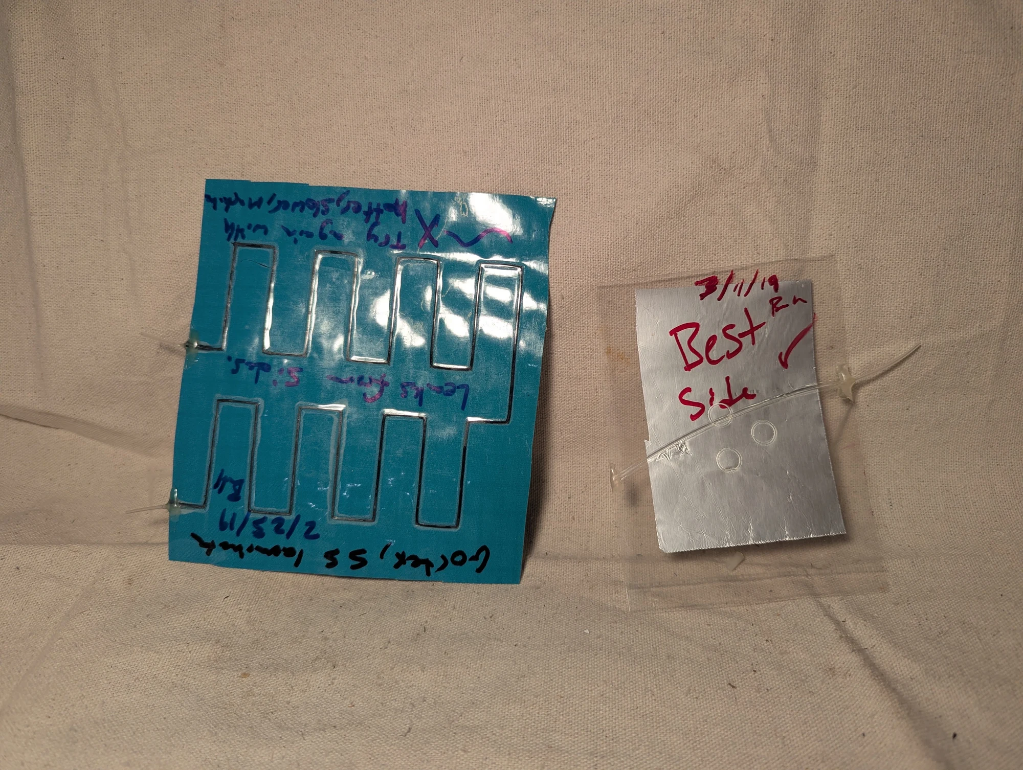
Experiments toward a thin, flexible panel that could carry water to move heat in a wearable garment. I compared laminated sheets with samples incorporating foil and Gore-Tex, aiming for comfort and a useful fluid path. In these trials, the added materials did not bond as reliably as the laminated sheets bonded to one another.
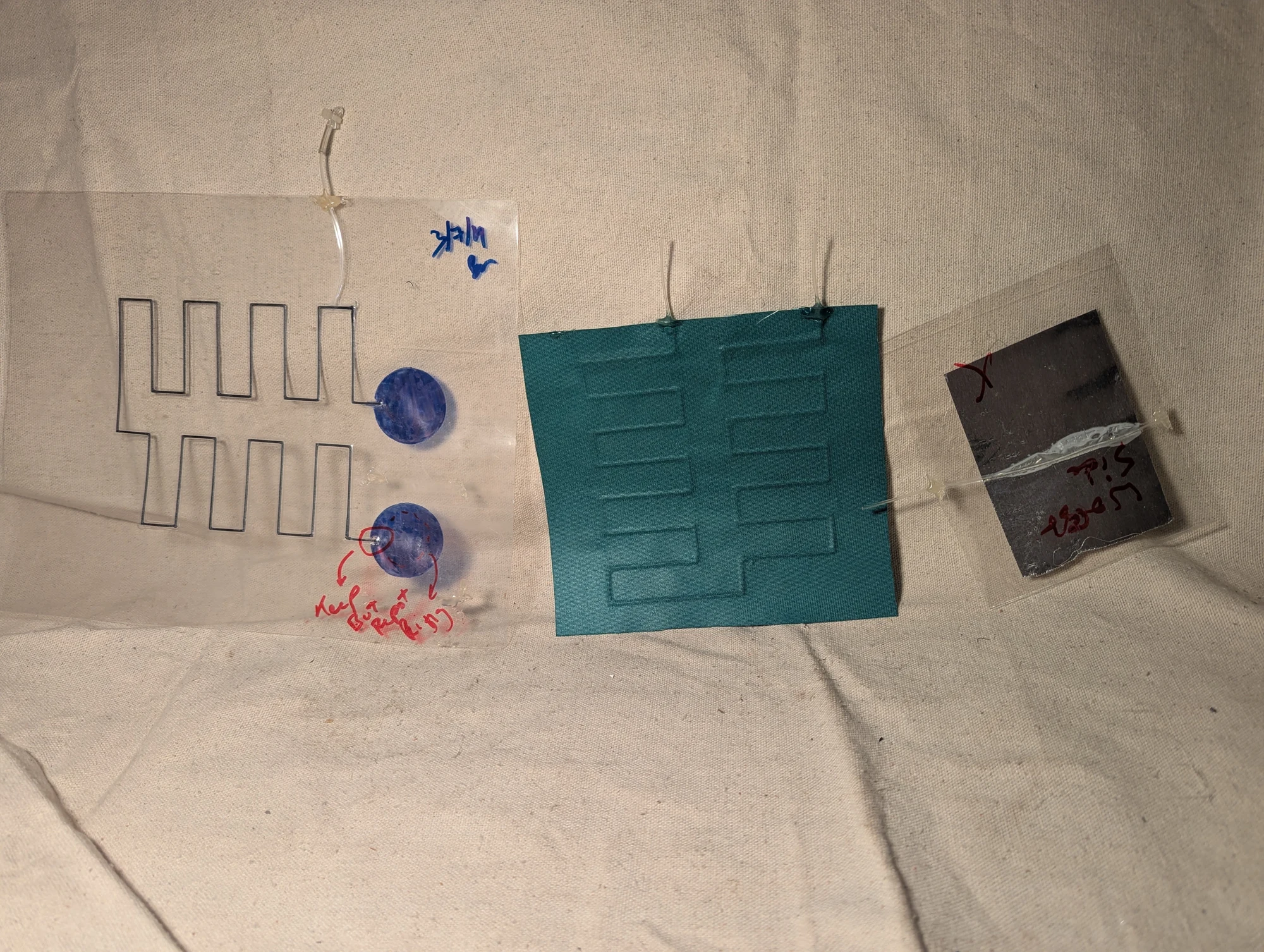
A collection of channel patterns and material samples from the wearable-cooling experiments. I was comparing how thin sheets could enclose a water path while remaining flexible and holding together under pressure.
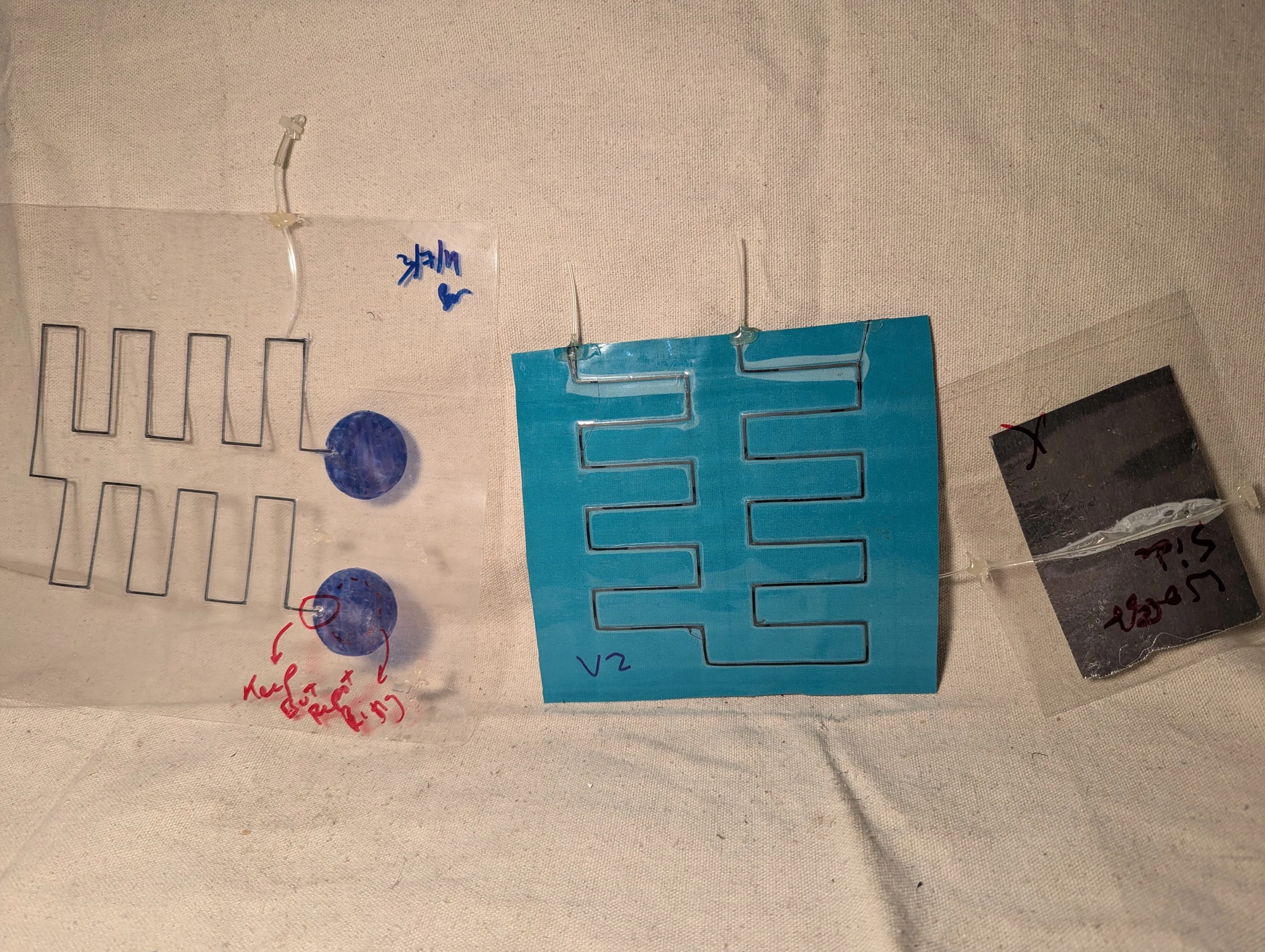
Another view of the flexible channel samples. These were exploratory tests of construction methods and bonding for a potential wearable cooling panel.
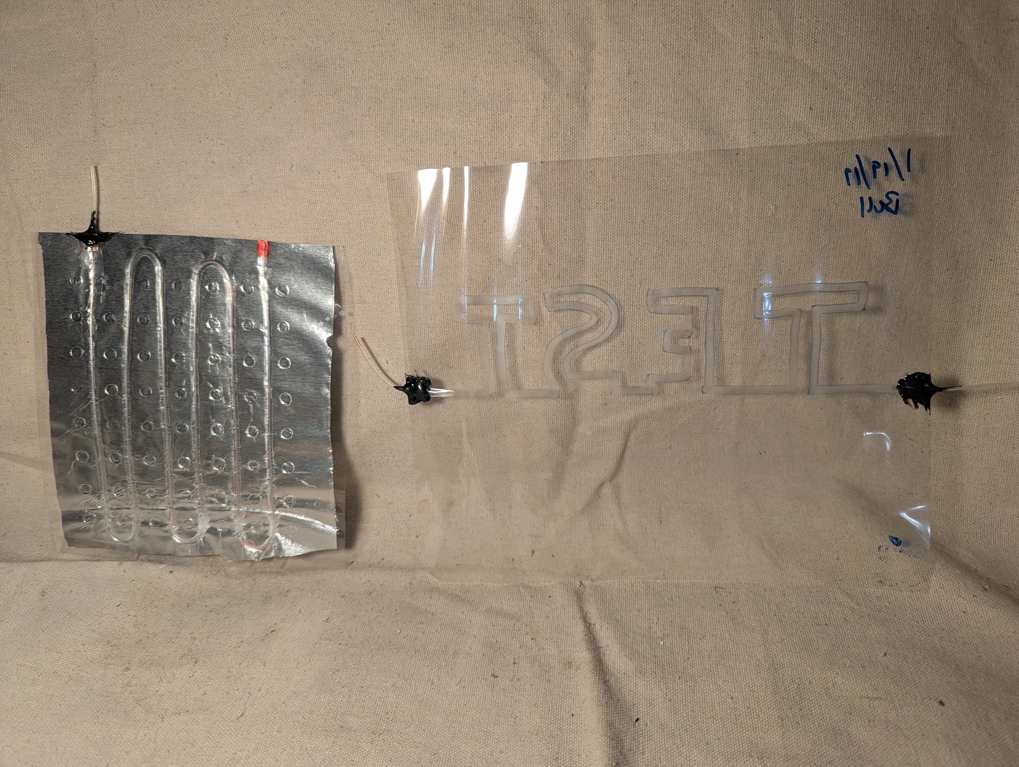
A thin heat-exchanger prototype incorporating foil. I remember it working reasonably well as an early experiment, but I did not pursue this version further and no longer recall why.
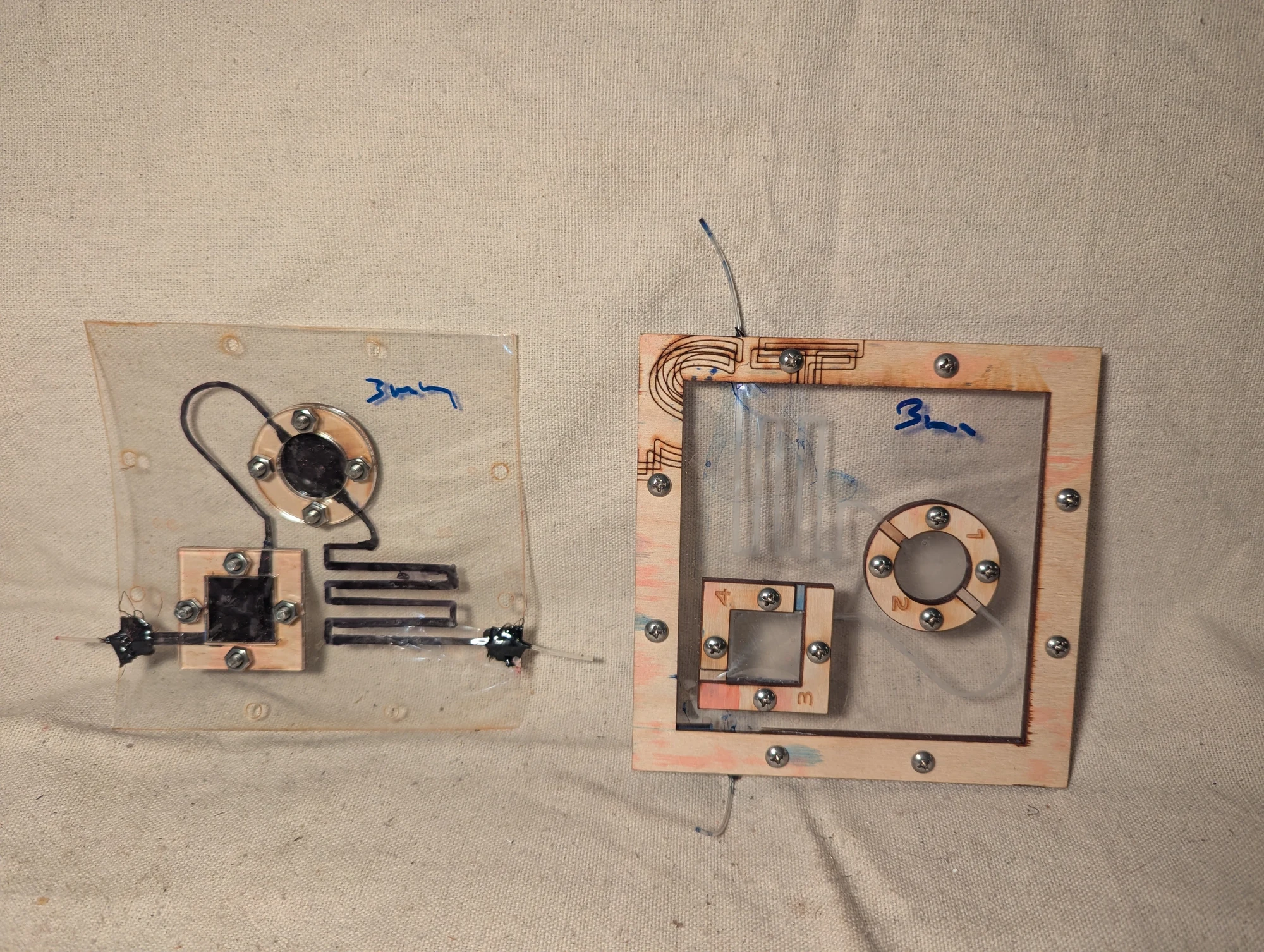
Larger laminated chambers were more prone to the layers separating under pressure. I added bolted wooden supports around the chambers to help retain their shape and keep the sheets pressed together. This was an experiment in reinforcing the fluid structures.
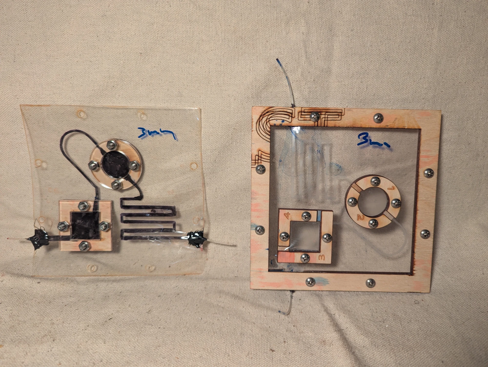
Another view of the laminated fluid chambers and their wooden supports. The supports were intended to reduce separation of the bonded sheets as the internal pressure increased.
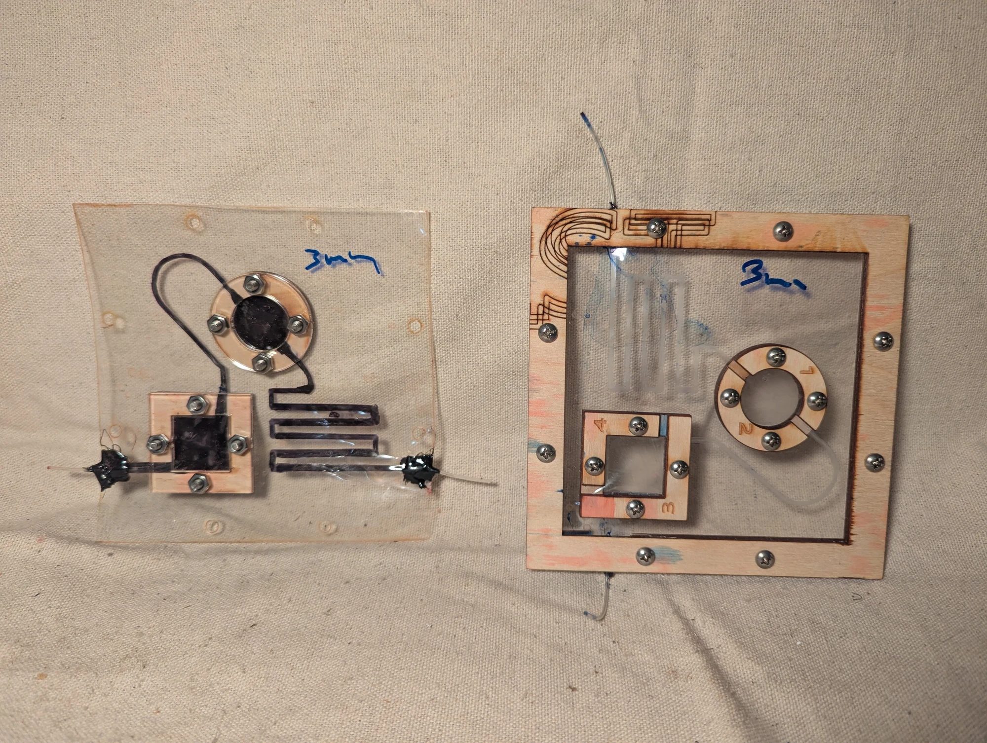
A further view of the reinforcement experiment, showing the supports used to hold the laminated chambers together.
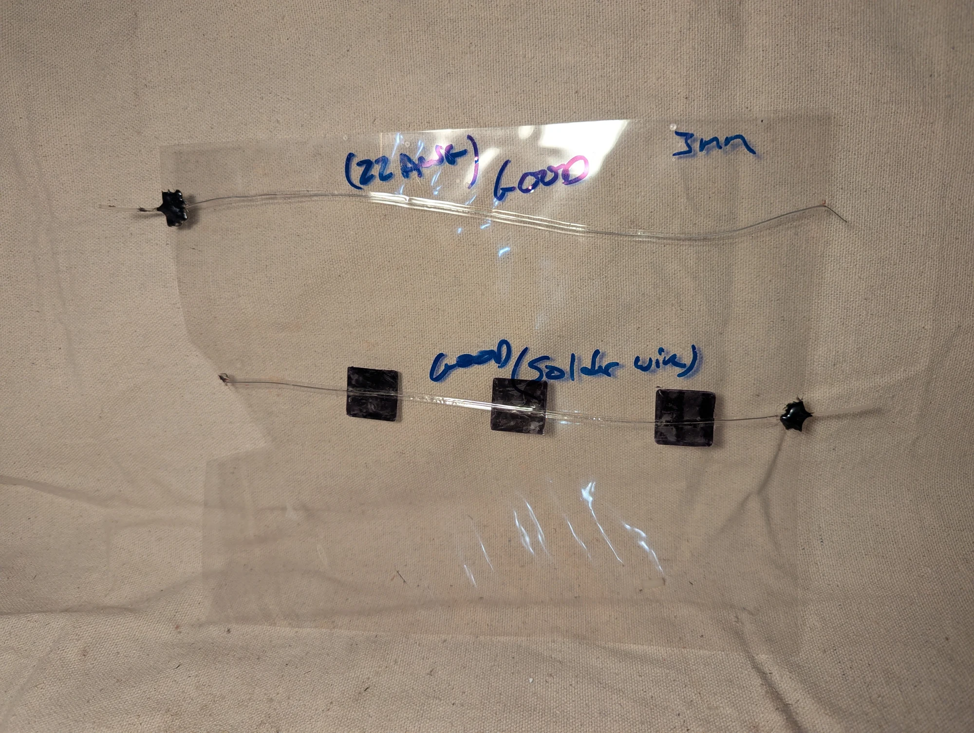
Fluid-channel experiments with fishing line sandwiched between laminated sheets. The line held the sheets apart along its path, leaving a small passage for air or liquid.
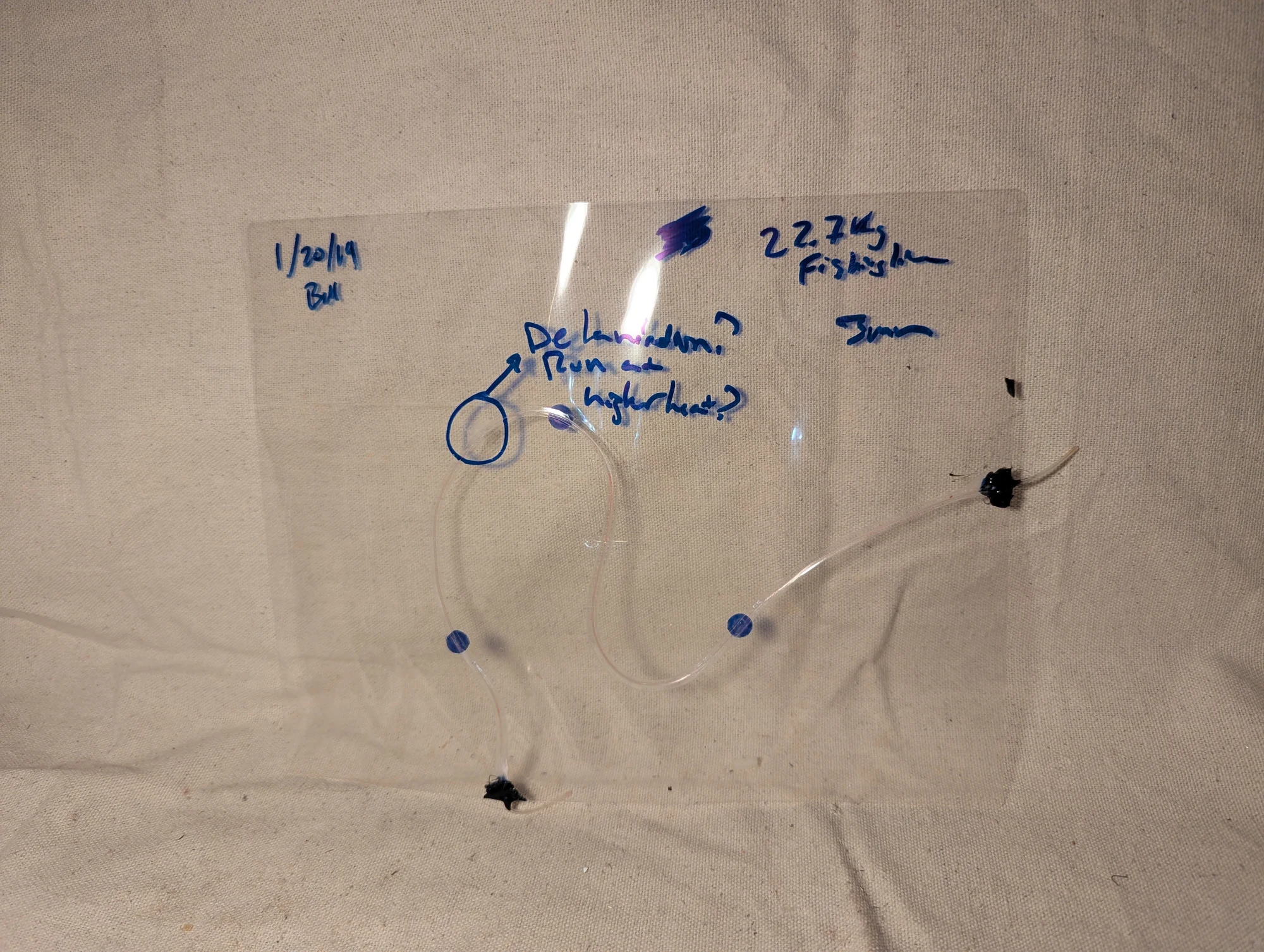
Further experiments with patterns and connections in laminated sheets. These samples explored different ways to form and connect small fluid passages.
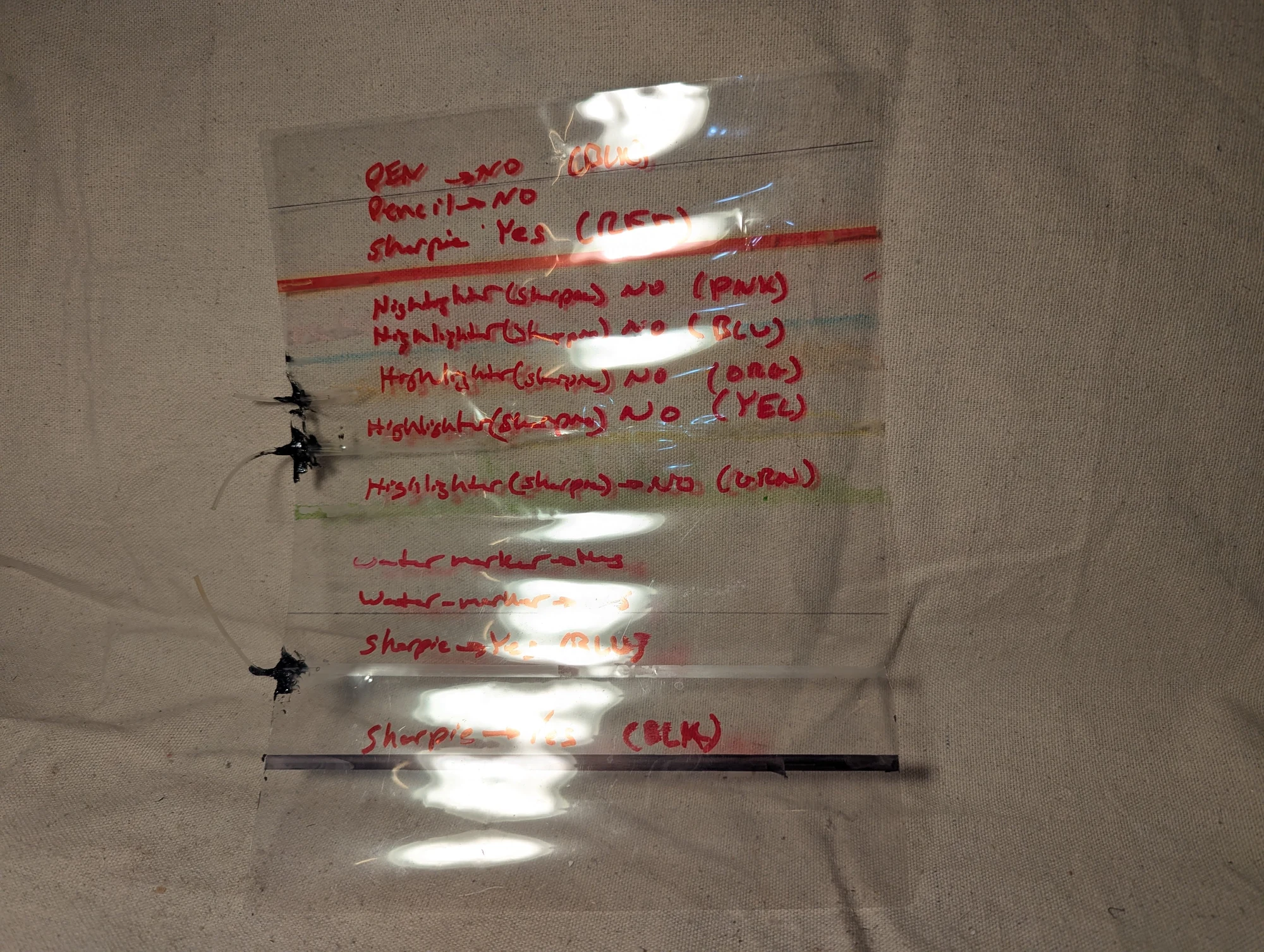
Test samples with handwritten notes comparing different inks and filament materials. In my trials, Sharpie worked best for drawn channels because the marked areas resisted bonding when the sheets were laminated together.
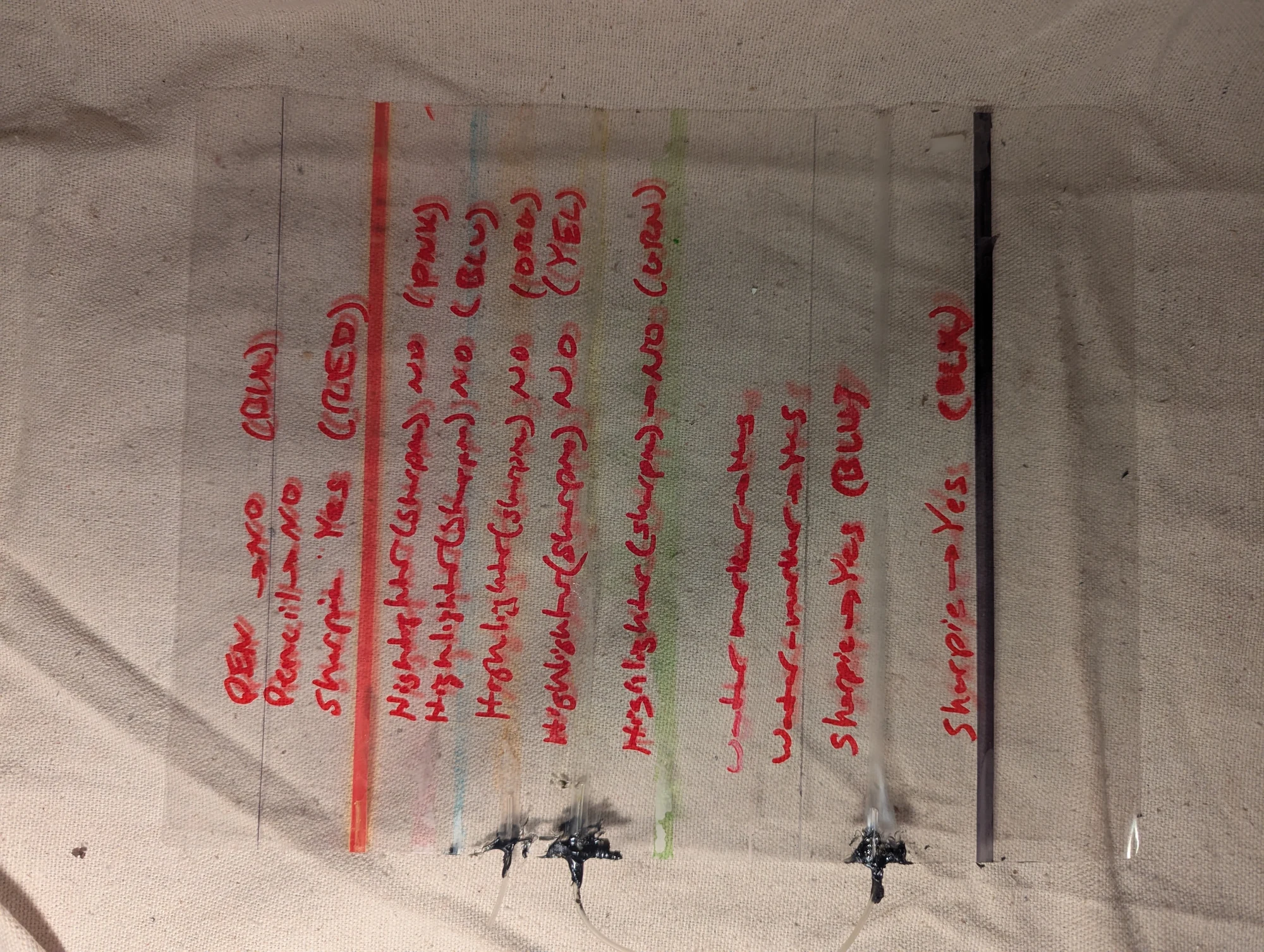
Another view of the notes and samples from the marker-and-filament comparison. These tests helped me choose materials for making fluid paths within laminated sheets.
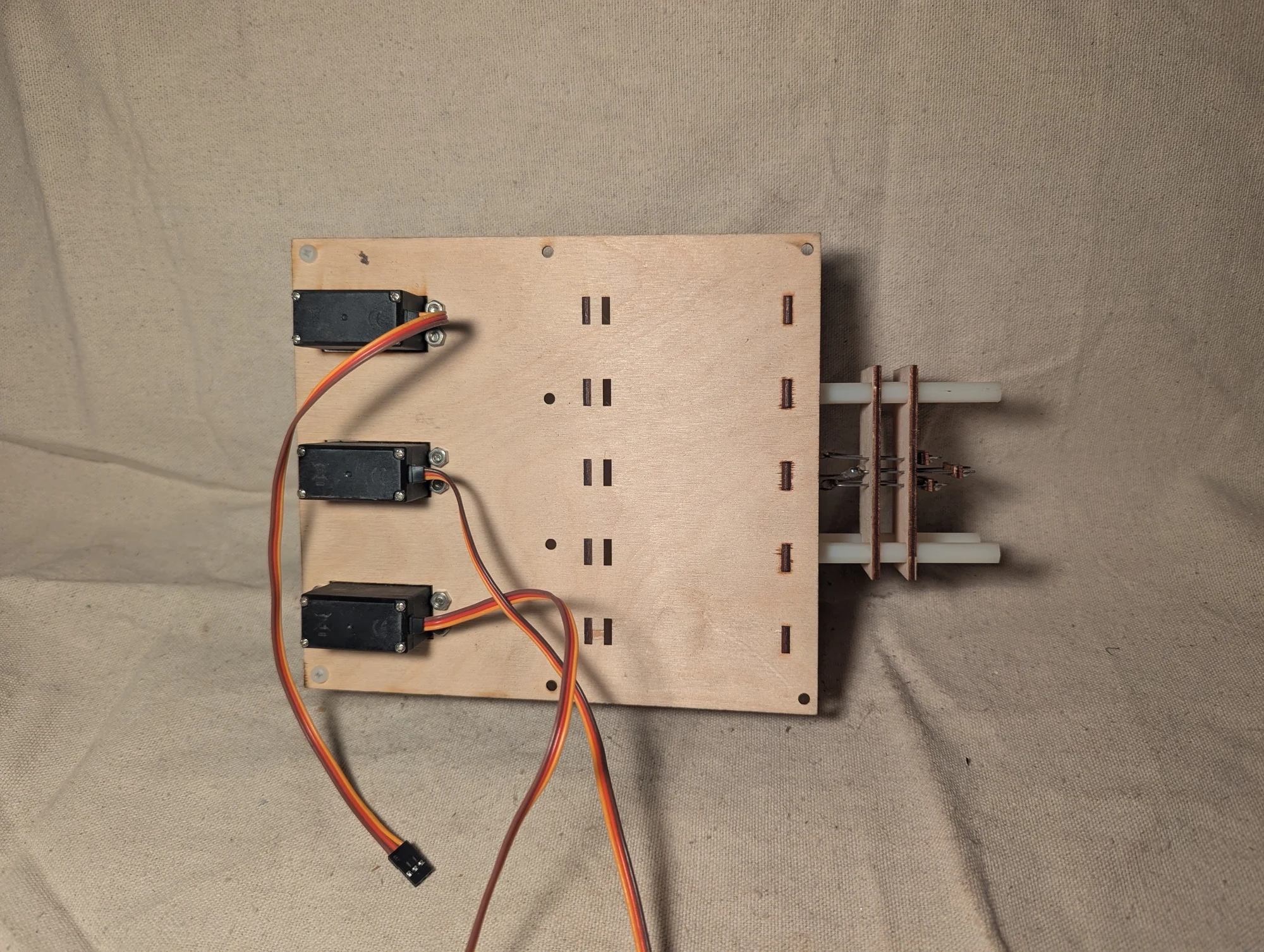
A prototype machine designed to crimp flexible heat-shrink tubing for an earlier materials experiment. I wanted to automate a repeated fabrication step, but I do not recall getting the mechanism working successfully. I later dismantled it to reuse the servos.
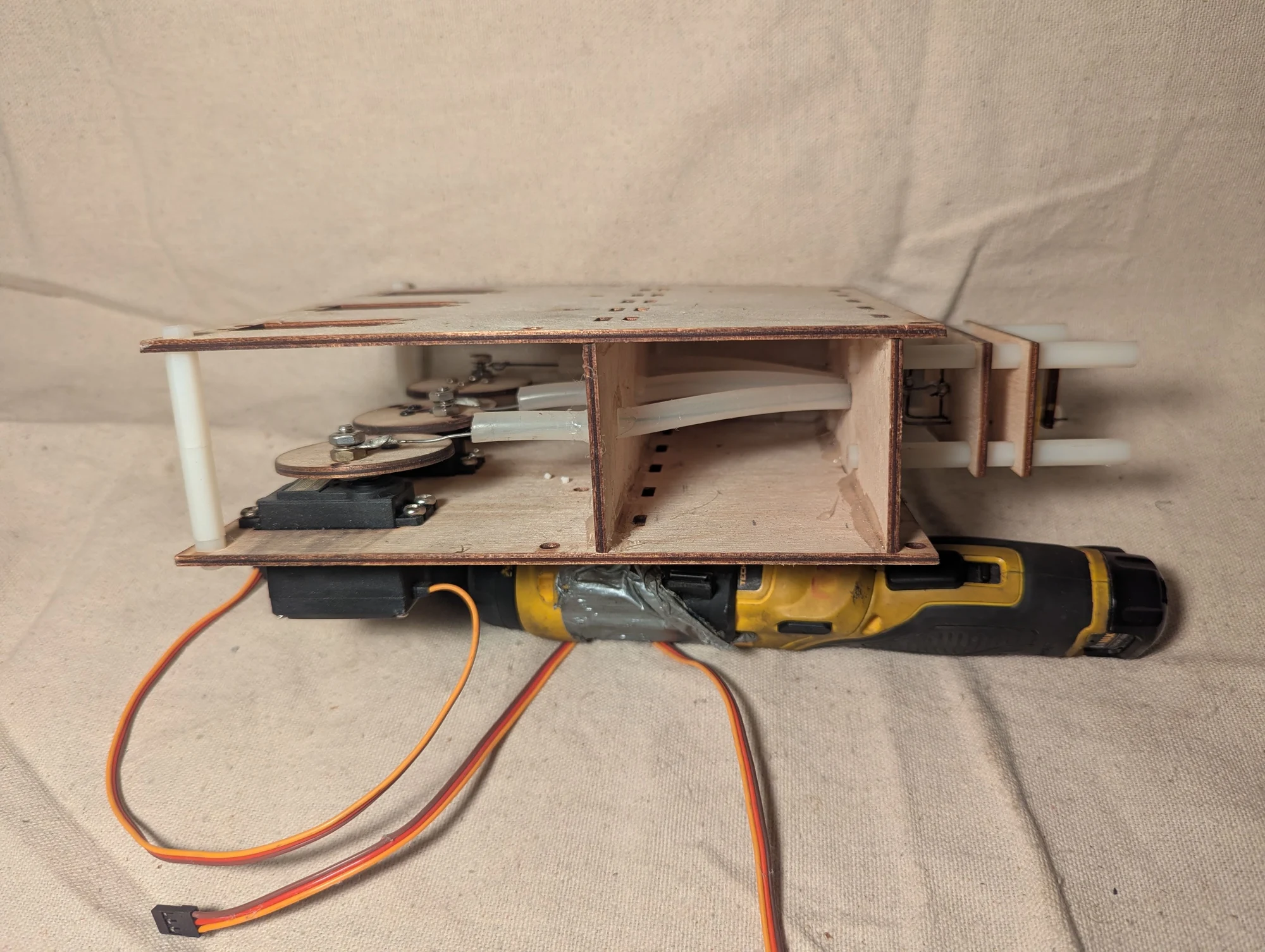
A side view of the experimental tubing-crimping machine, showing its frame and moving mechanism. The project focused on exploring repeatable mechanical fabrication.
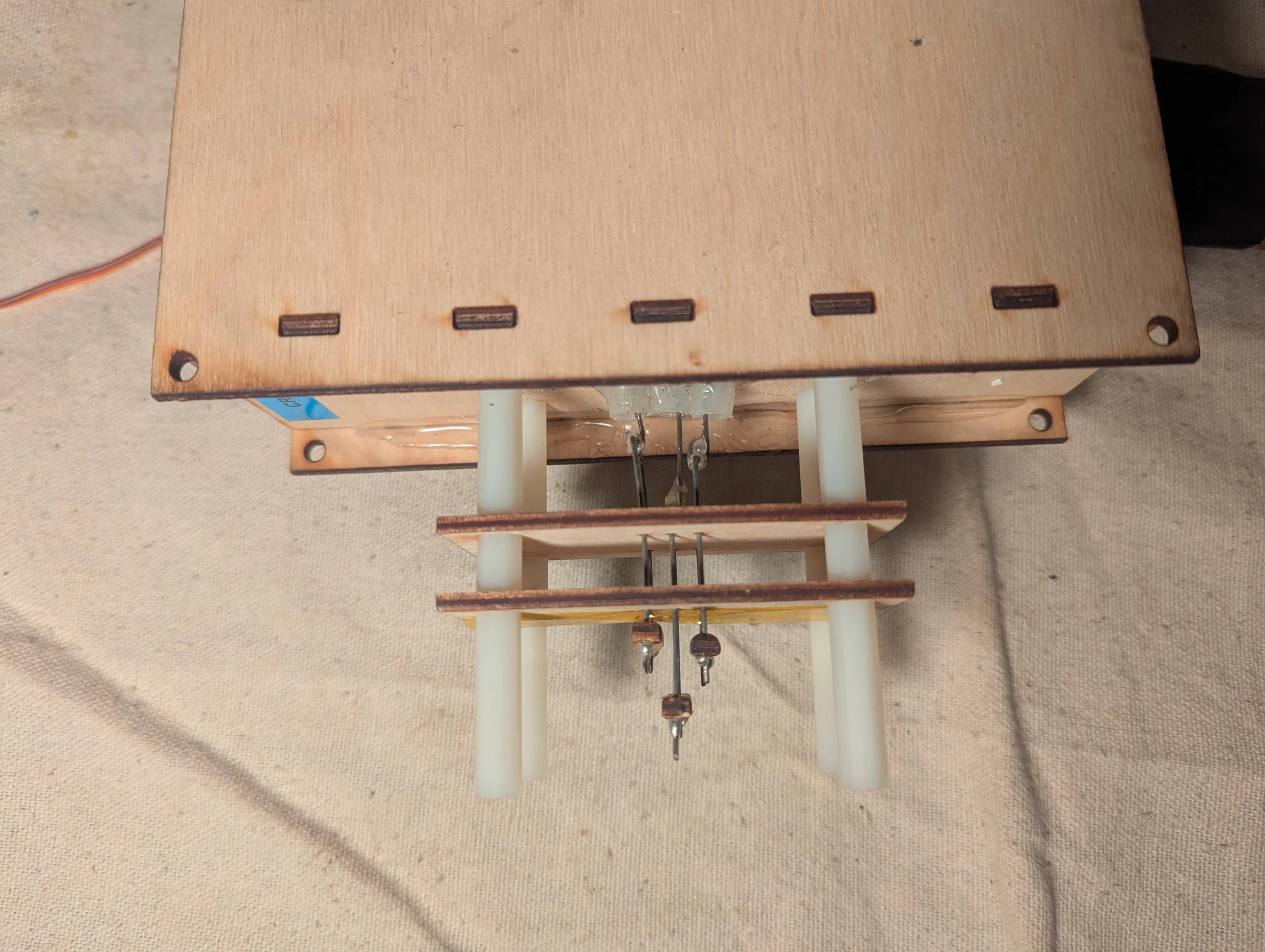
Another angle on the tubing-crimping prototype. It was designed as an experiment in automating a repetitive assembly operation.
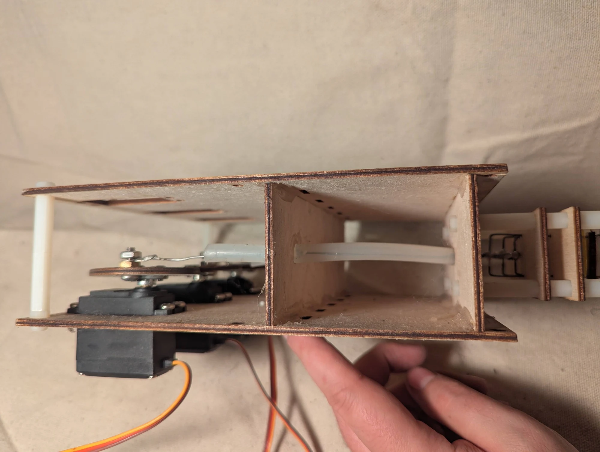
A further view of the frame and mechanism of the experimental crimping machine. The project explored batch fabrication through a repeated mechanical operation.
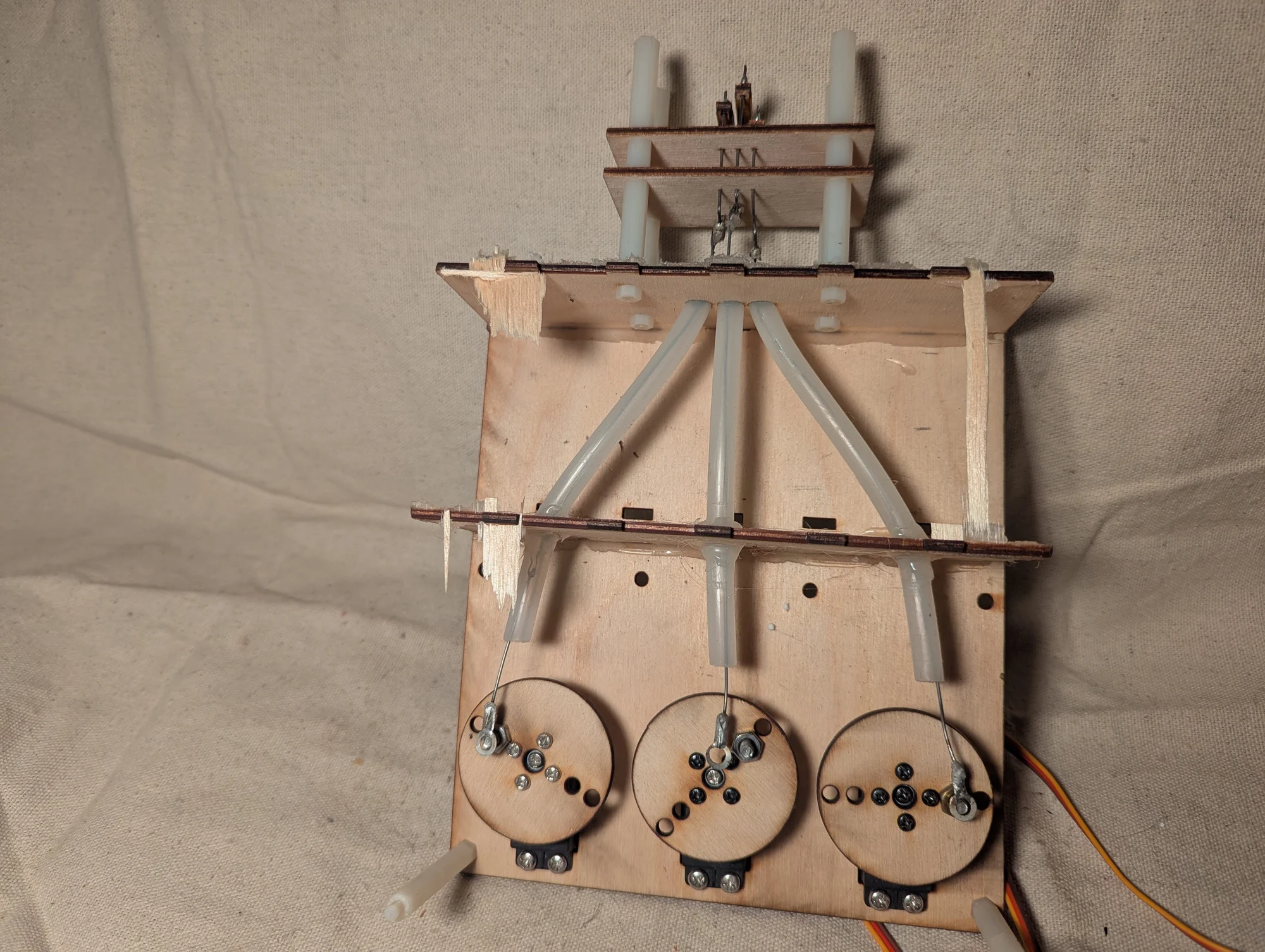
An end view of the experimental crimping machine. Its purpose was to automate a repetitive fabrication step; successful operation is unconfirmed. I eventually took the assembly apart and salvaged its servos for other work.
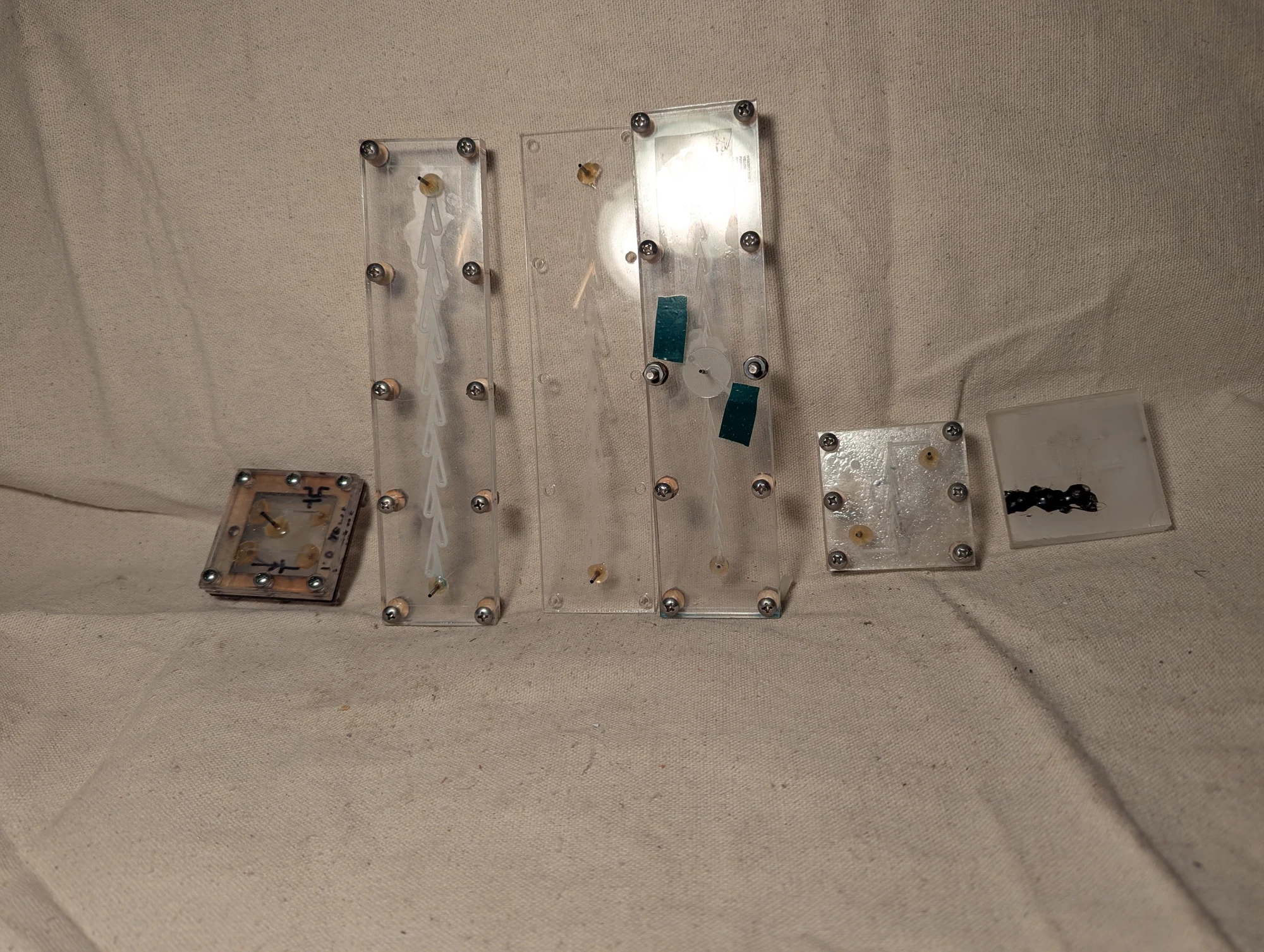
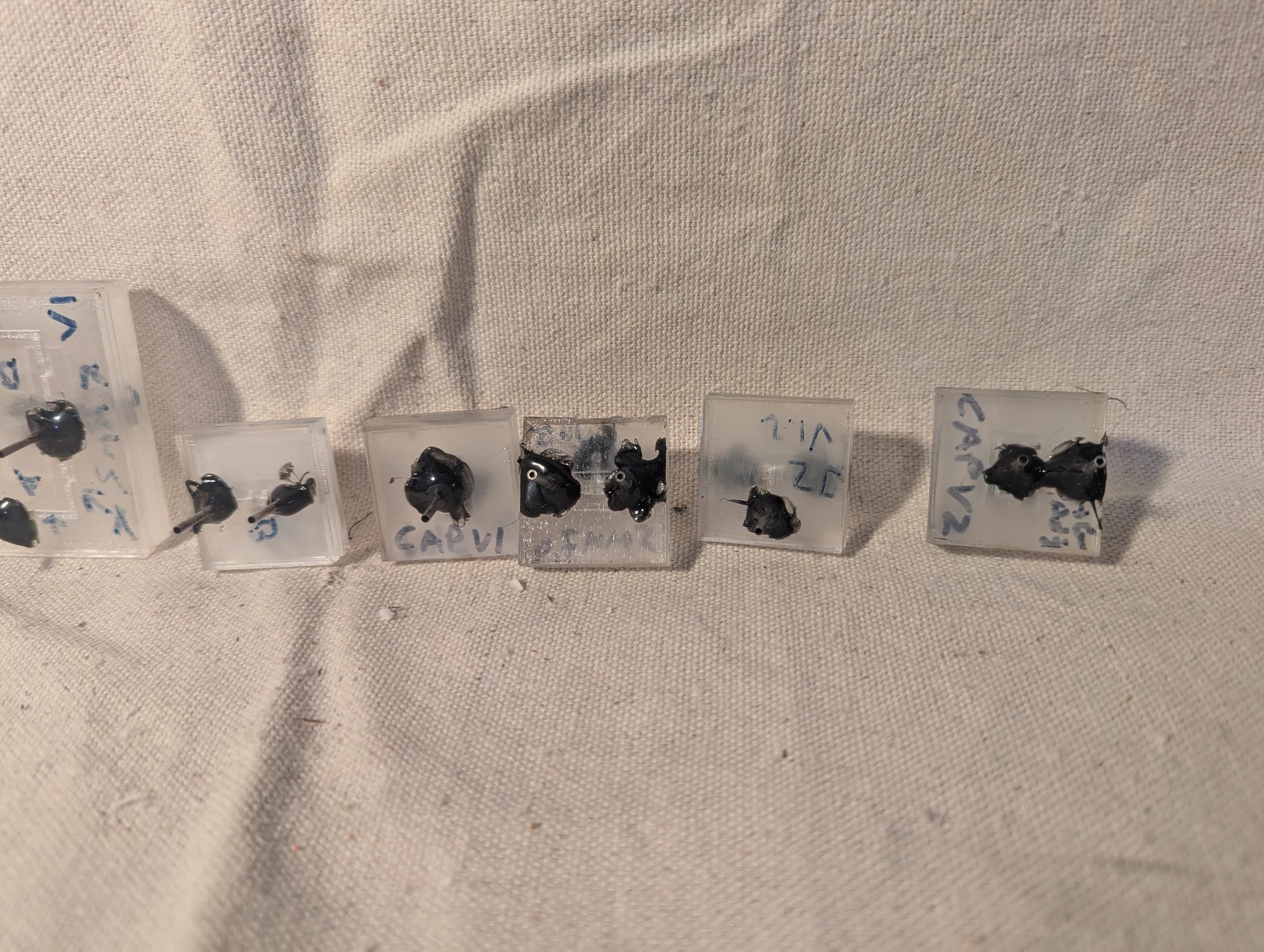
Early acrylic microfluidic devices, including Tesla valves: channel shapes intended to resist flow more in one direction than the other without moving parts. Before I developed heat-and-pressure bonding, I held thicker acrylic layers together with bolts and thin silicone gaskets. The collection may also include early pressure-controlled fluidic switches.
Another view of the Tesla-valve and microfluidic experiments. These assemblies used bolted acrylic plates and silicone sheets to seal the layers, preceding my later method of bonding thin acrylic chips with heat and pressure.
More devices from the microfluidic experiments. Before trying a moving fluorescent-dye segment for the display concept, I experimented with liquid gallium, or possibly a gallium–indium alloy. The metal spread over and adhered to the channel surfaces too readily, so it did not work well for the intended moving-droplet display.
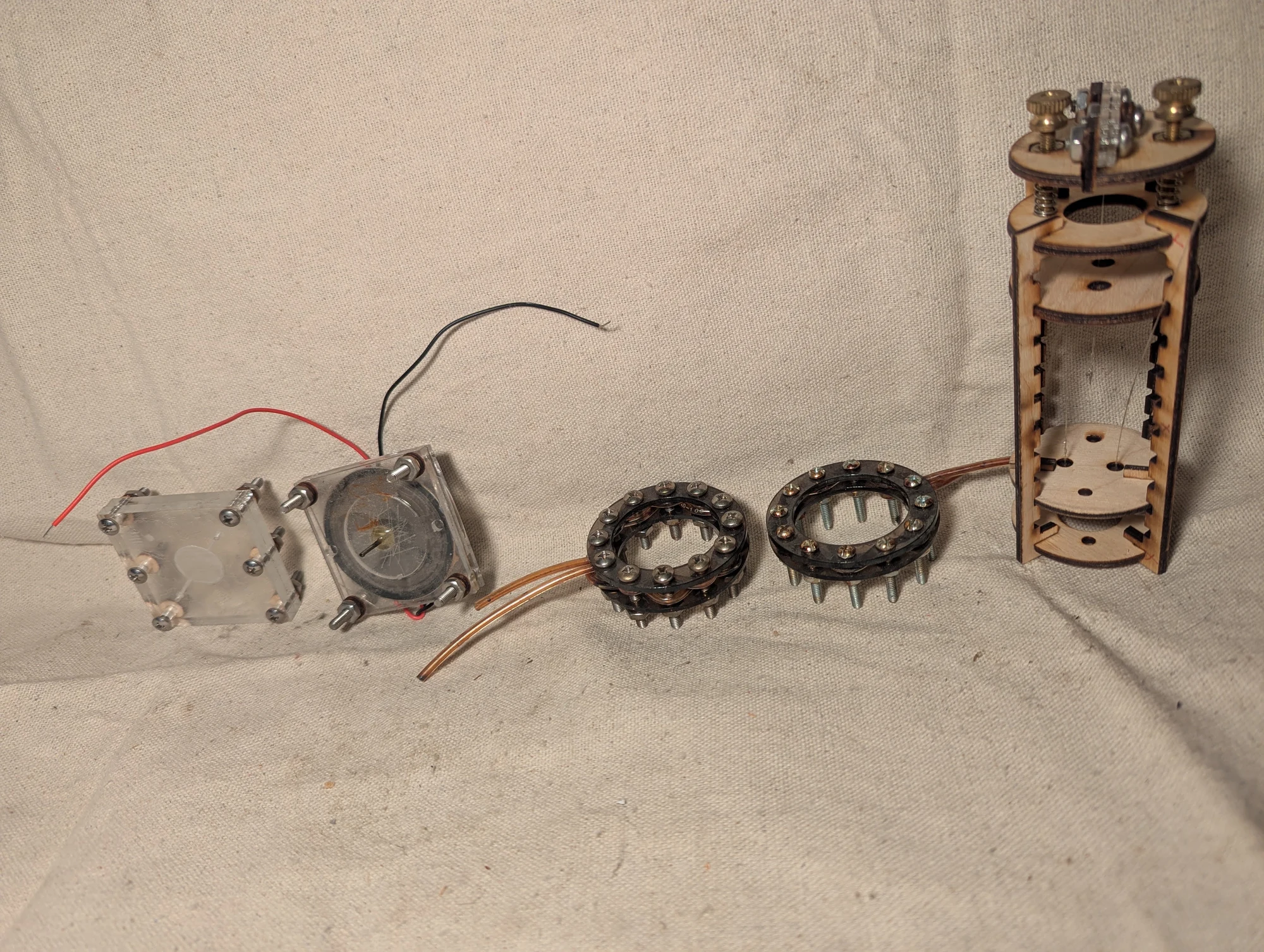
Among these assorted parts, the device on the right is a jig for pulling and twisting optical fibers together, then holding the arrangement with epoxy. The goal was to bring the fibers into close contact so light could pass between them. I eventually switched to commercially made fiber splitters, which were easier to use and gave better results.
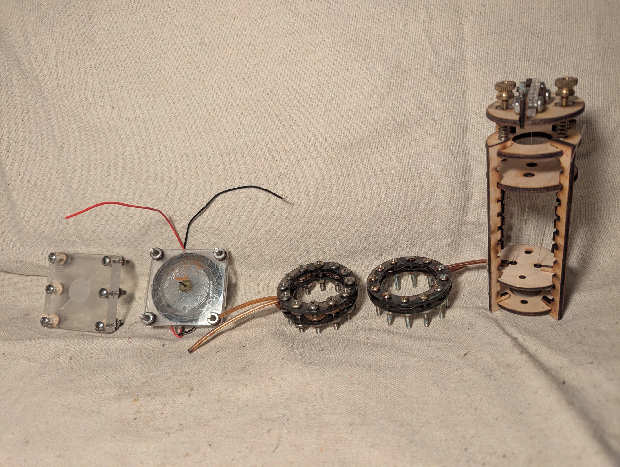
Another view of the assorted experimental hardware and the fiber-twisting jig at the right. The jig was part of an attempt to make a small optical splitter by bringing fibers together and fixing their arrangement with epoxy.
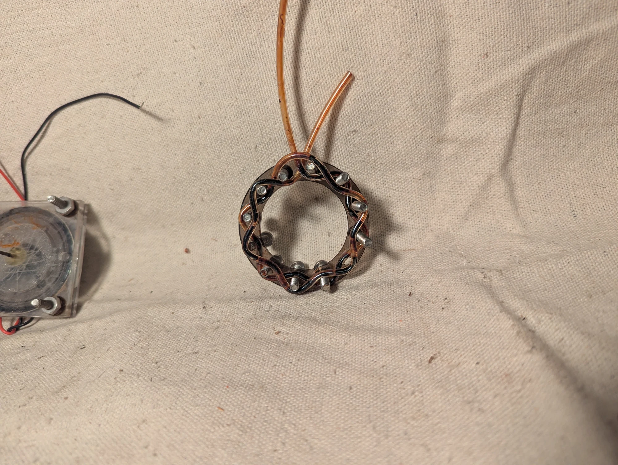
An experimental assembly intended to pump ferrofluid. I no longer recall the exact operating arrangement, and I do not remember getting this version to work.
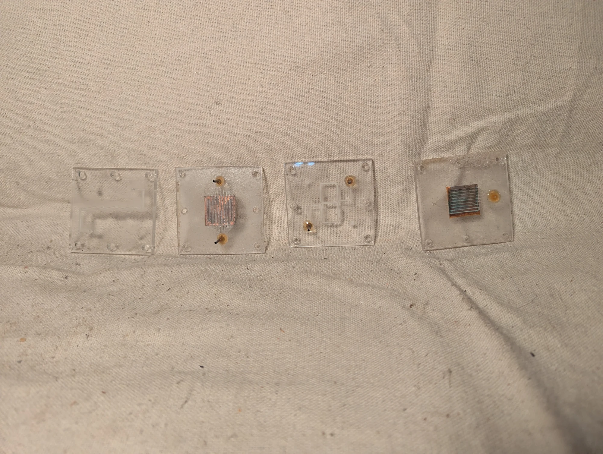
The figure-eight-shaped part is another version of the microfluidic display concept. A small segment of fluorescent dye was intended to move through the channel while timed ultraviolet flashes lit selected positions. This explored a different pattern from the earlier serpentine-channel design.
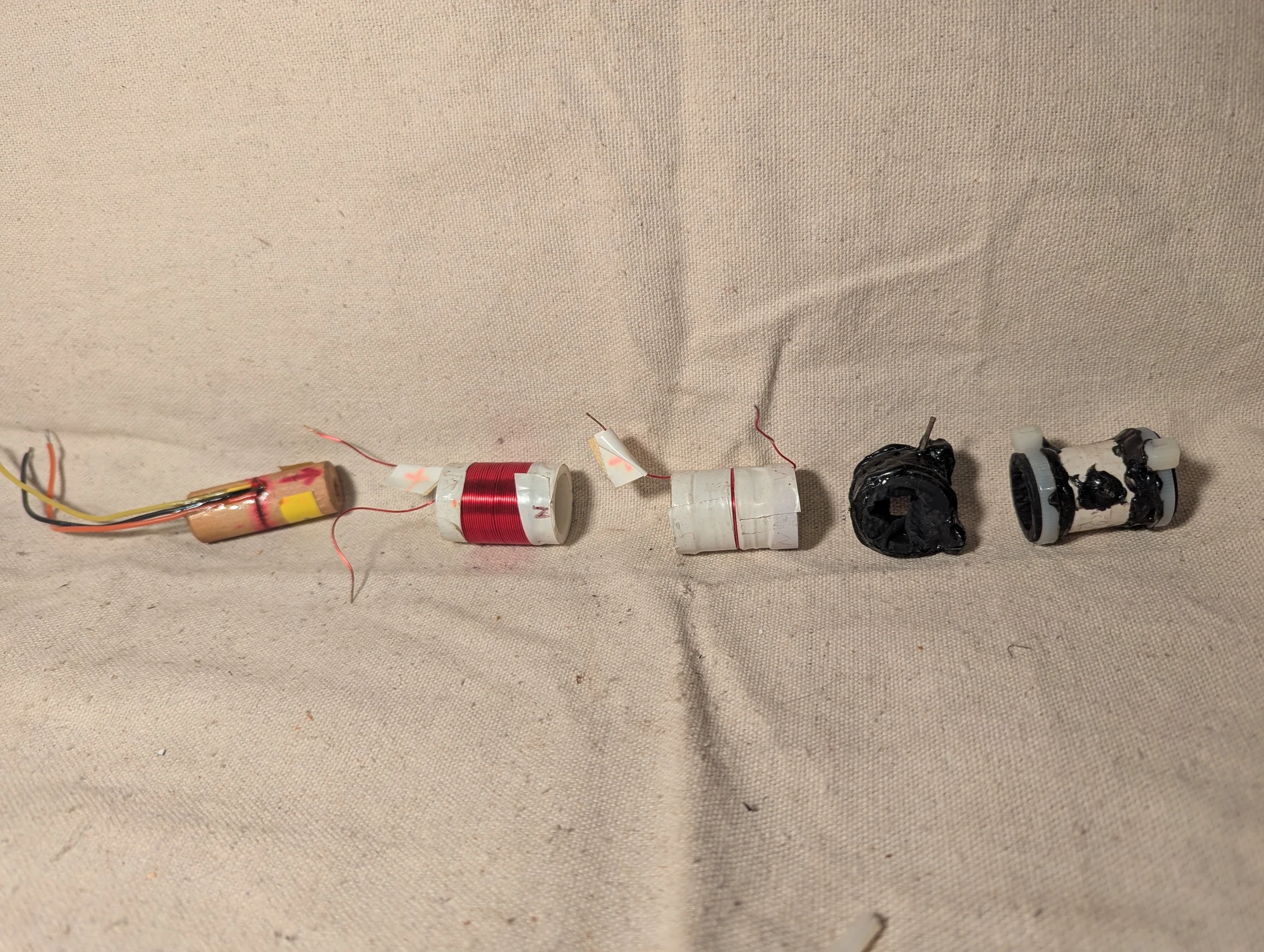
Components from a magnetic-field calibration experiment. I believe these belonged to the measurement-rig project for a physician client studying magnetic pulses. I no longer recall the exact role of each part.
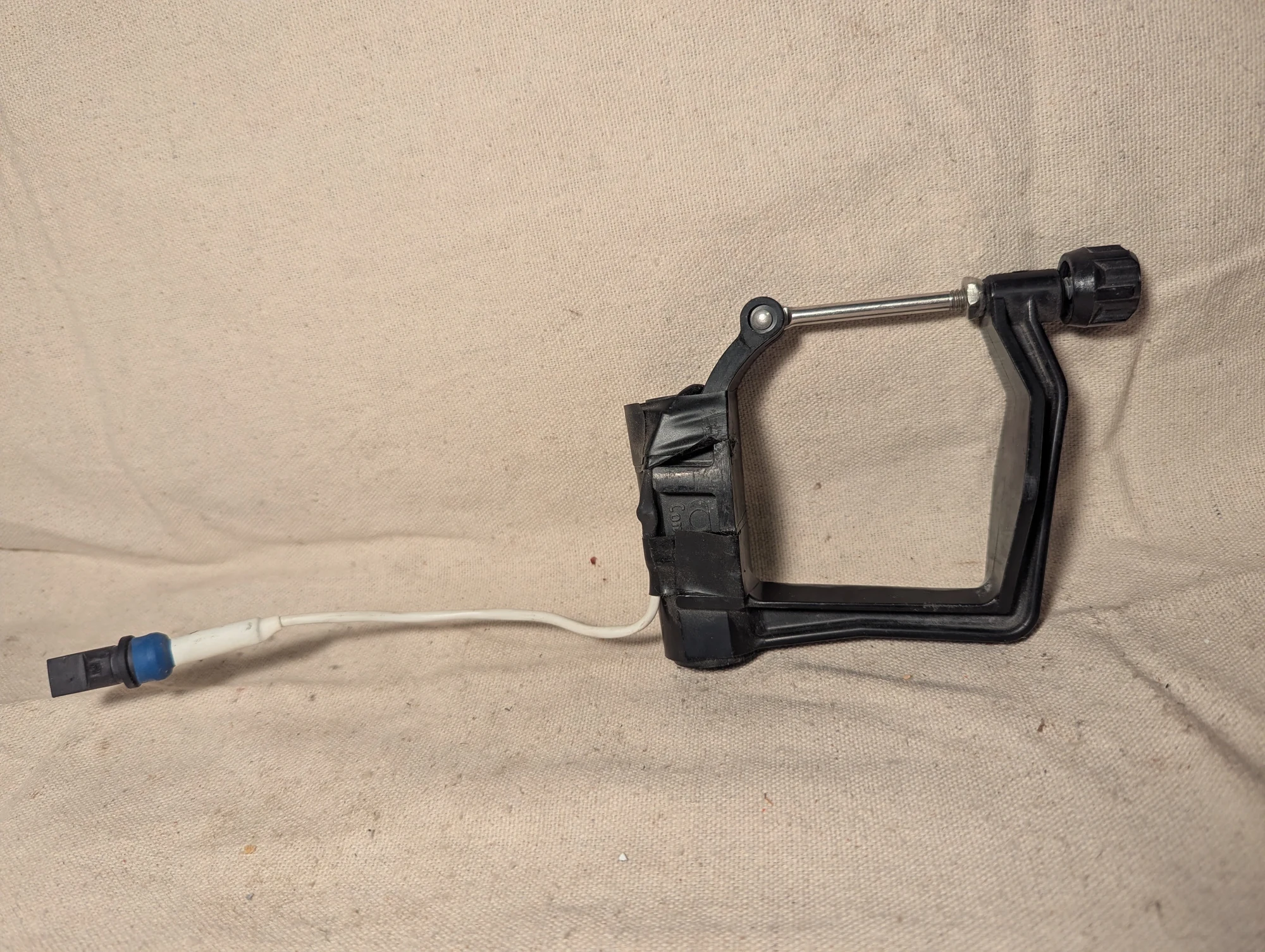
An oarlock fitted for an early stroke-sensing idea. A thin piezoelectric cable was positioned where the stroke load would squeeze it near the mounting bolt. I wanted to use its electrical response to changing load to track rowing effort. The idea was not developed into a calibrated measuring system.
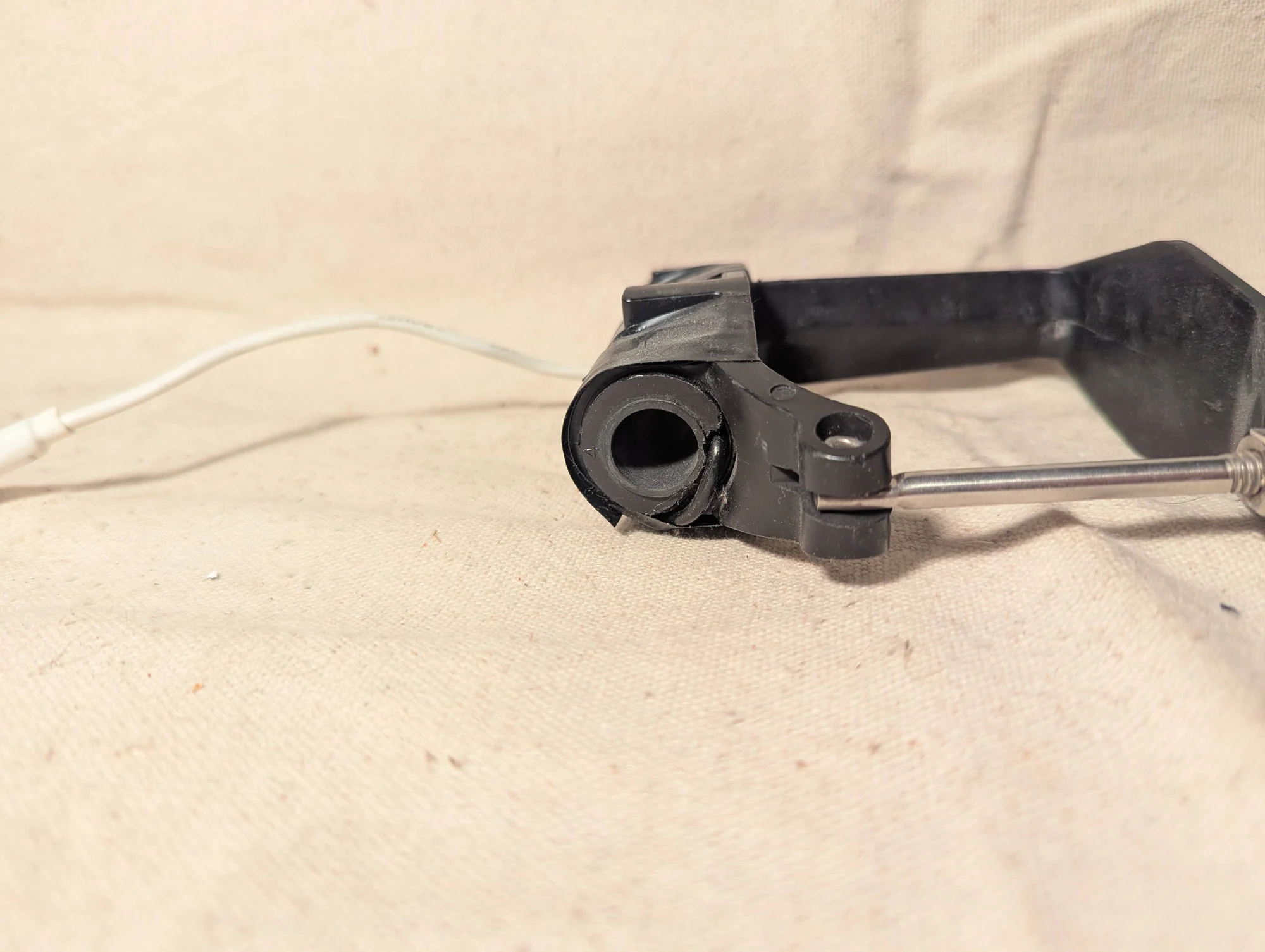
A closer view of the rowing-sensor experiment. The piezoelectric cable was intended to respond as the oar’s load compressed it against the mounting hardware during a stroke. I did not pursue the concept further.
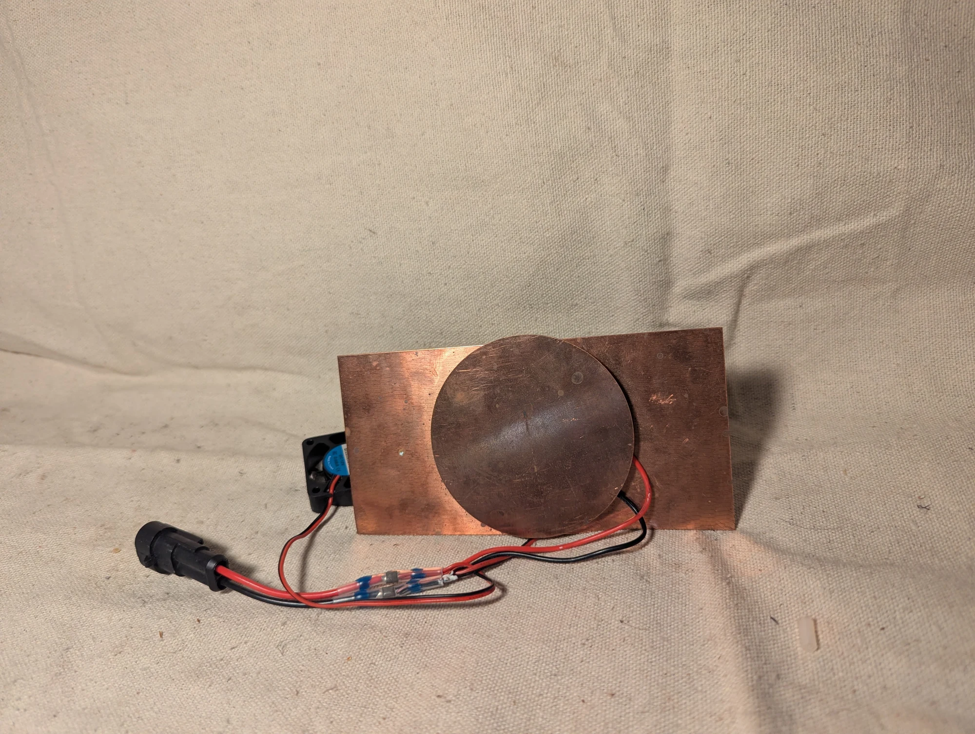
A phone-cooling experiment with a thermoelectric element, copper plates, and a block of paraffin wax. The wax was intended to absorb heat temporarily as it melted, giving the cooler a limited store of heat-absorbing capacity. Fans were added to help cool the assembly. The prototype did not provide as much cooling as I wanted.
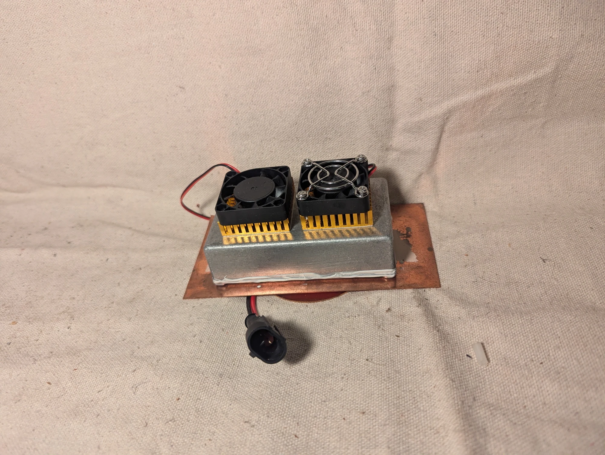
Another view of the thermoelectric phone-cooler experiment, showing the fans. Melting paraffin was intended to store heat during use, while the cooling hardware helped release that heat from the assembly. The overall cooling performance fell short of my expectations.
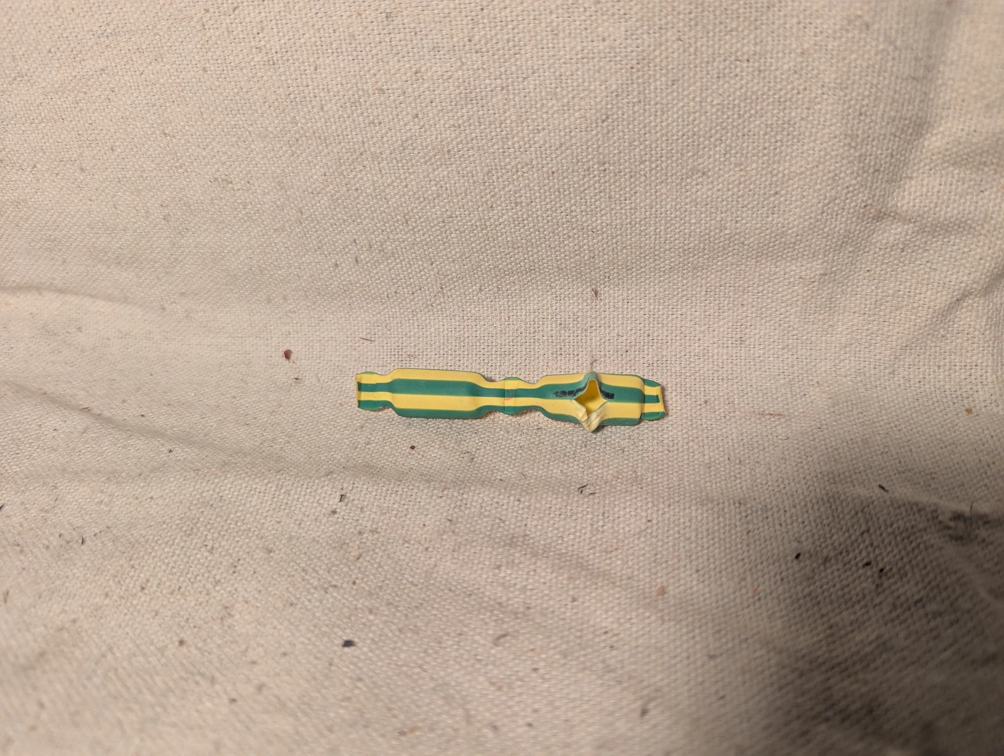
Another sample from the earlier flexible-tubing experiments exploring gas generation and pressure release. It documents one of the small experimental pieces from that project.
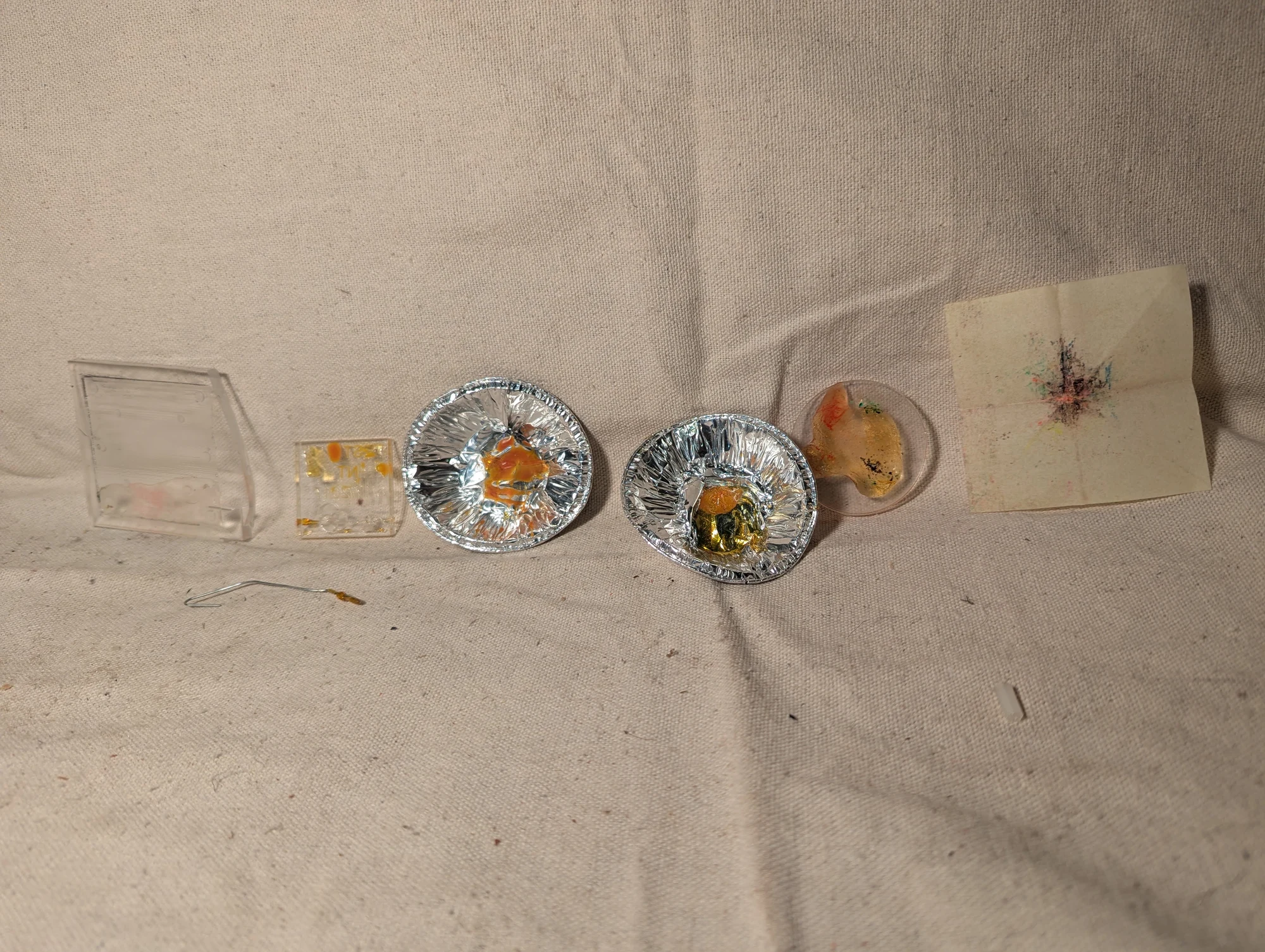
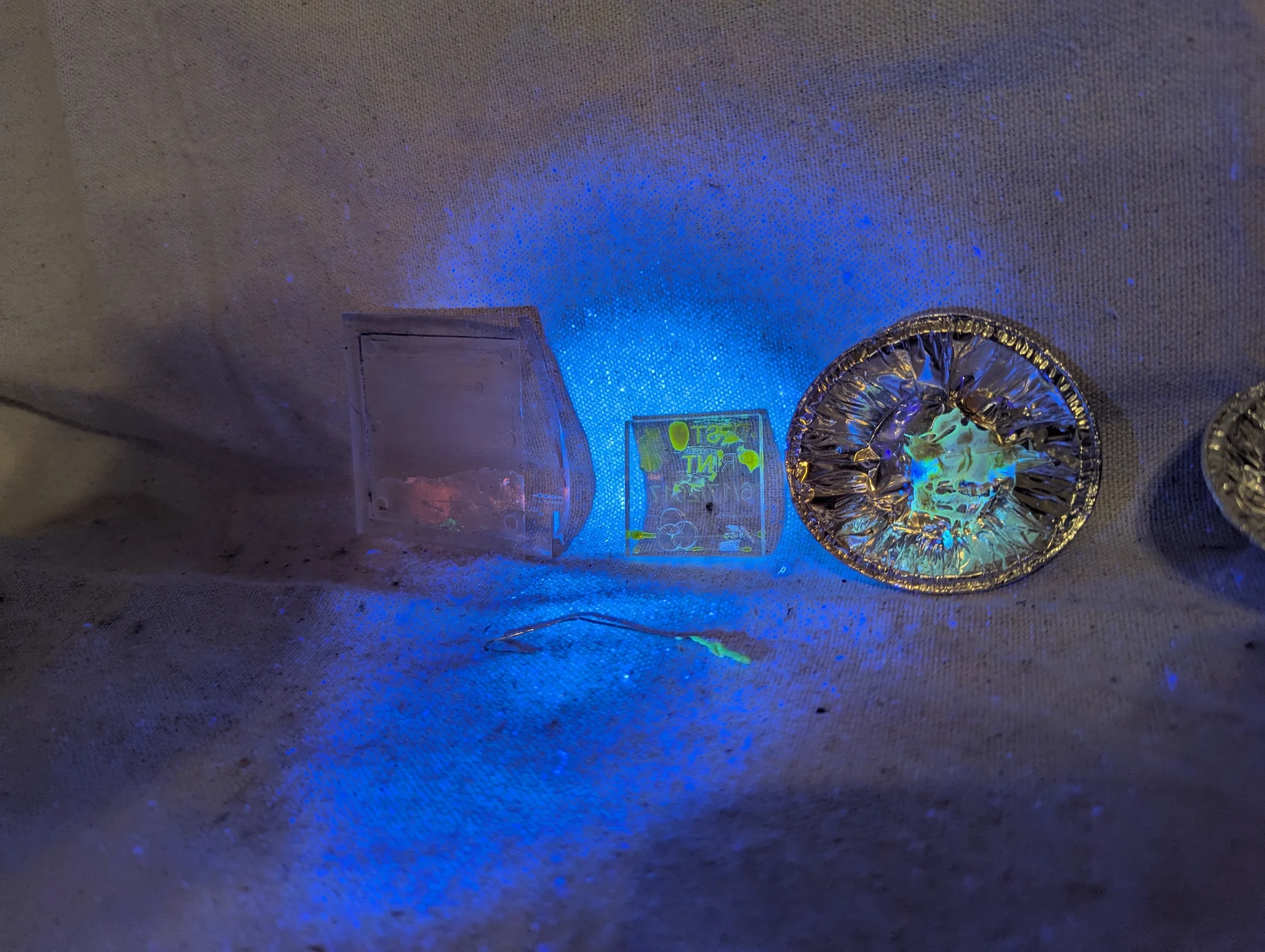
Samples made by mixing fluorescent dyes into epoxy. I used this material for the small glowing bead at the end of a fiber in the earlier optical experiment. I also pressed fluorescent epoxy into engraved acrylic patterns to explore different illuminated shapes.
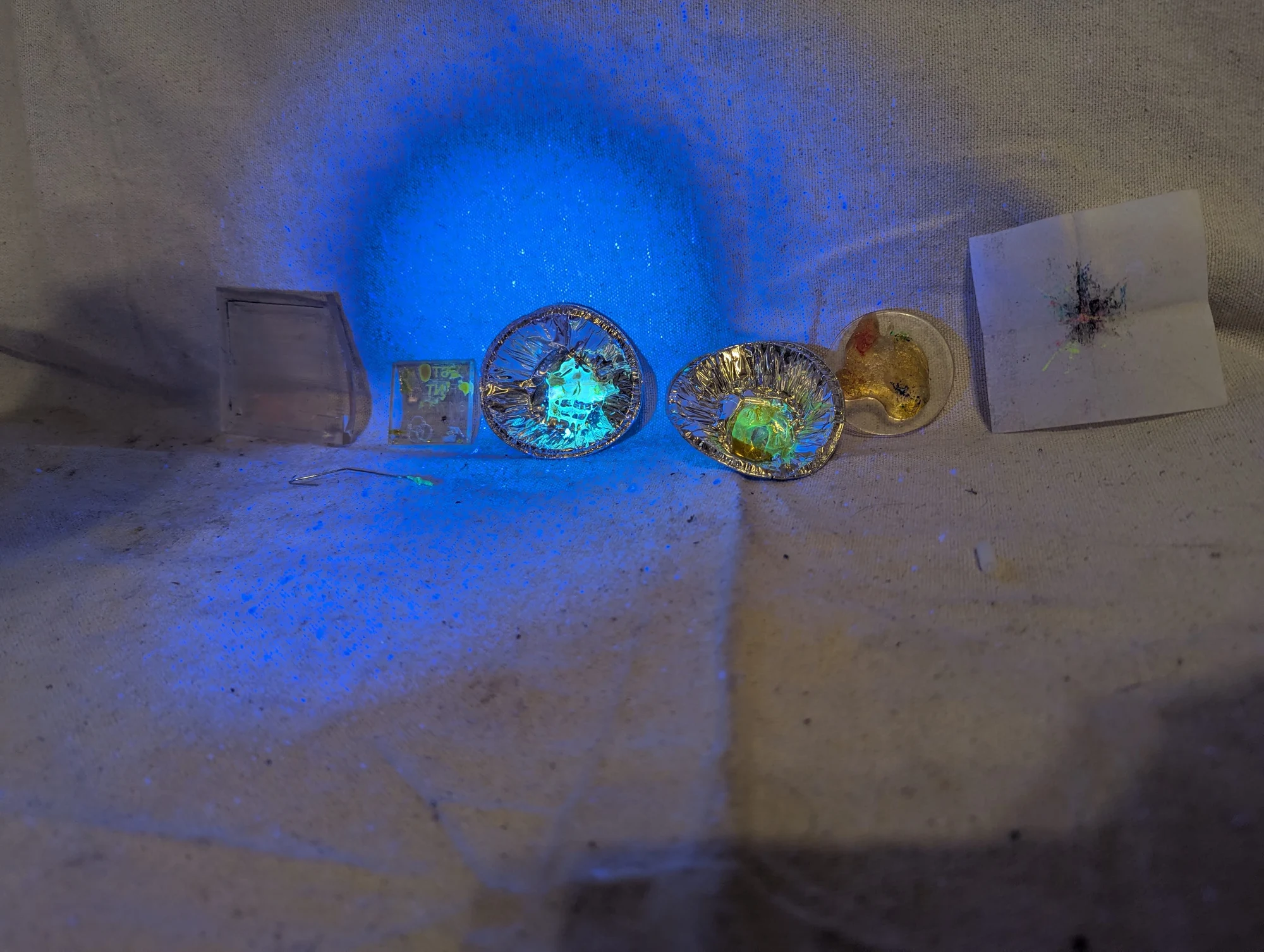
The fluorescent epoxy samples illuminated with ultraviolet light, showing their colored emission. These material experiments supported both the fiber-end bead and the filled acrylic patterns.
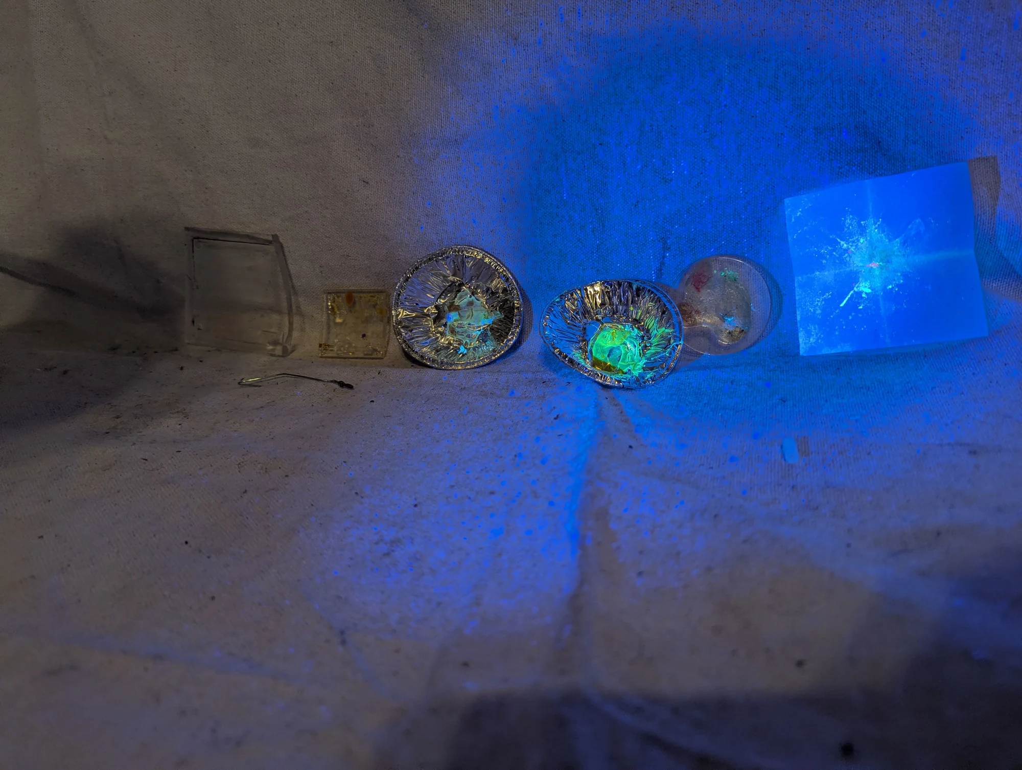
Another view of the epoxy-and-dye experiments under ultraviolet illumination. The samples include small cast pieces and patterns formed in acrylic.
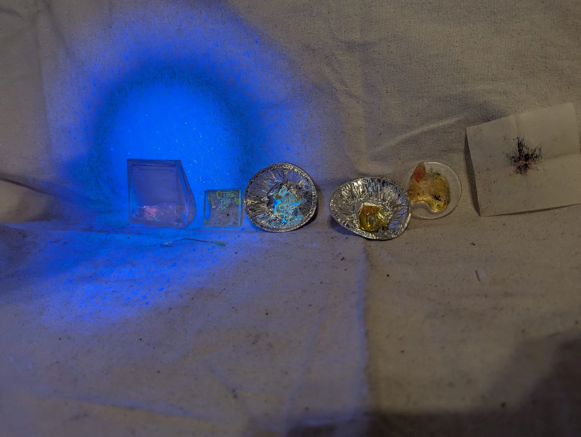
A further view of the fluorescent epoxy samples. Illuminating the pieces with ultraviolet light let me see how the colored material appeared in different shapes.
A closer view of the epoxy samples and filled acrylic patterns under ultraviolet light. These were exploratory trials of fluorescent materials for small optical and decorative elements.
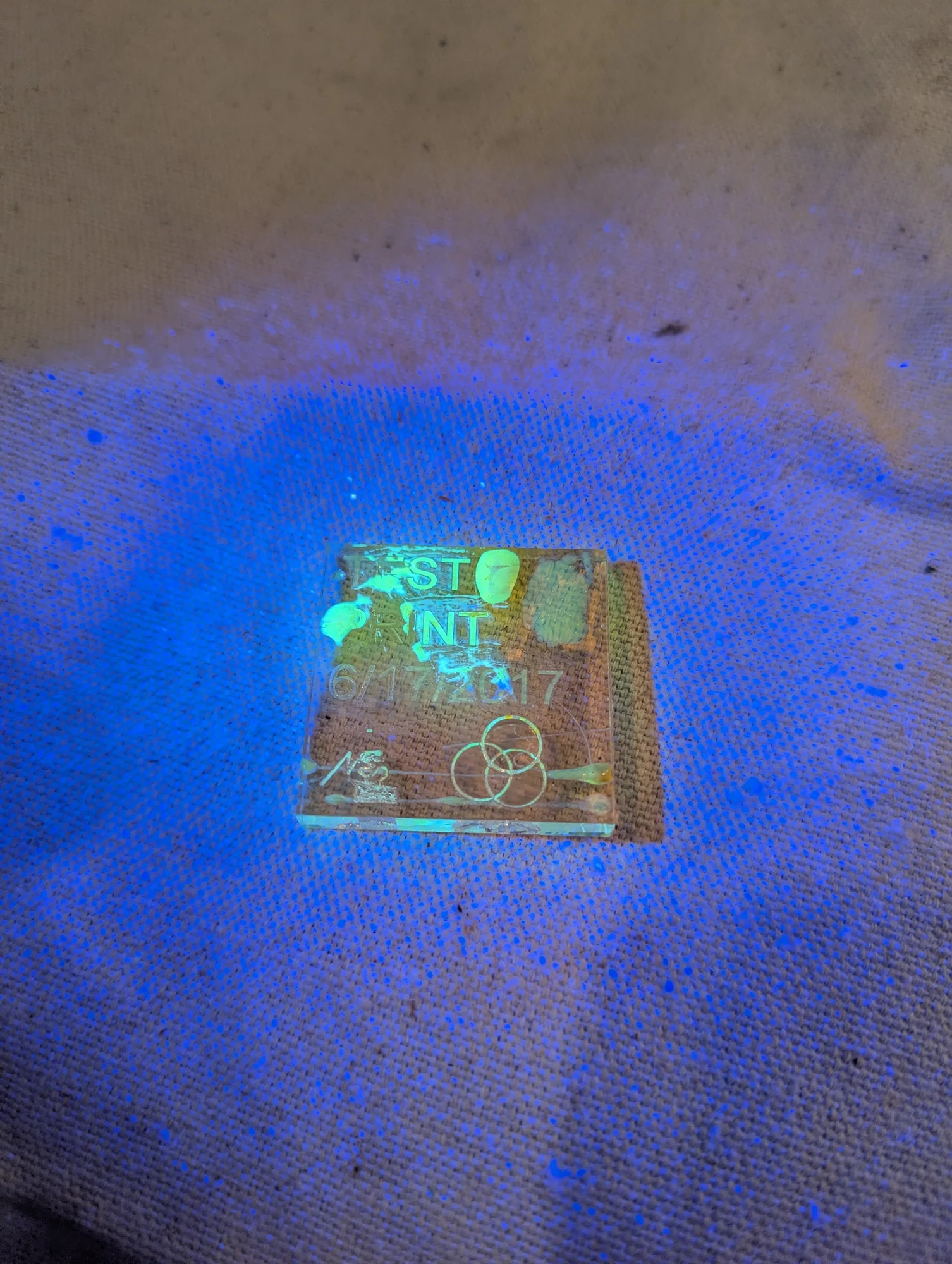
An engraved acrylic piece with fluorescent epoxy pressed into its pattern. Ultraviolet illumination makes the filled areas glow, highlighting the shapes in the surface.
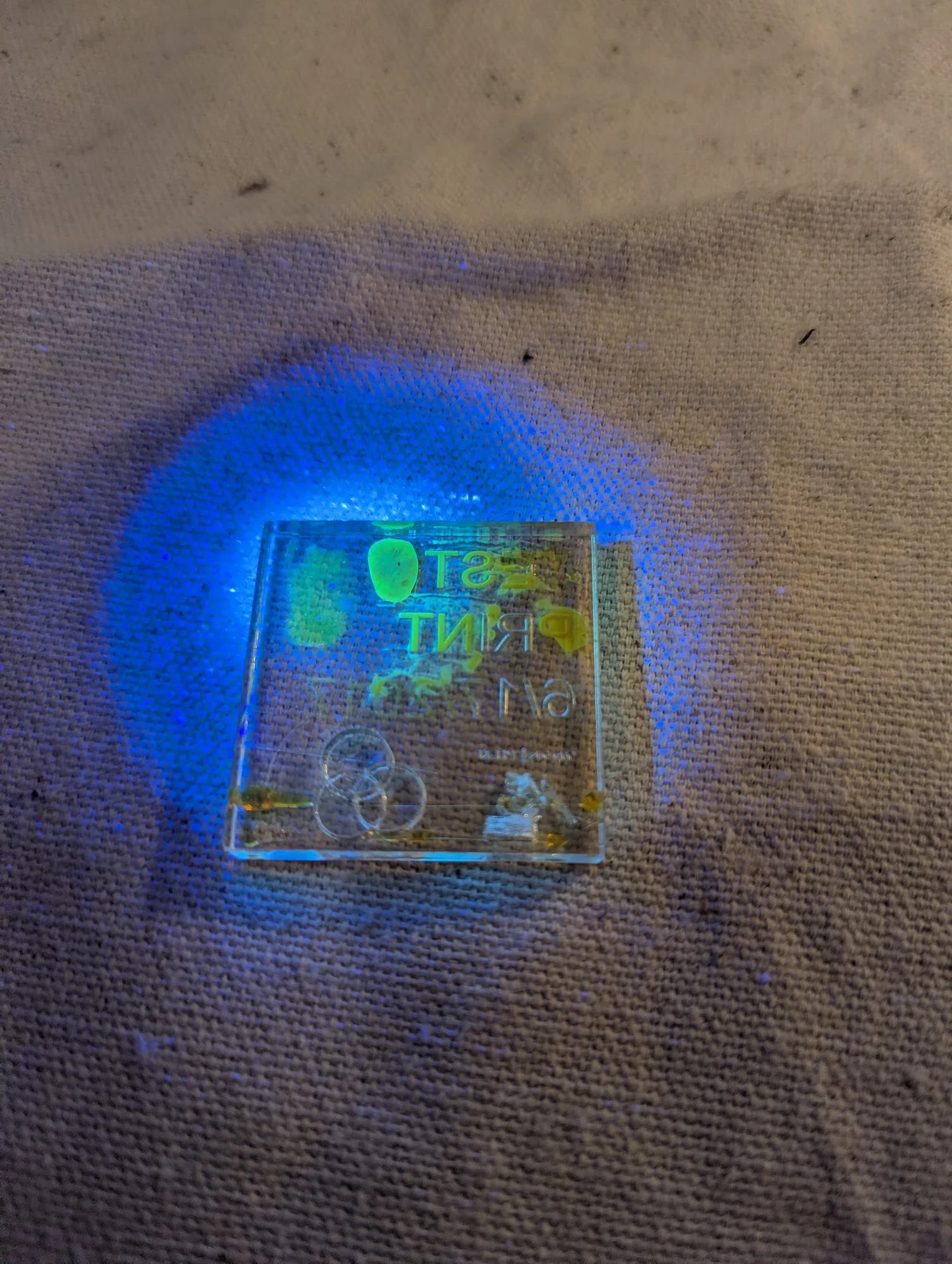
Another view of the engraved acrylic and fluorescent epoxy under ultraviolet light. This was part of the same series of material experiments used to develop the fiber-end fluorescent bead.
Photos 500–504
Batch 10 · 3 photographs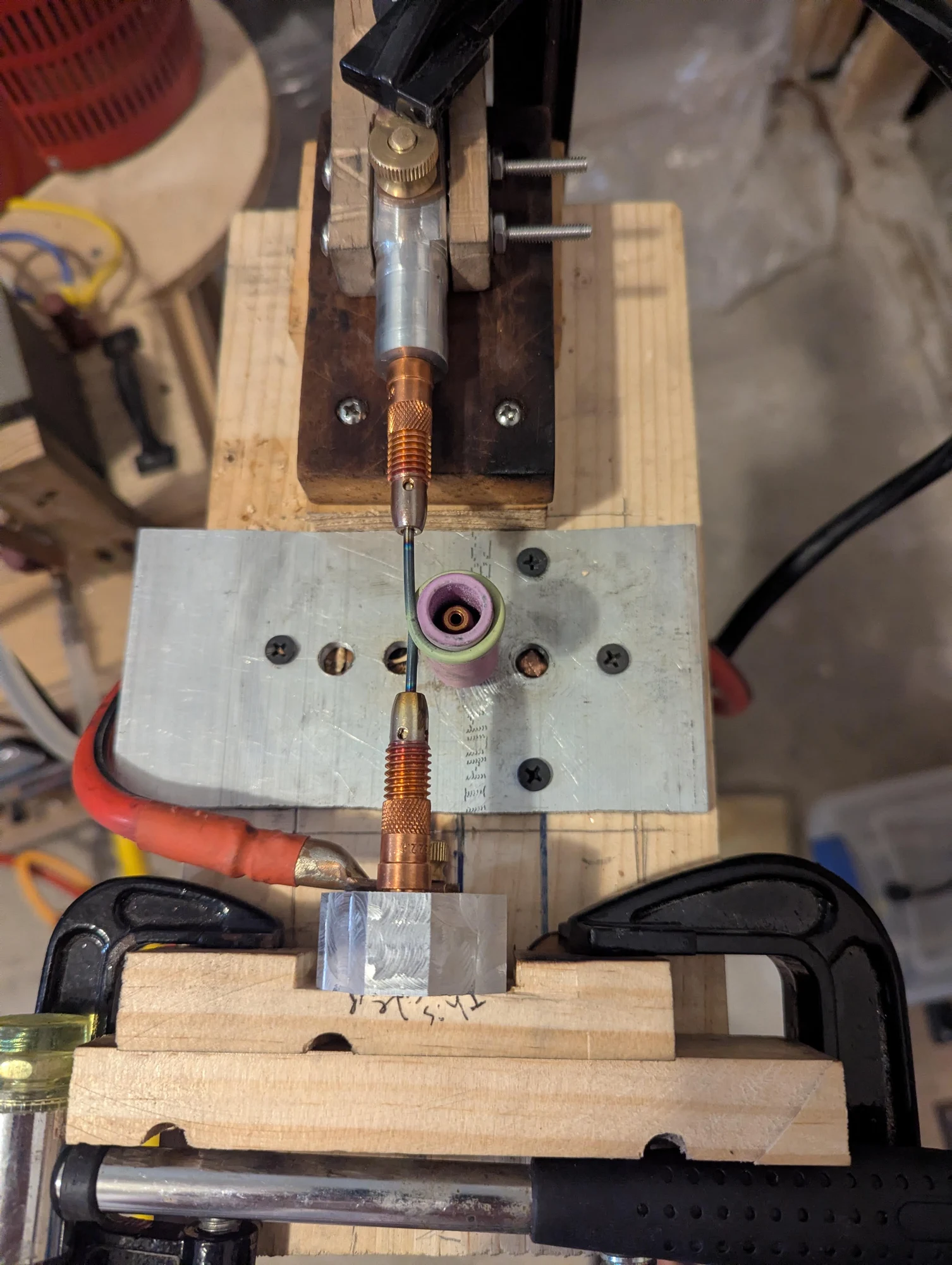
This is the fixture I currently use to wind tungsten rod into a furnace filament. It uses aluminum tooling, with one electrode holder fixed while the other moves around the mandrel that guides the bend. The fixture supports the rod as I shape it.
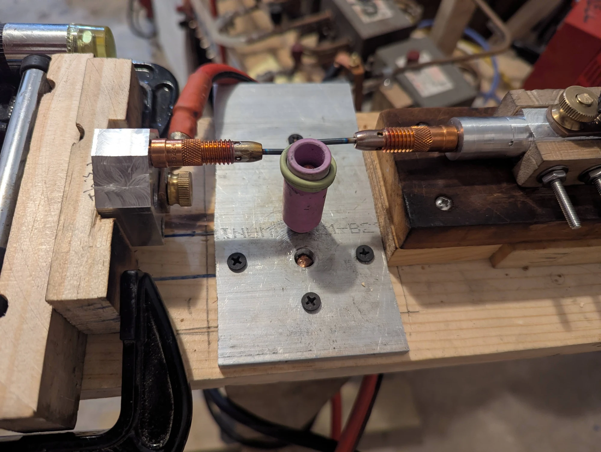
Another view of my current tungsten-filament winding setup, showing the two electrode holders and the mandrel. The clamps and supports hold the assembly in position during forming.
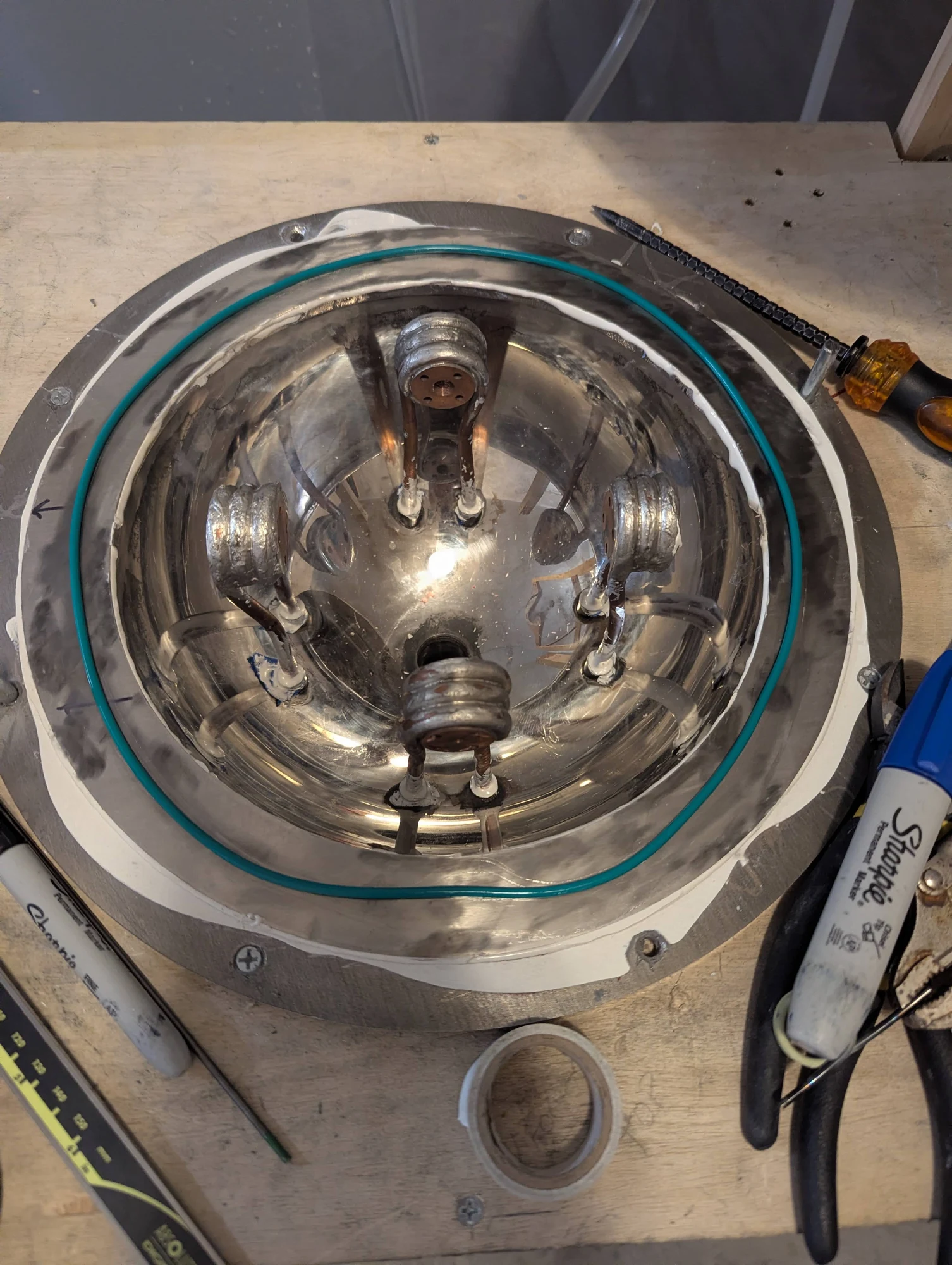
The inside of the stainless-steel furnace hemisphere after the electrode feedthroughs were fixed in place with epoxy. This shows a later stage of the assembly previously photographed with temporary clamps.
Photos 508–521
Batch 12 · 7 photographs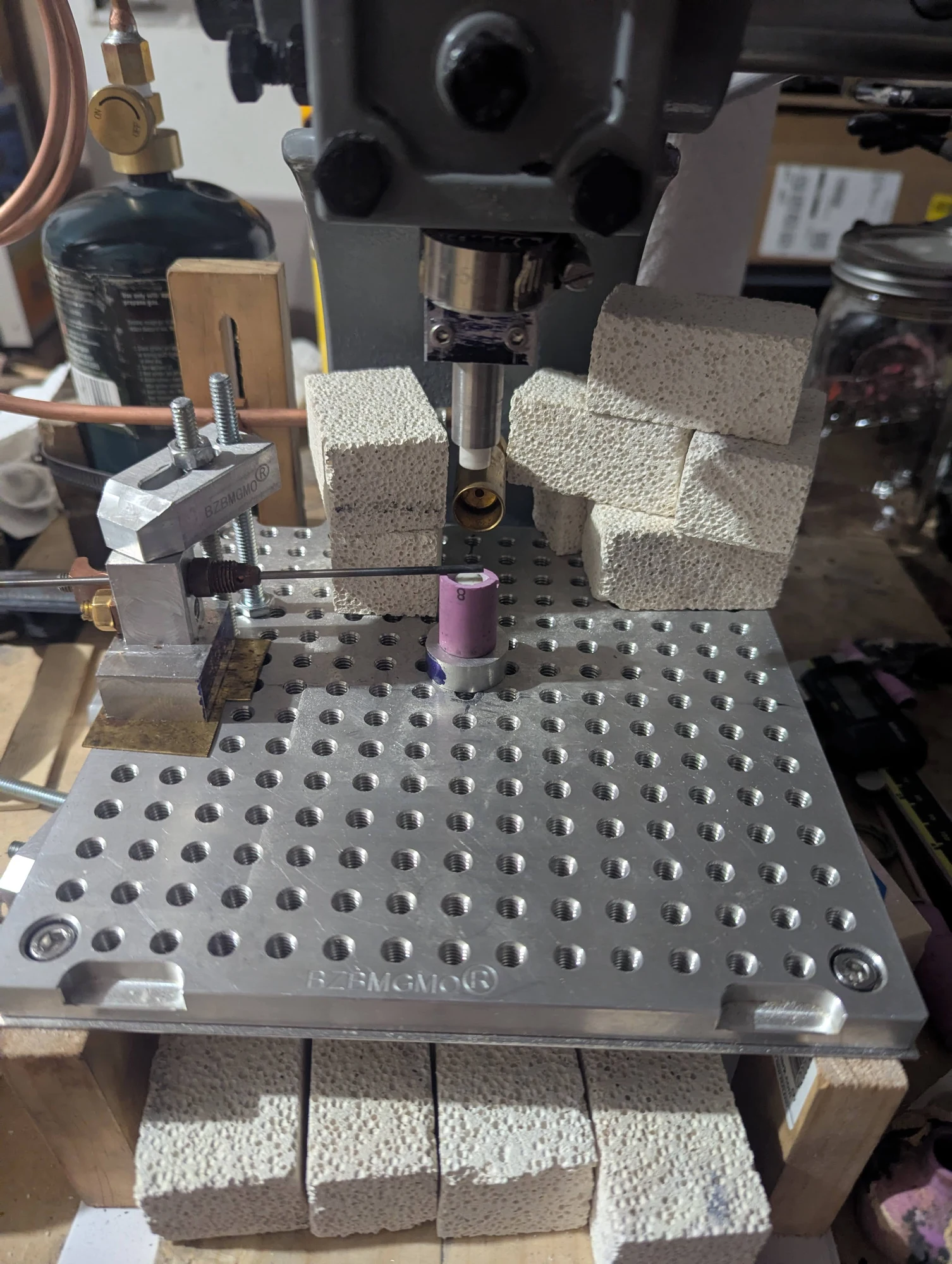
An arbor press fitted with a zirconia ceramic pressing head for shaping tungsten rod. I used a propane torch to heat the rod, then the press to form a small offset so the part would fit inside the furnace. Insulating blocks surrounded the working area to help retain heat.
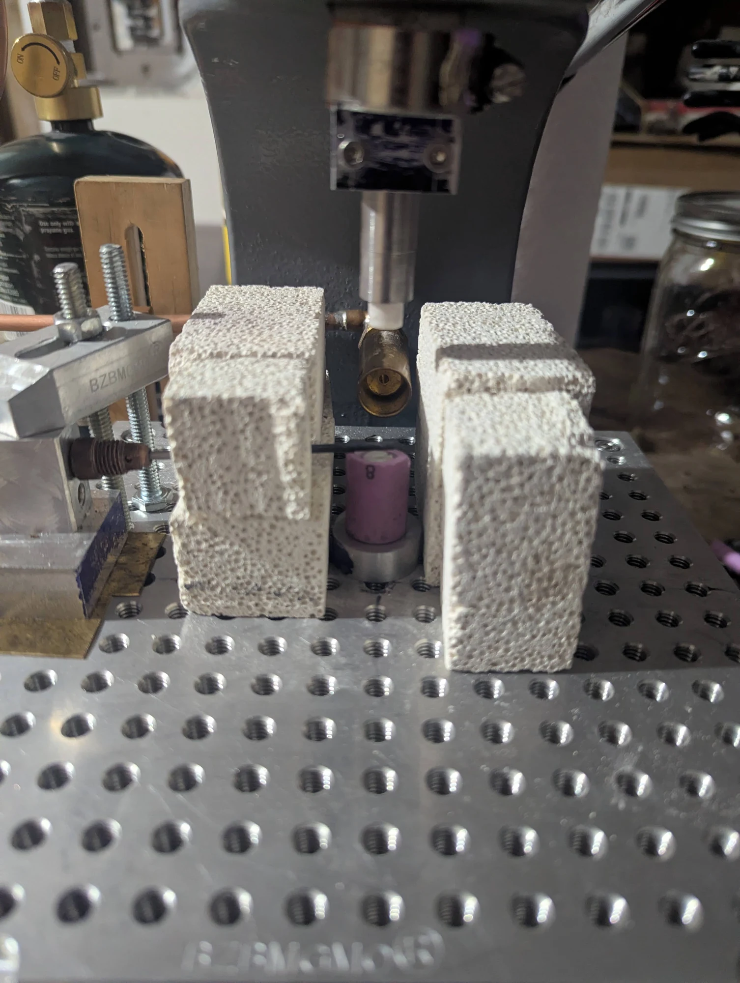
A closer view of the modified press, with the ceramic head above the tungsten-forming area. The surrounding insulating blocks helped limit heat loss while the rod was heated.
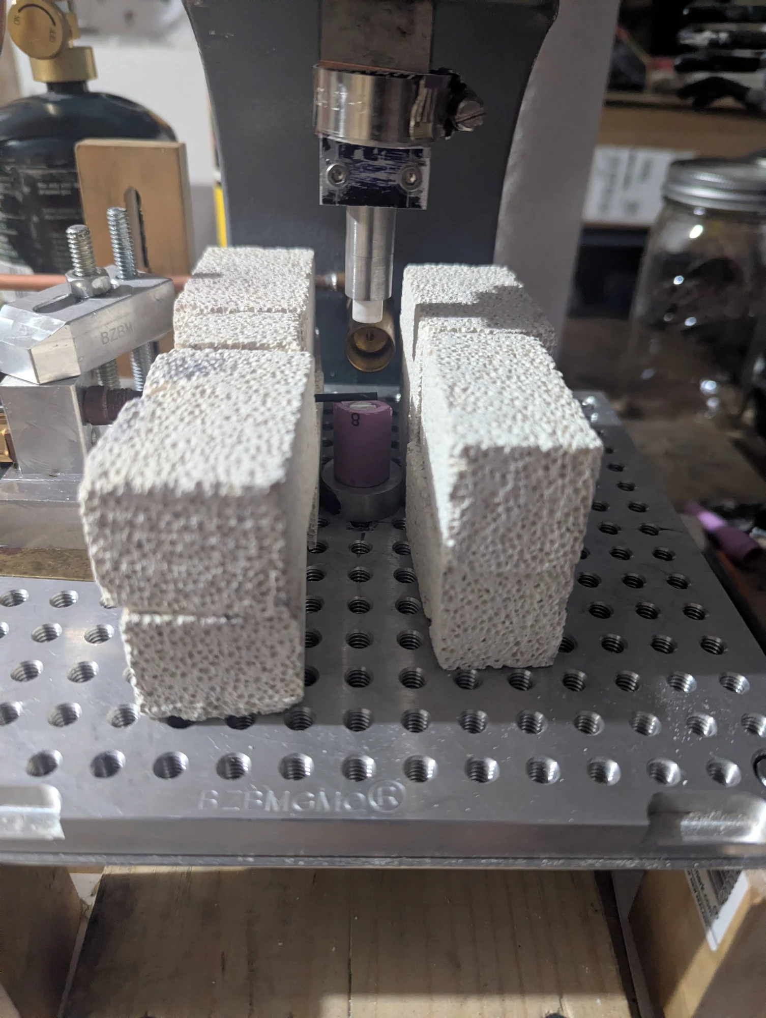
A further view of the fixture used to support the tungsten rod beneath the ceramic pressing head. The goal was to add an offset that would let the rod fit the furnace assembly.
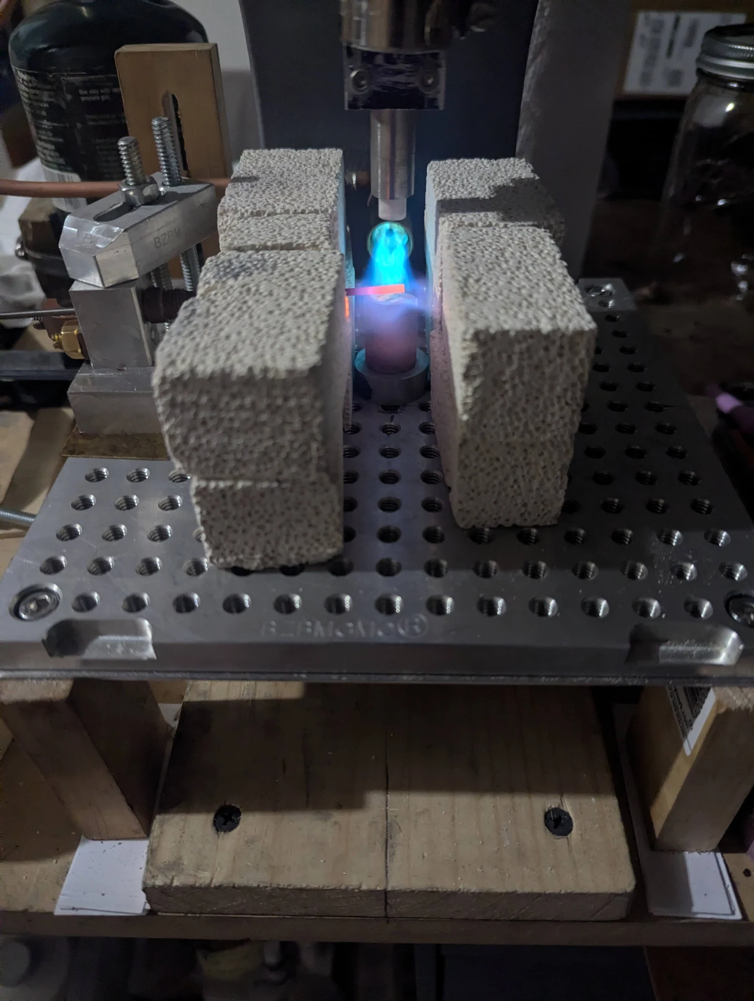
The propane torch heating the tungsten in the insulated work area. The press was used to form the required offset after heating.
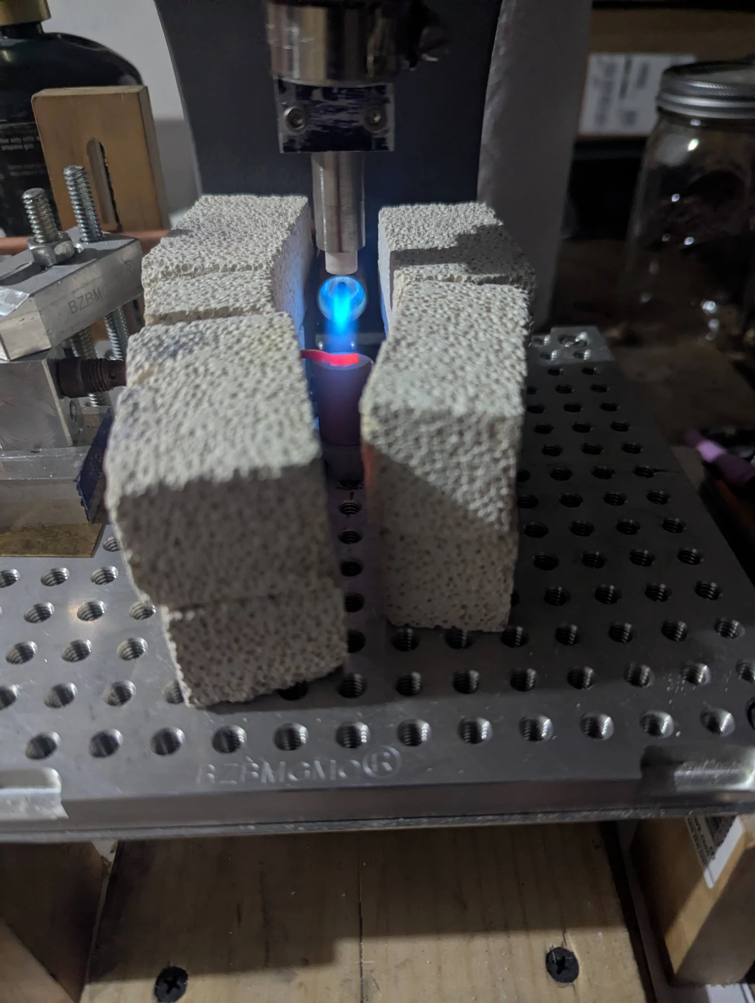
A further photograph of the heating stage. The arrangement kept the torch, insulating blocks, and pressing tool together around the section of tungsten being shaped.
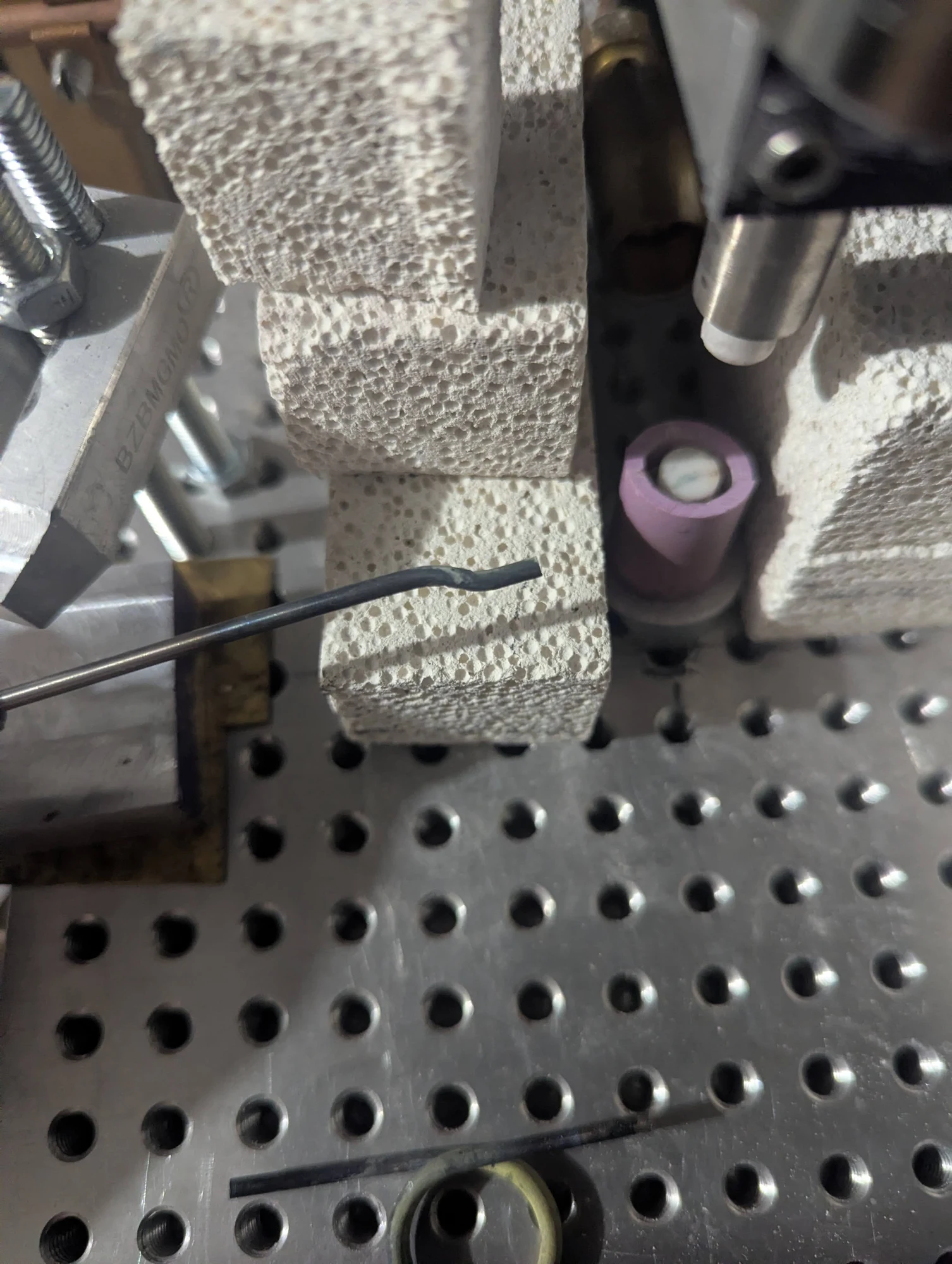
A close view of the shaped tungsten rod beside the ceramic tooling. The offset was made to accommodate the rod’s position inside the furnace.
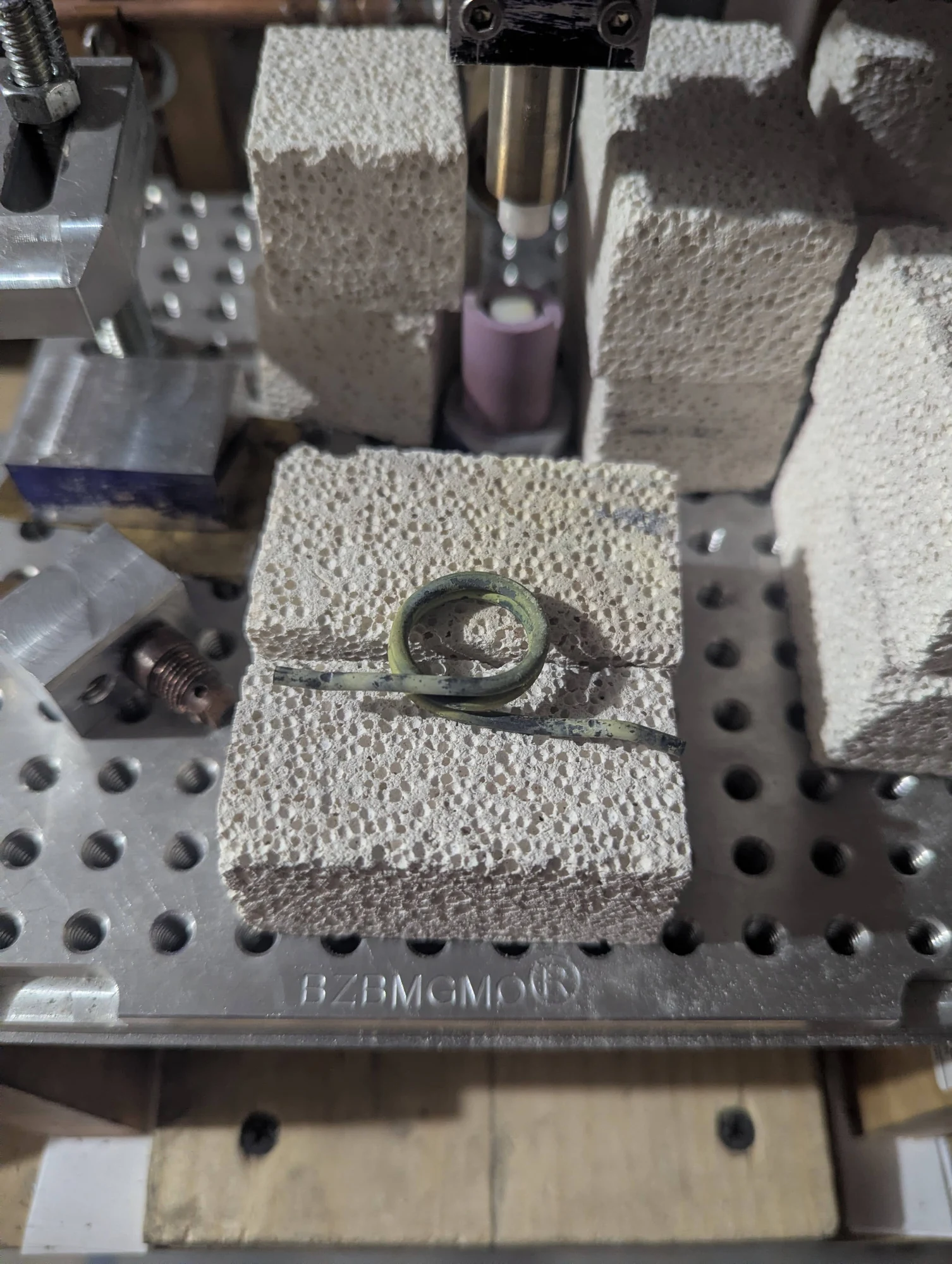
The tooling and tungsten pieces at the press after a forming step. This view records the small working area used to adapt the rod’s shape to the furnace.