Contract work / Sensors & electronics
Magnetic-field measurement rig
An adjustable coil-and-sensor rig developed with magnetic-field simulation and oscilloscope testing.
Open the numbered review →Assembled rig and testing
Photos 225–226
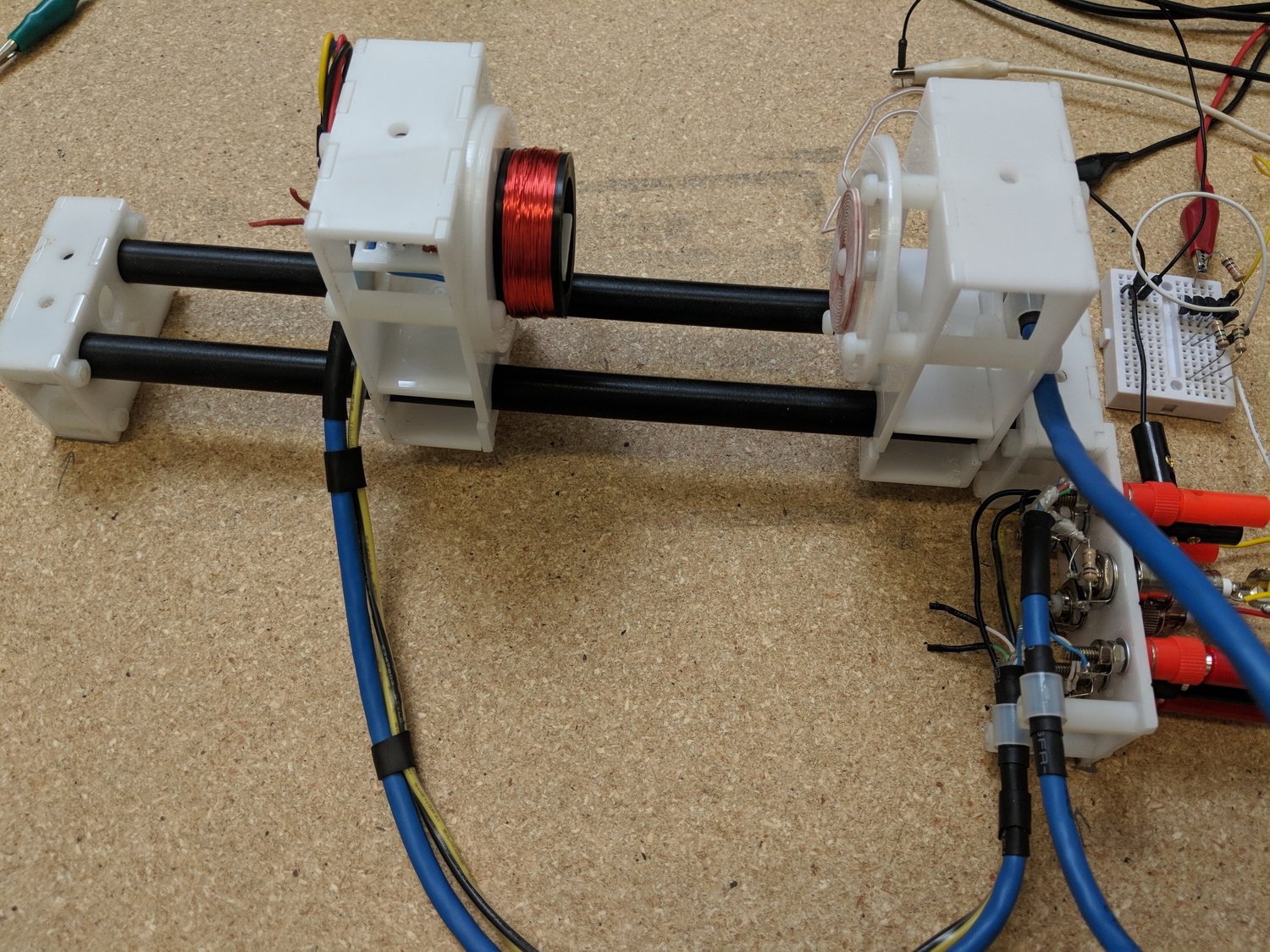
I built this rig for a client who wanted to characterize magnetic pulses. The finished assembly stayed close to my CAD model: a flat coil produced the field, while an adjustable sensor mount let me change where I measured it. A separate coil provided a way to adjust the background magnetic field during testing.
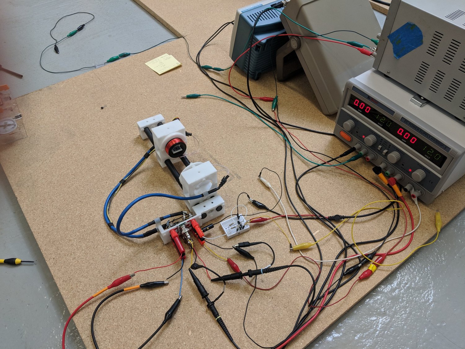
I applied a test signal to the coil and watched the magnetic sensor’s response on an oscilloscope. I recall using a pulsed or square-wave signal, although I would need my original notes to confirm the waveform. In retrospect, I would consider a Helmholtz coil arrangement for a more uniform test field; this single-coil setup was enough for the experiments I was doing at the time.
Related calibration components
Photo 484
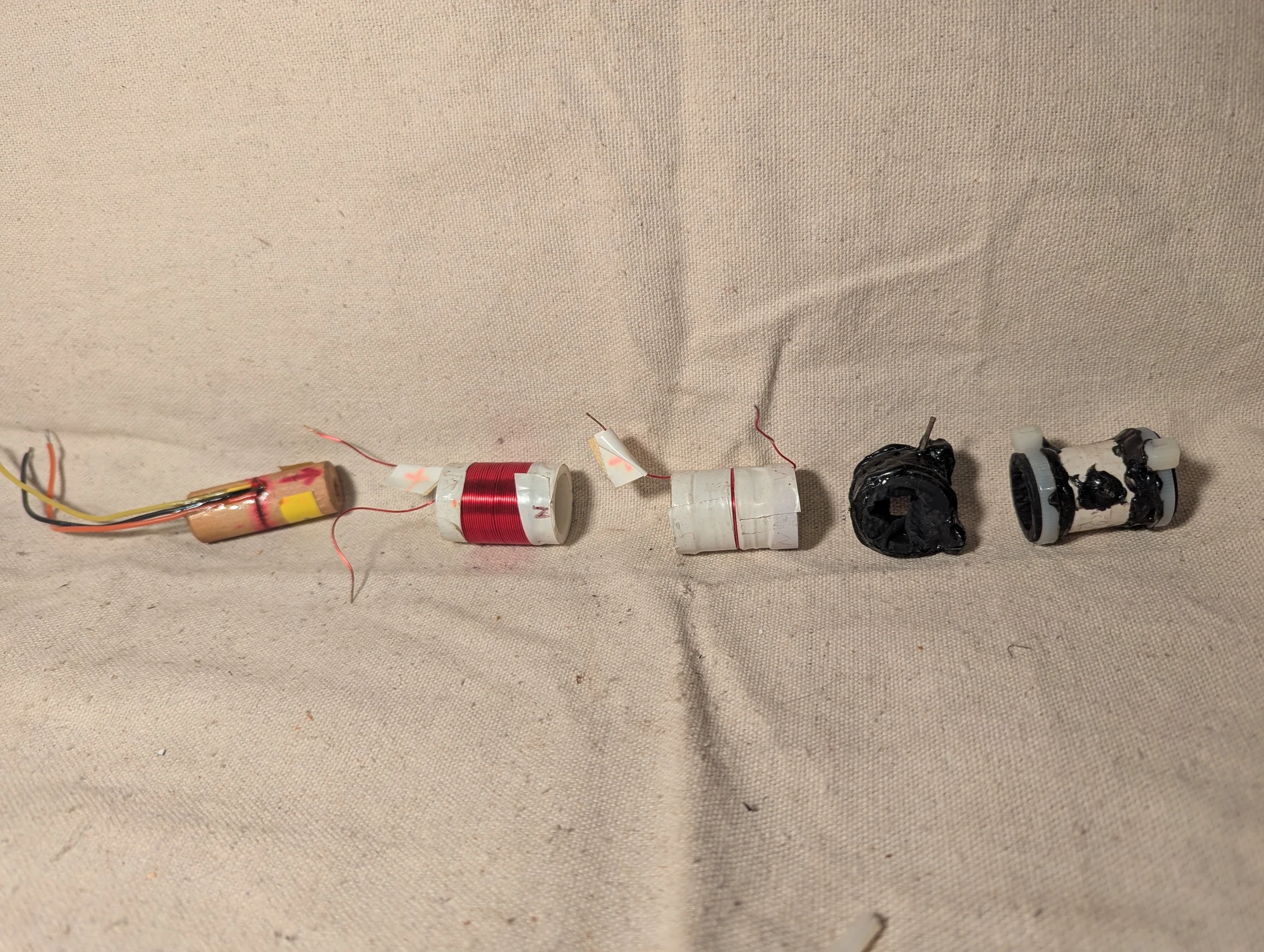
Components from a magnetic-field calibration experiment. I believe these belonged to the measurement-rig project for a physician client studying magnetic pulses. I no longer recall the exact role of each part.
Design model and simulation
Photos 224, 227
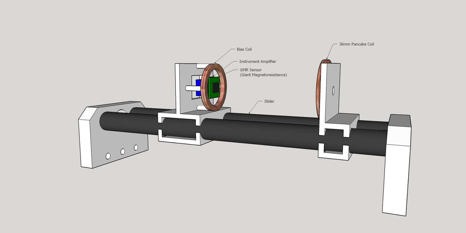
A 3D model I made for a physician client's magnetic-pulse research. A sliding fixture adjusted the separation between a flat pancake coil and a magnetic-field sensor, labeled GMR in the model. A second coil around the sensor was intended to adjust the background magnetic field, with an amplifier included for reading the sensor signal. The rig was designed to help characterize the field produced by the experimental coil.
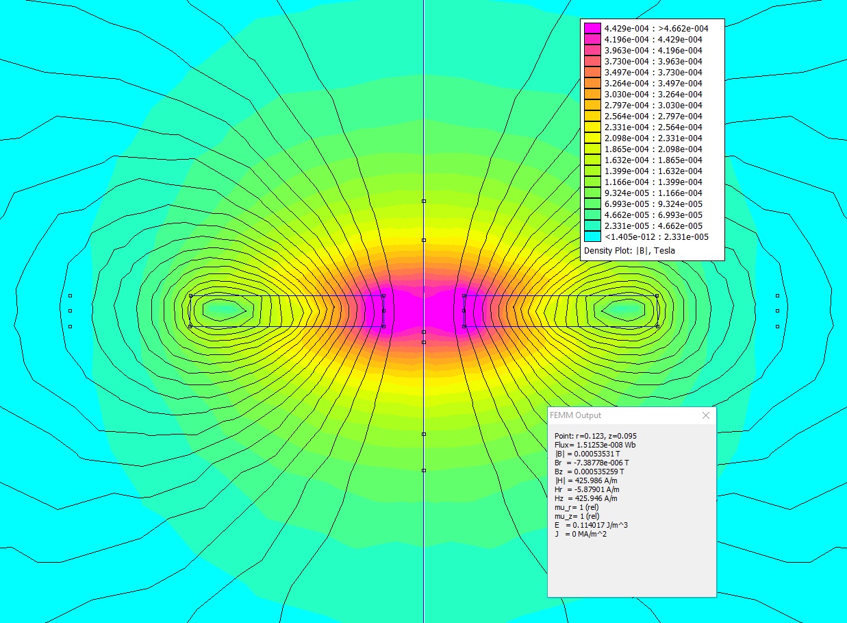
I used FEMM, a finite-element simulation program, to estimate how the magnetic field would be distributed around the coil. The field lines and color map helped me compare the geometry with the region I wanted to measure. This is a simulation result, rather than a measured field map.
Need a prototype for your project?
Tell me what you need to build and which constraints matter. We can discuss whether my experience fits your project.