Personal projects / Fluids & cooling
Magnetic-refrigeration experiments
Explorations of magnetic cooling with gadolinium and ferrofluid, supported by custom controls and temperature measurements.
Open the numbered review →Fluid-transfer and temperature measurements
Photos 409–410
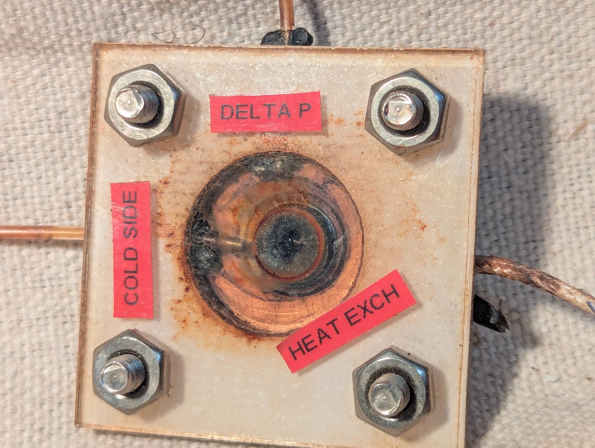
An experiment combining pressure-driven fluid movement with temperature measurements. Tygon tubes accessed positions close to the strongest part of the magnetic field and farther away. I was exploring whether these locations would contain fluid at different temperatures, and whether moving that fluid could transfer heat. The thermocouples were used to look for the resulting changes.
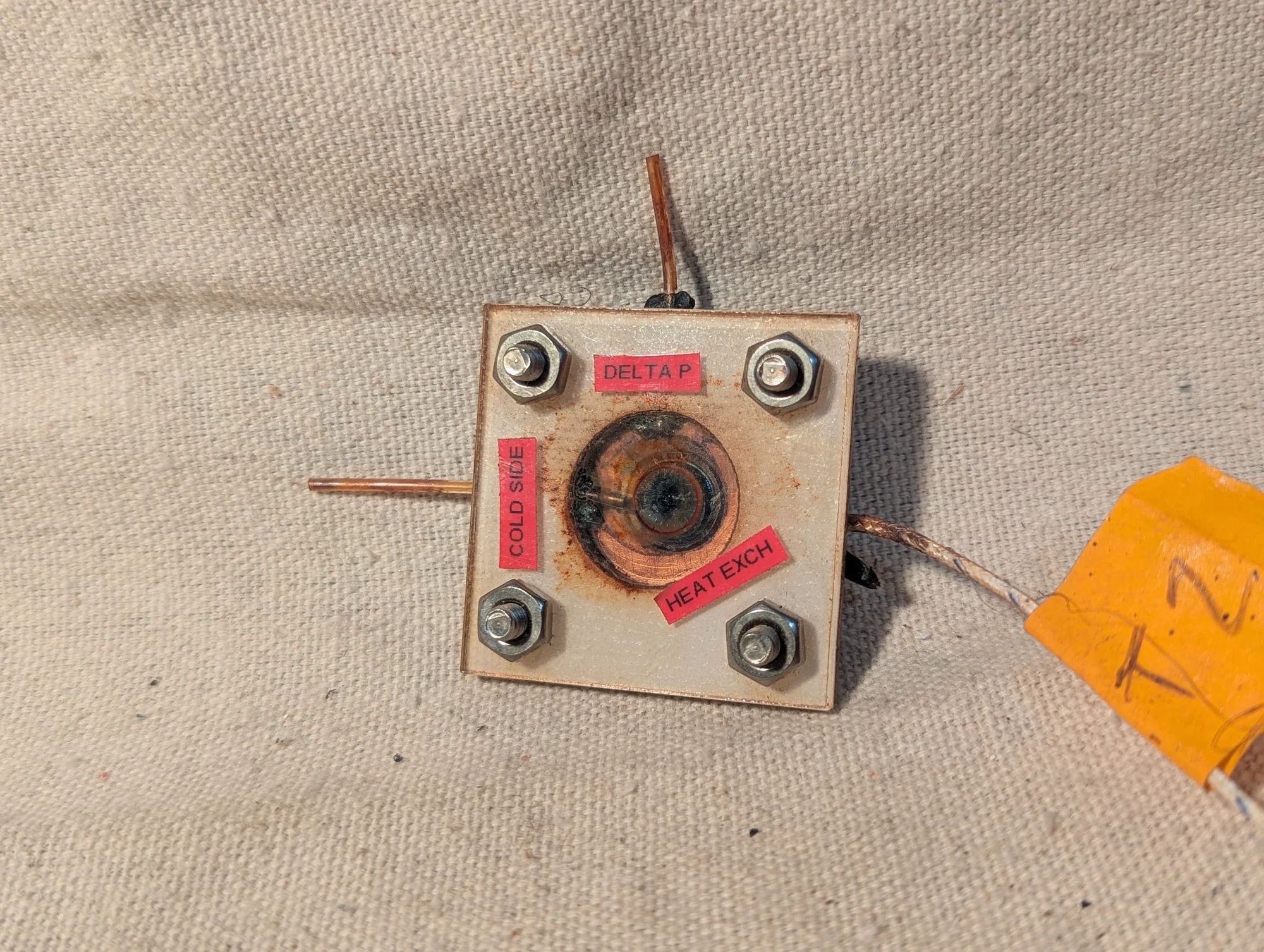
Another view of the chamber used to explore temperature differences and pressure-driven heat transfer in ferrofluid. The positions of the fluid connections were chosen to compare regions nearer to and farther from the strongest magnetic field.
Controls and signal isolation
Photos 165–167, 328–329, 339–340, 346
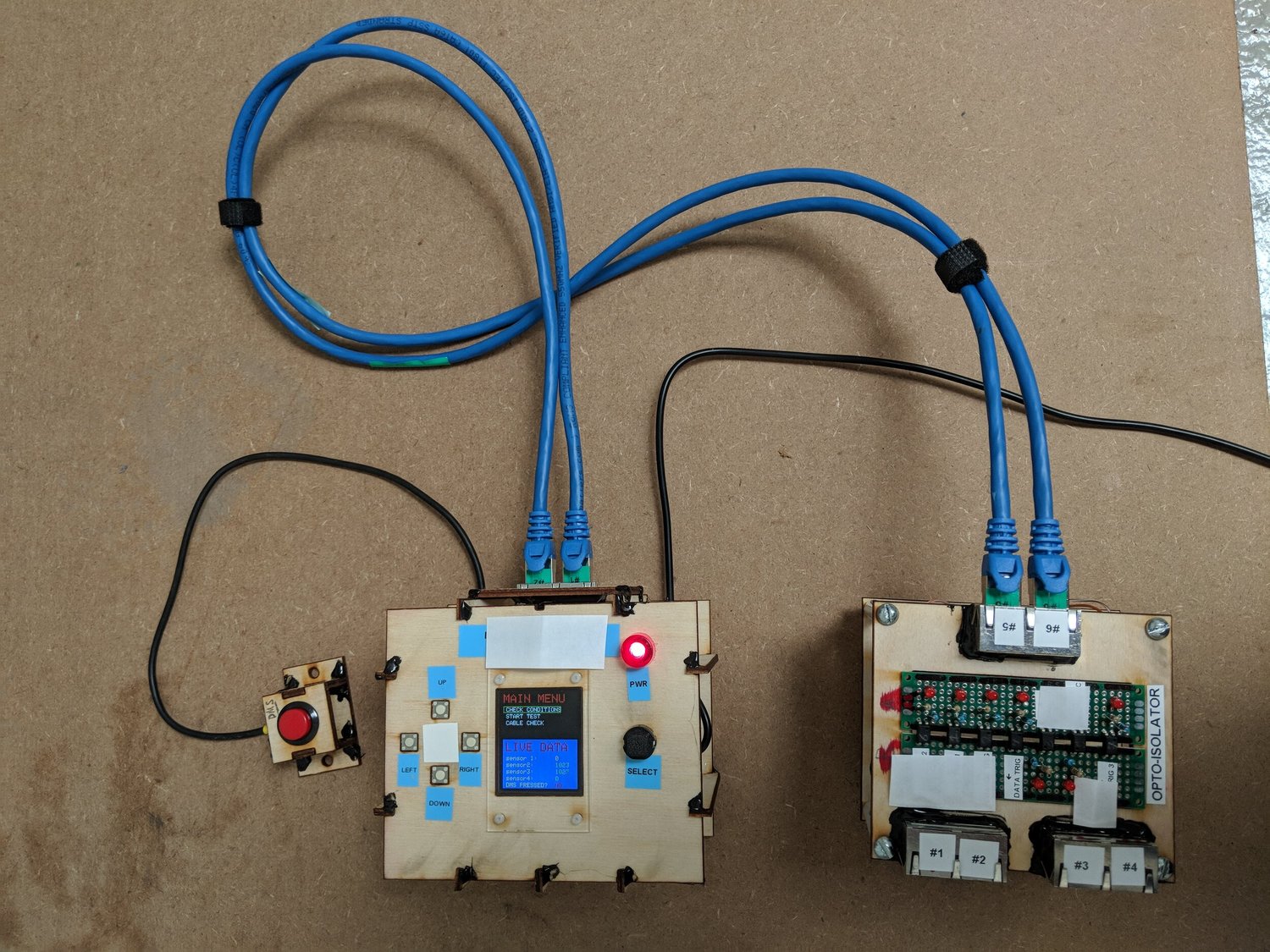
The small graphical interface used to select experimental programs and display feedback from the magnetic-refrigeration apparatus. Control signals passed through opto-isolators—components that transfer signals using light—to electrically separate the interface from other parts of the system.
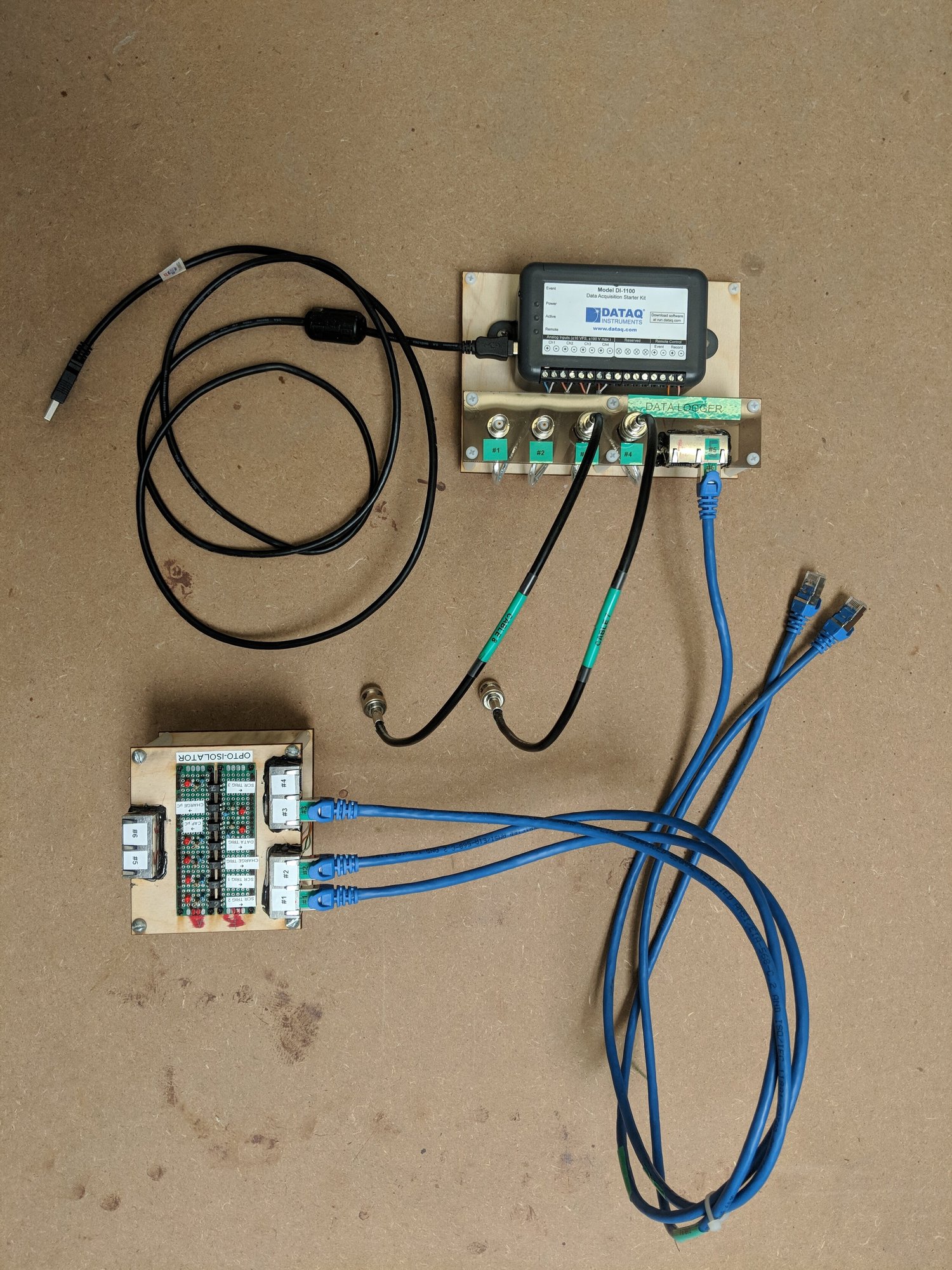
Data loggers used to record signals such as voltage and current during the magnetic-refrigeration experiments. A trigger connection provided a way to start recording at the relevant point in a test.
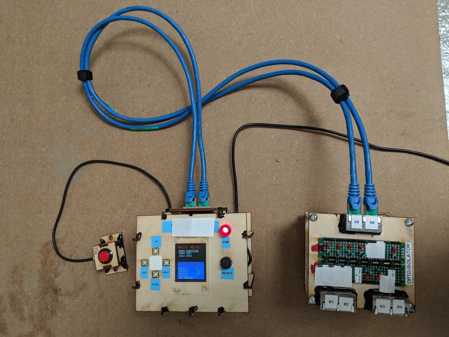
This is the same photograph as Photo 165, showing the magnetic-refrigeration control interface and its associated electronics. Both existing photo numbers are retained during the caption review.
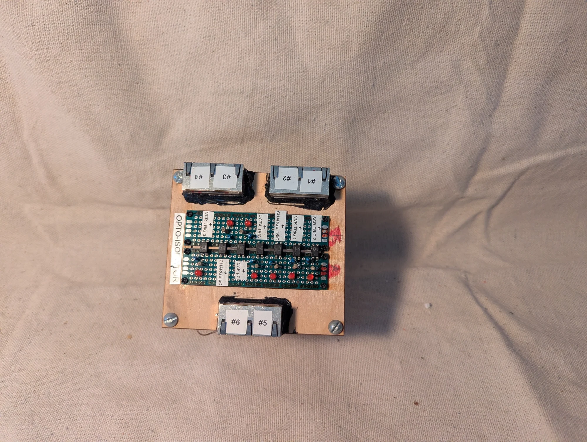
An optoisolator board I made for Fernbrake's magnetic-refrigeration project. Optoisolators pass signals using light, keeping the controller electrically separate from the high-power circuitry. I used network-style sockets because I had them on hand; they carried simple on/off control signals, with no Ethernet communication involved.
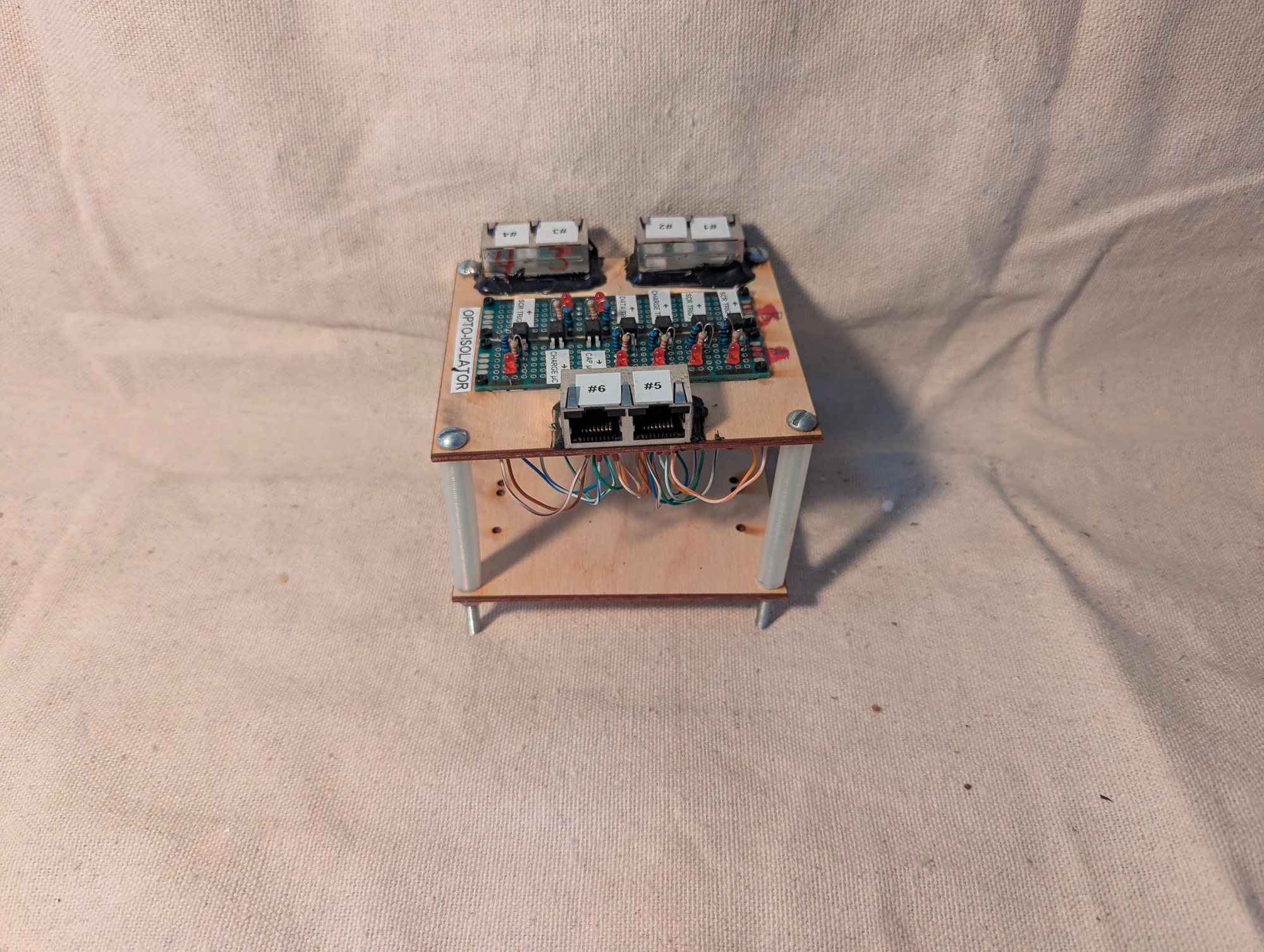
A second view of the optoisolator board and its connectors. Its role was to pass control signals between electrically separate sections of the magnetic-refrigeration apparatus.
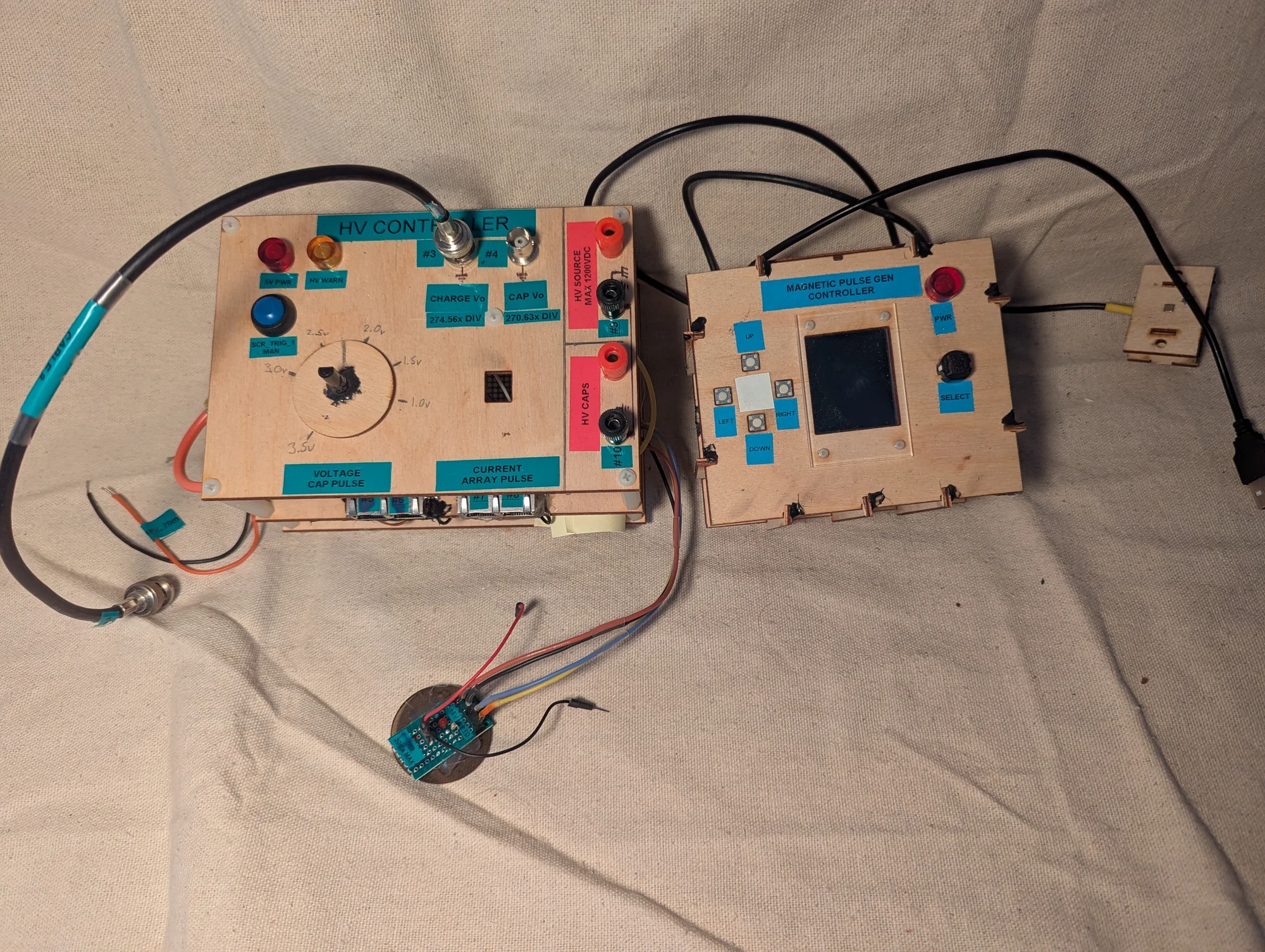
The right-hand box let me choose test programs, pulse patterns, charge/discharge timing, and target voltages. Its screen displayed settings and voltage feedback. The left-hand box managed capacitor charging. I monitored discharge current with a separate current transformer, but do not recall whether current also appeared on the controller's screen. Twisted-pair network cables carried the control connections.
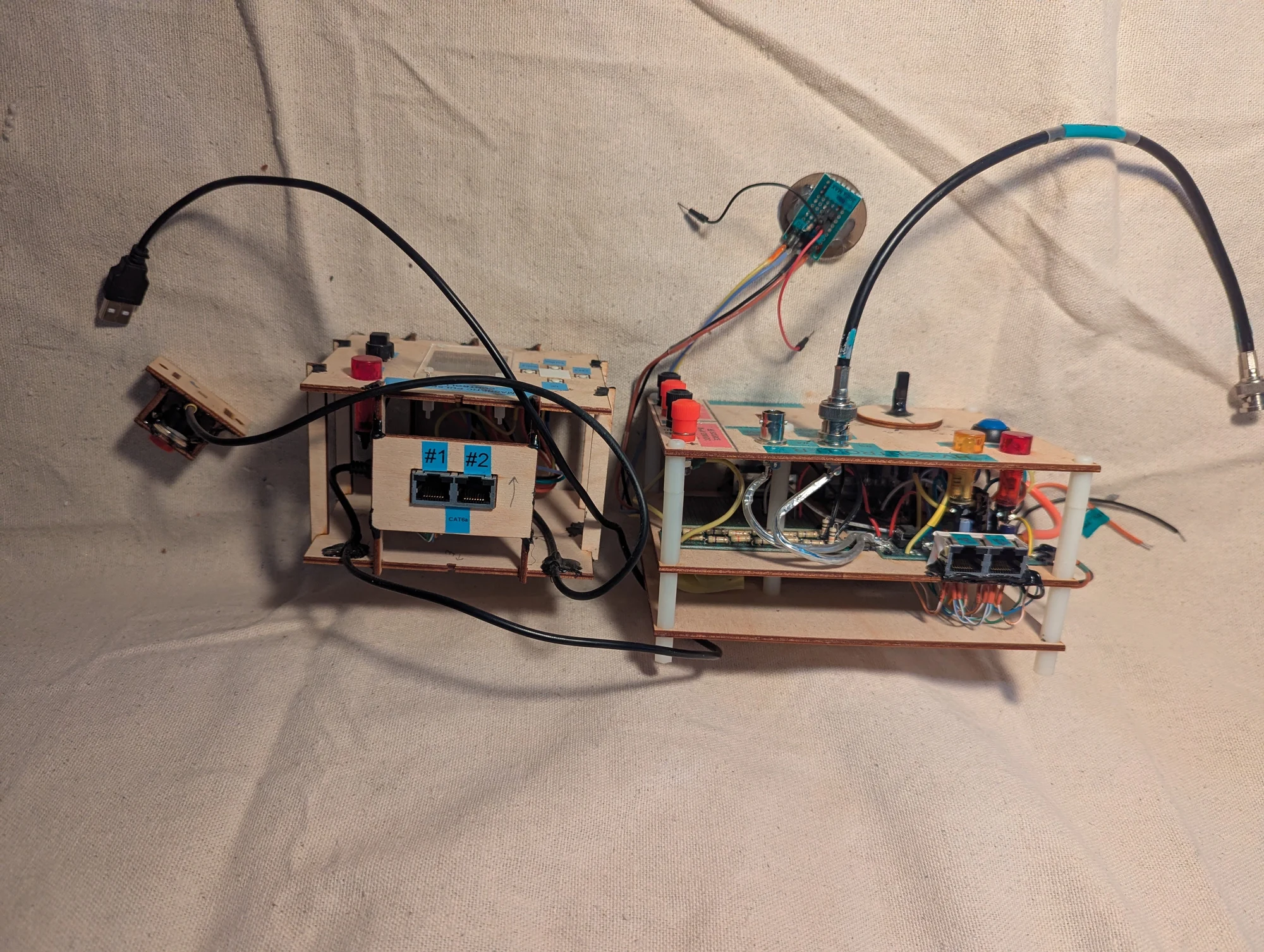
Another view of the magnetic-refrigeration controls, showing the user-interface box and the capacitor-charging controller. Network-style cables provided convenient control wiring between the assemblies; no Ethernet protocol was involved.
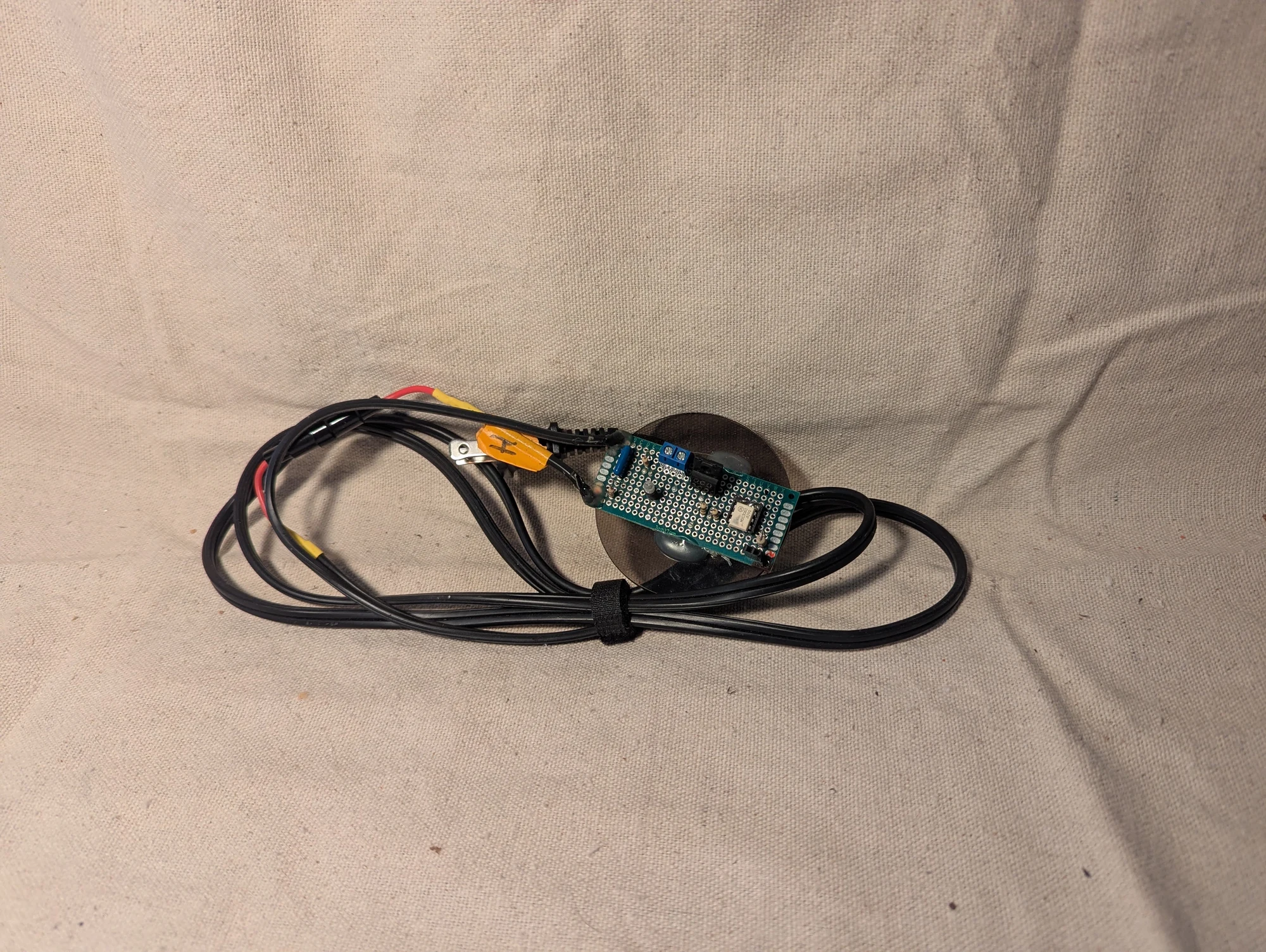
Another component of the capacitor-bank charging controller used in the magnetic-refrigeration project.
Gadolinium and pulsed-field apparatus
Photos 330–338
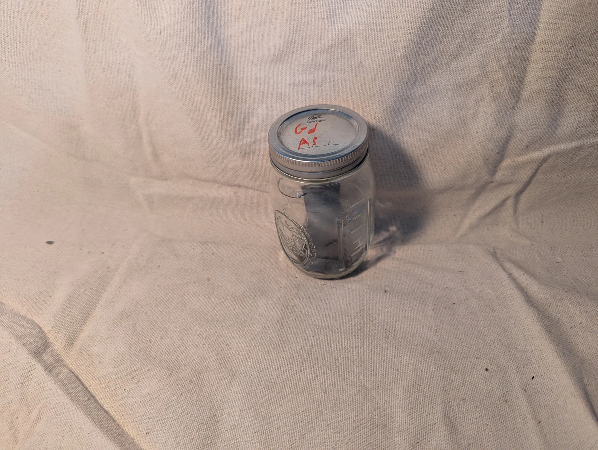
Gadolinium sheets stored in an argon atmosphere. I purchased a batch of this material for Fernbrake's magnetic-refrigeration experiments.
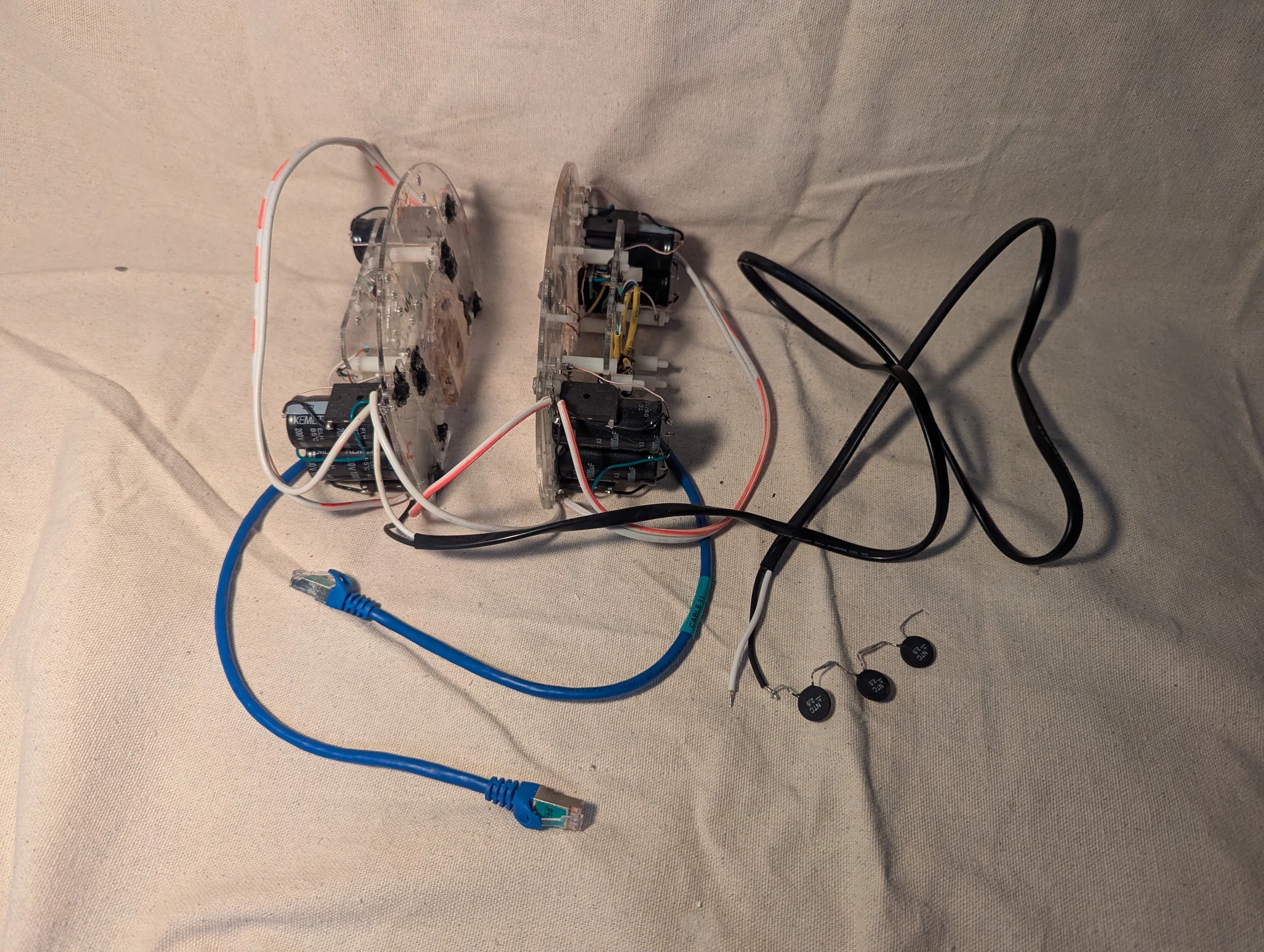
An experimental assembly from my Fernbrake magnetic-refrigeration work. Flat coils of litz wire sat on either side of a gadolinium sheet, with capacitor banks supplying brief bursts of electrical energy. I was exploring the magnetocaloric effect, a change in a material's temperature associated with a changing magnetic field. I later questioned whether magnetic losses and limited heat transfer would make this approach practical.
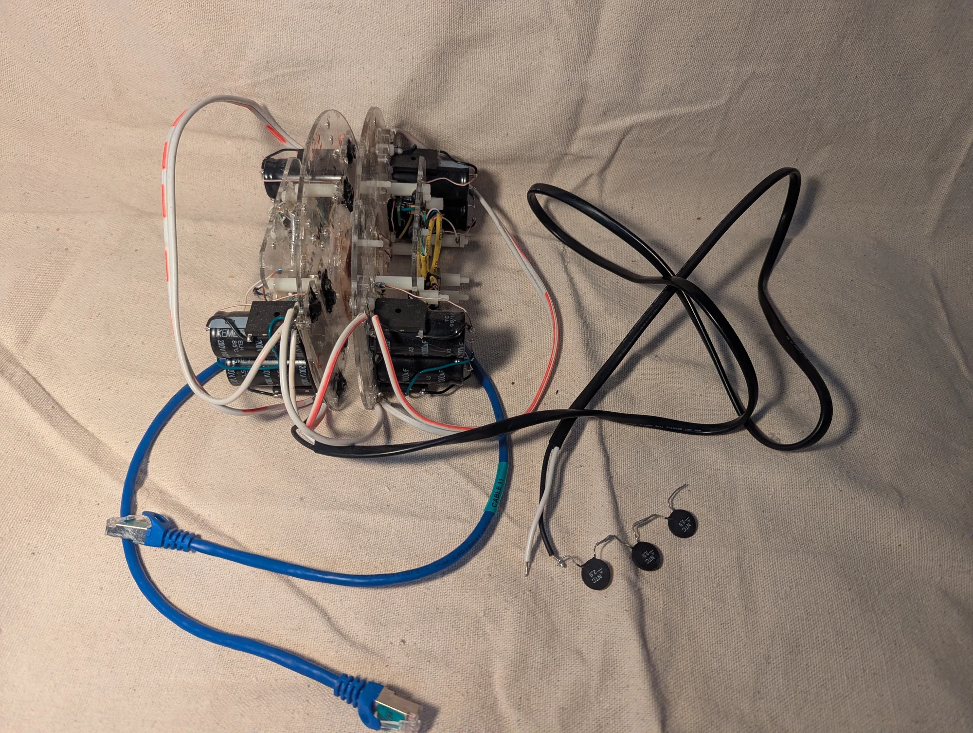
The two sides of the pulsed-field assembly positioned around the central plates. The experiment was intended to expose the gadolinium to brief magnetic-field changes as part of the cooling research.
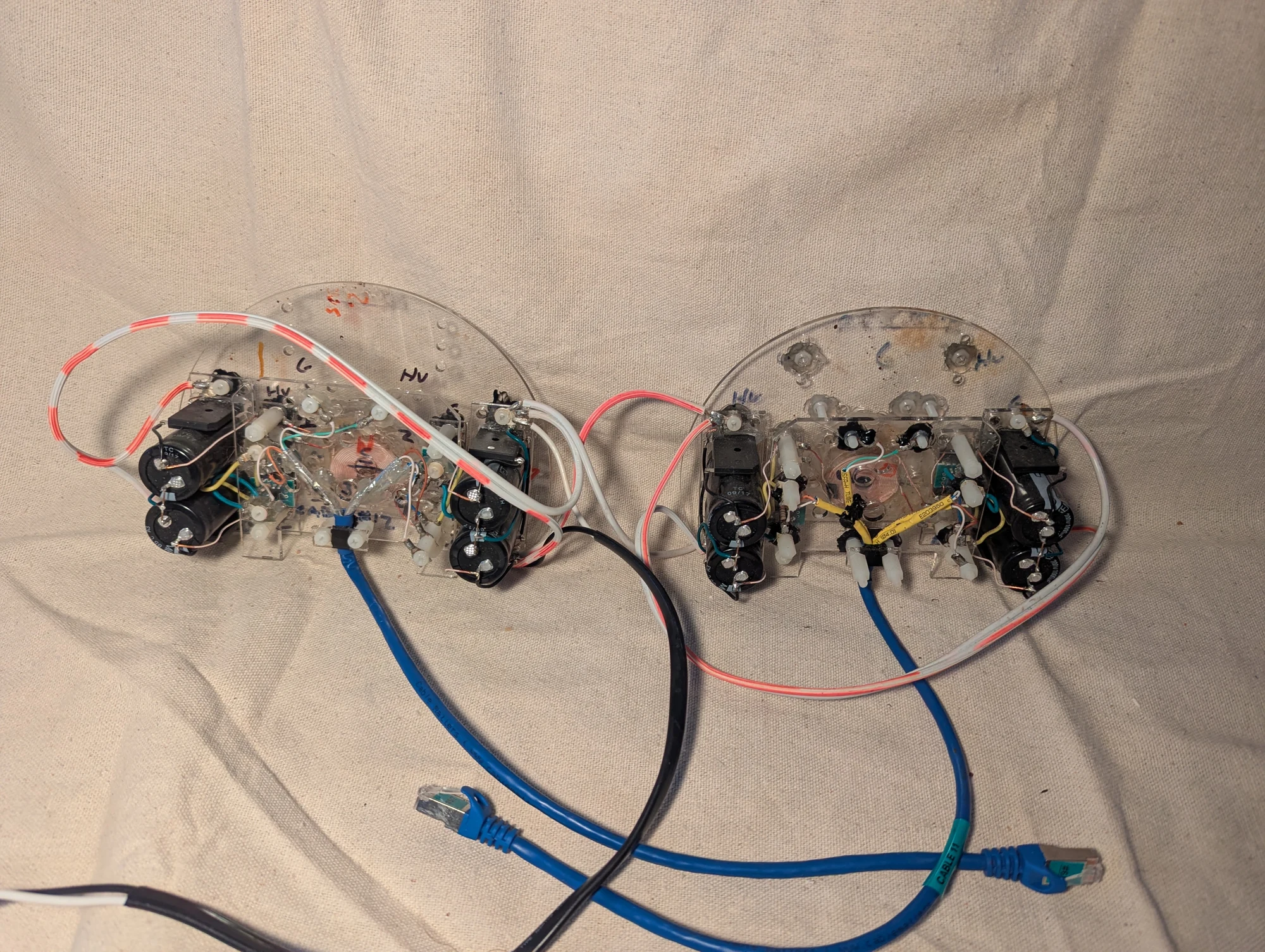
The assembly opened to show the flat litz-wire coils in the center and the capacitor banks beside them. Network-style cables provided convenient connections for the triggering controls; they were used as ordinary control wiring.
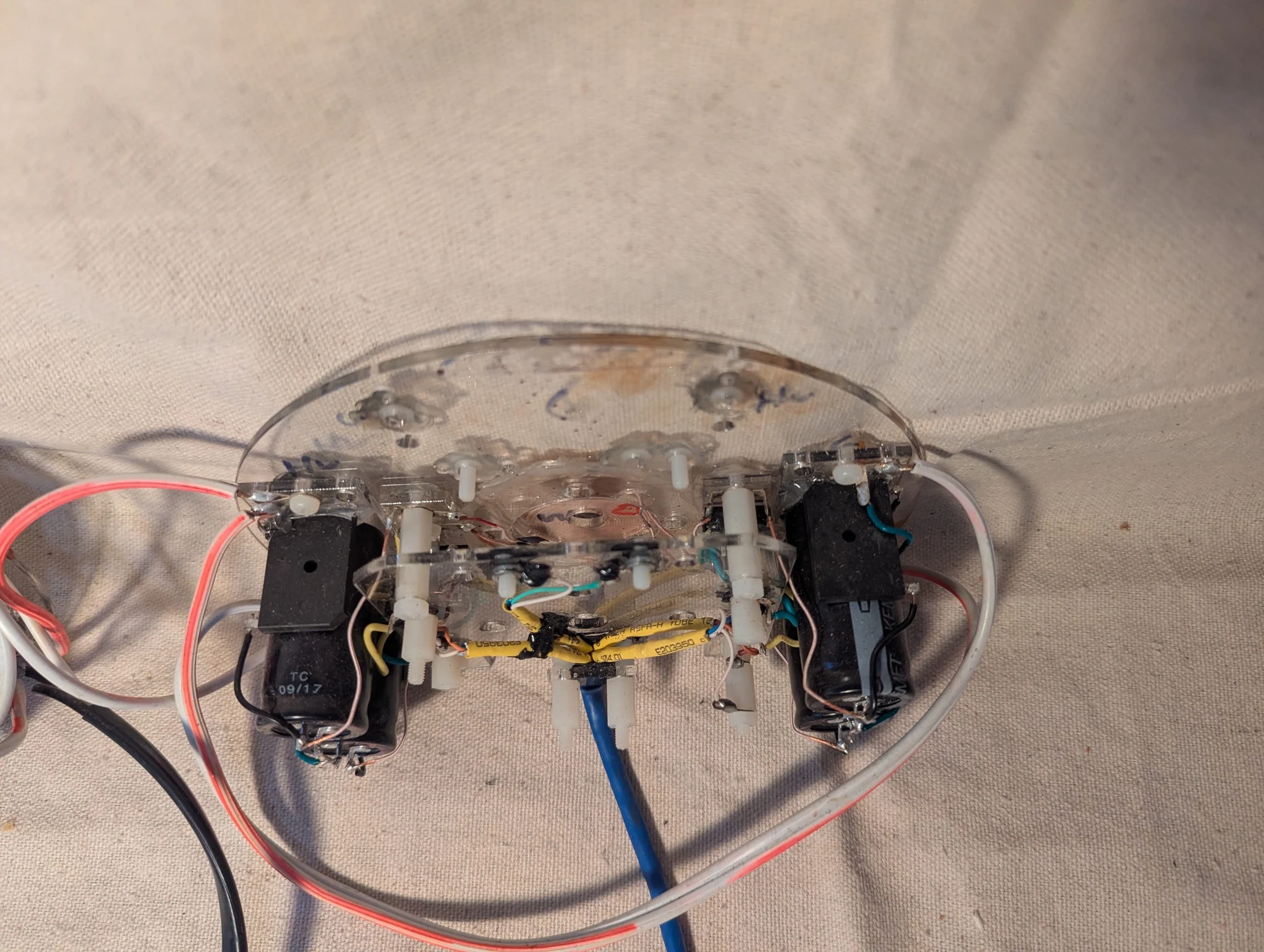
Another view of one half of the magnetic-refrigeration experiment, showing the central coil and the surrounding electrical components.
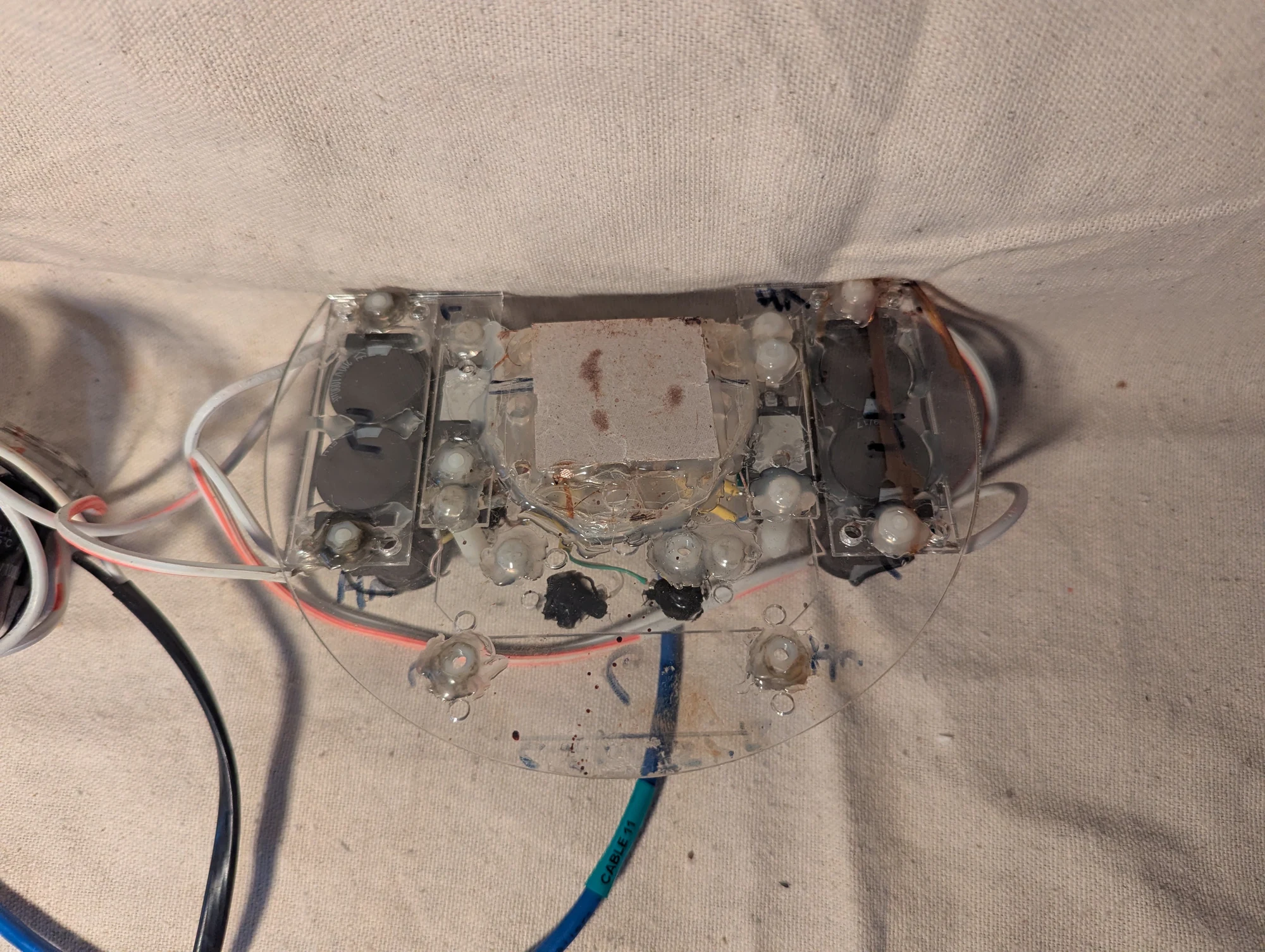
A close view of a thin insulating sheet in front of the flat coil. I recall this sheet being mica, used to provide a thin, nonmagnetic insulating surface.
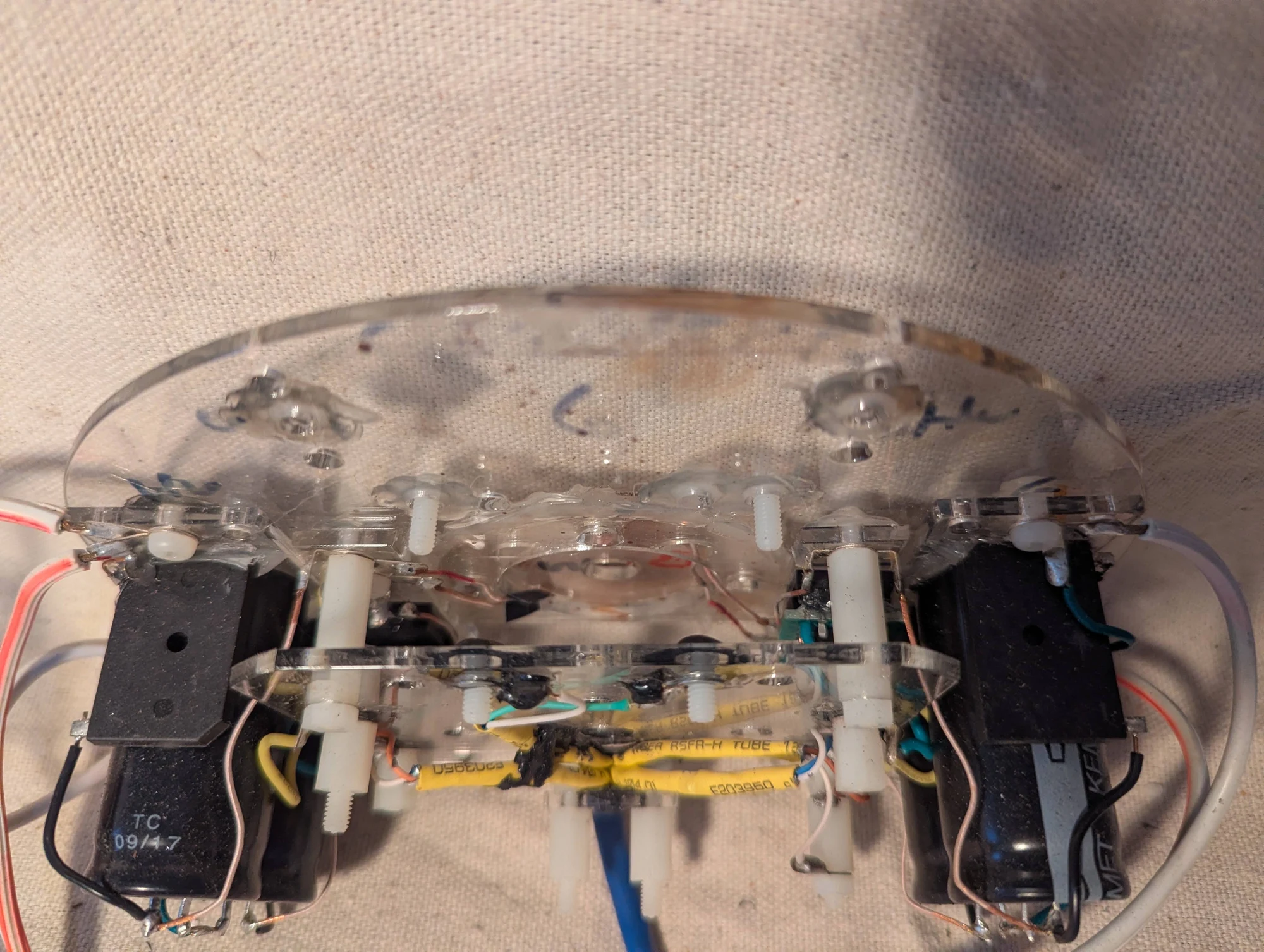
Another angle on the pulsed-field assembly, with the coil, insulating layer, and surrounding components visible.
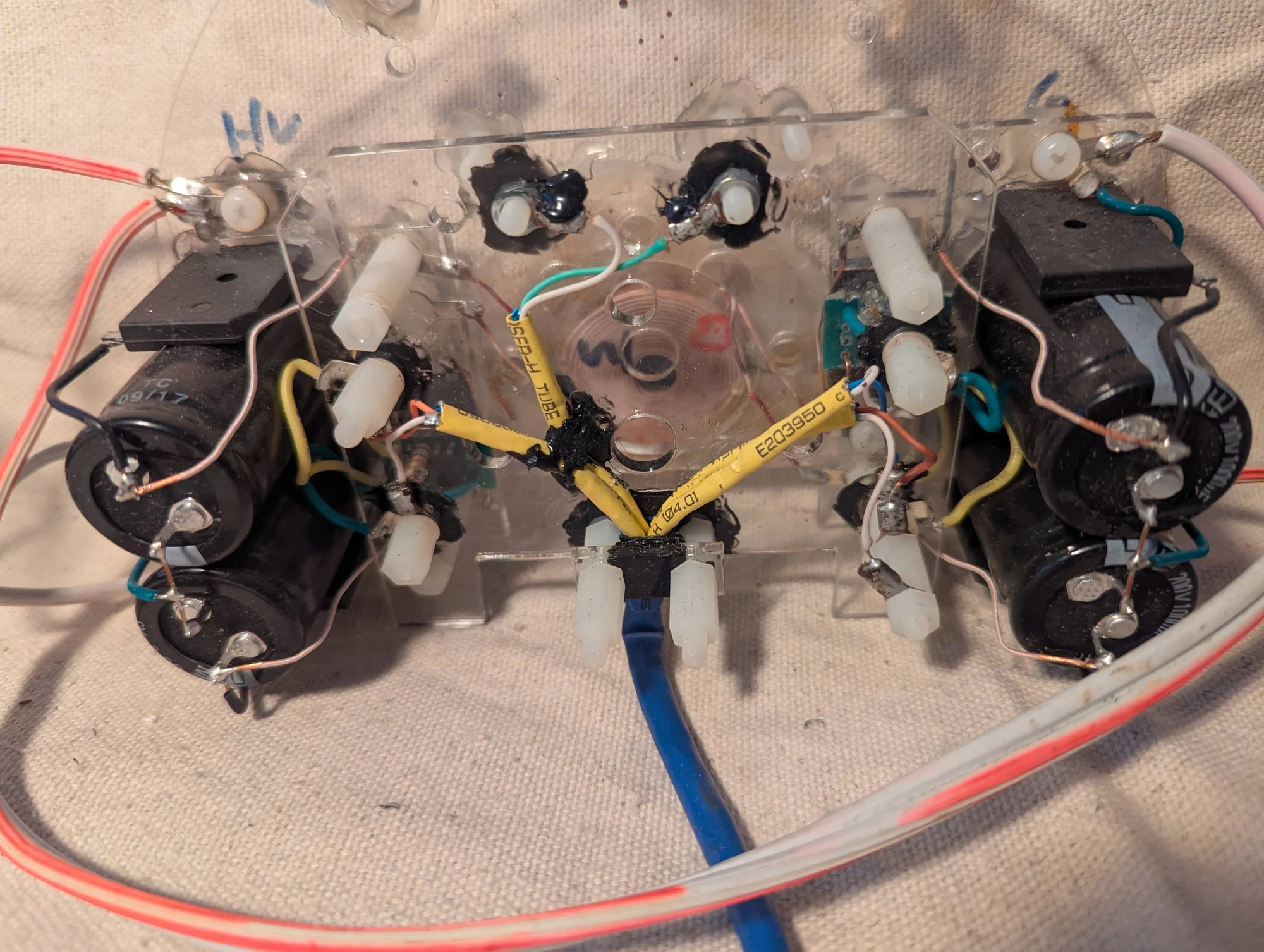
A closer view of the central region of the magnetic-refrigeration apparatus and its surrounding wiring and components.
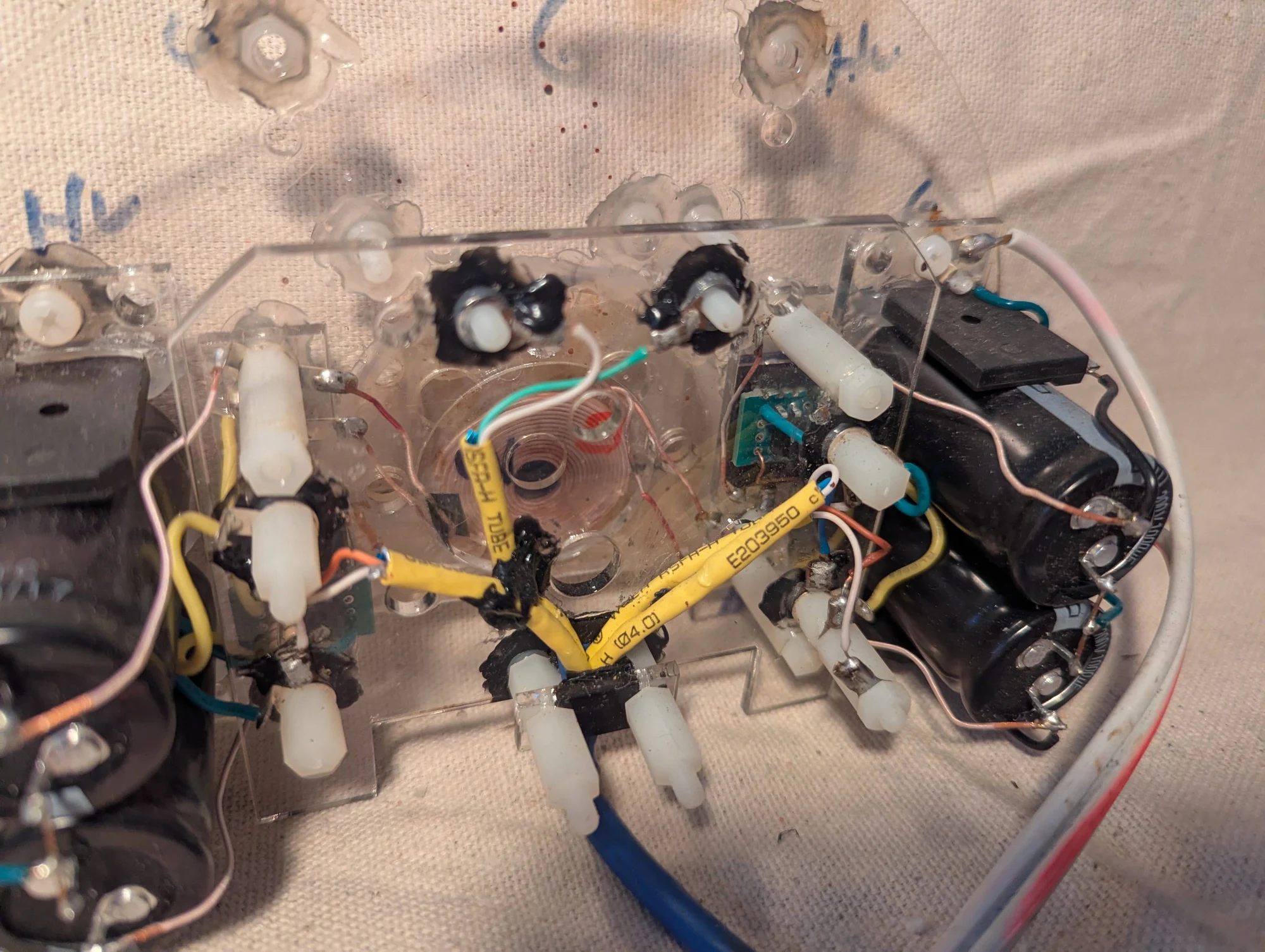
An additional view of the pulsed-field apparatus used in the exploratory magnetic-refrigeration work.
Fluid and temperature-gradient experiments
Photos 341–342, 347, 374–376, 390–391
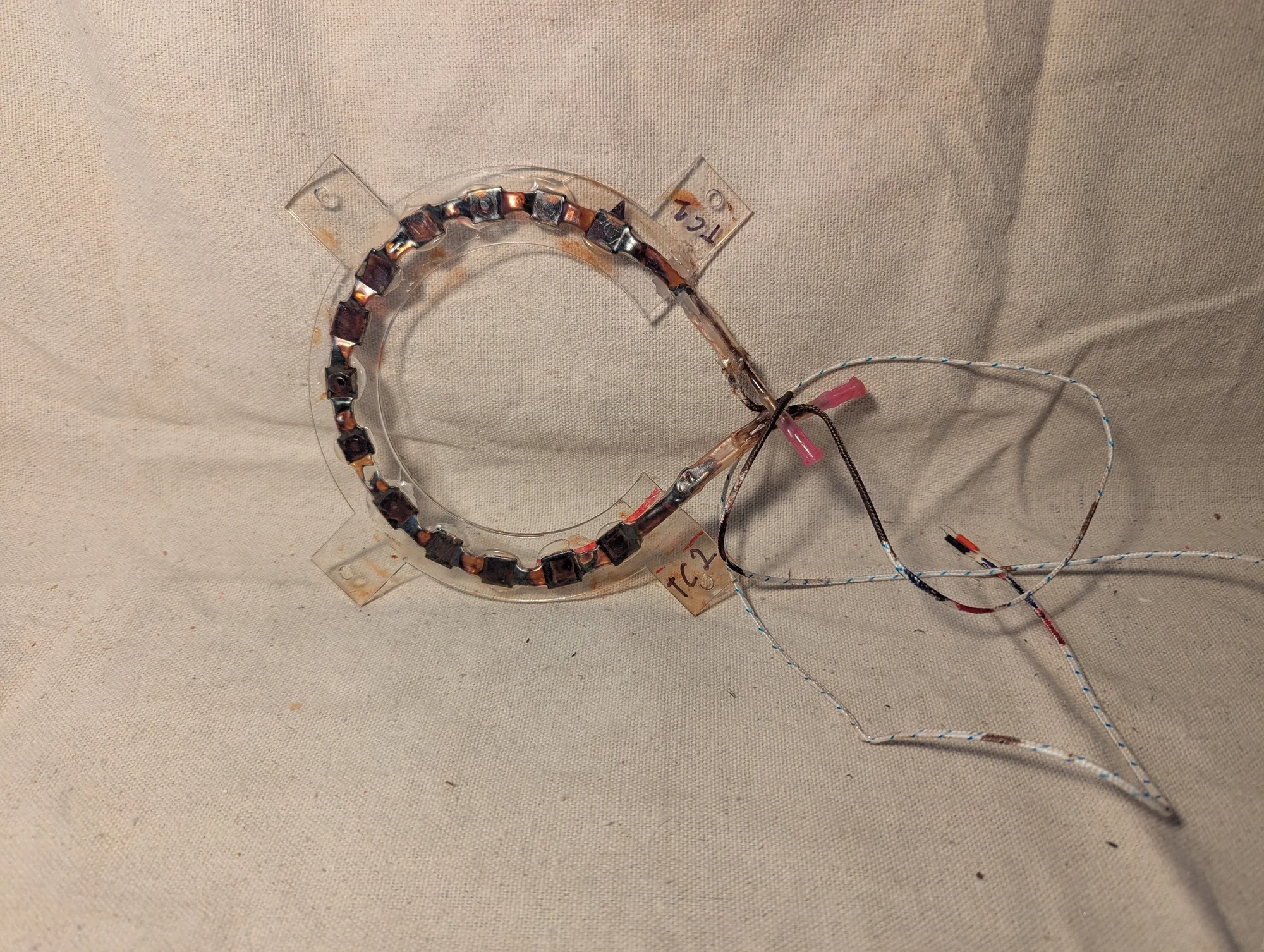
A crescent-shaped tube holding gadolinium pieces and ferrofluid, with thermocouples to track temperature and syringe tips for filling. I was investigating a cooling concept in which a rotating magnet would preferentially attract cooler ferrofluid and displace warmer fluid. Repeating that motion was intended to build a hot-to-cold temperature difference along the arc.
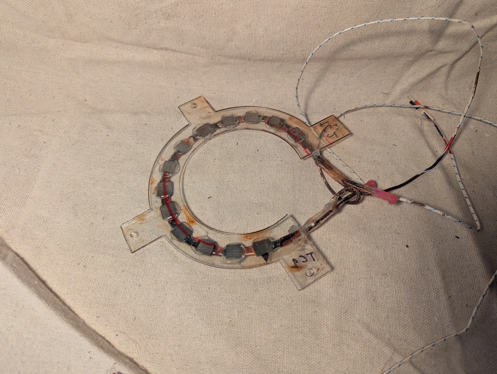
A second angle on the gadolinium-and-ferrofluid assembly. The concept explored whether temperature-dependent magnetic attraction could redistribute the fluid to create warmer and cooler ends of the arc. Thermocouples were attached to measure temperature changes.
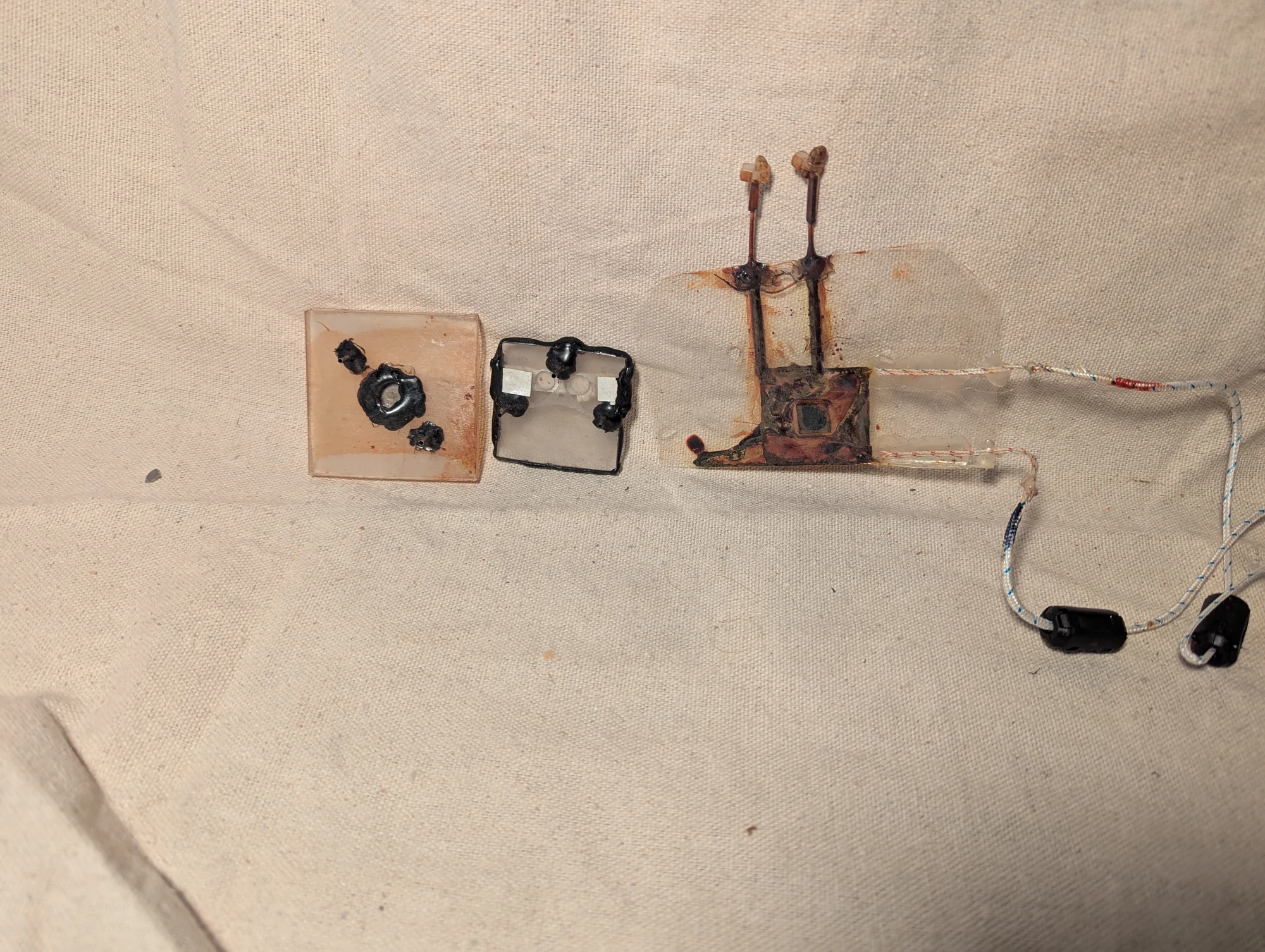
An experimental chamber made from two laminated sheets, with gadolinium inside. I used it to explore whether magnetic attraction could create a temperature gradient in ferrofluid.
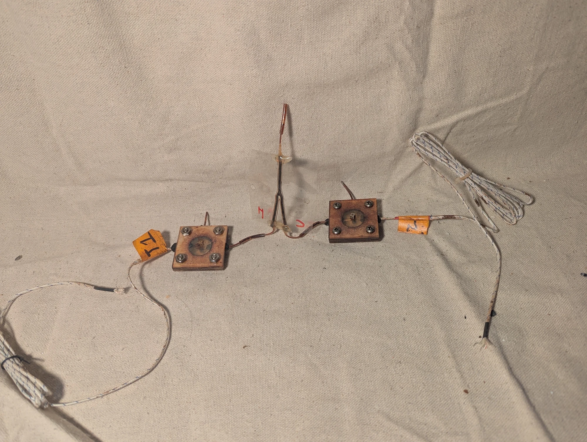
An experiment to test whether warmer and cooler ferrofluid would separate near a magnet. I introduced a mixture of the two into the tube, then positioned one thermocouple near the magnet and another a few millimeters farther away. I recorded and graphed the temperatures to look for a difference between the regions.
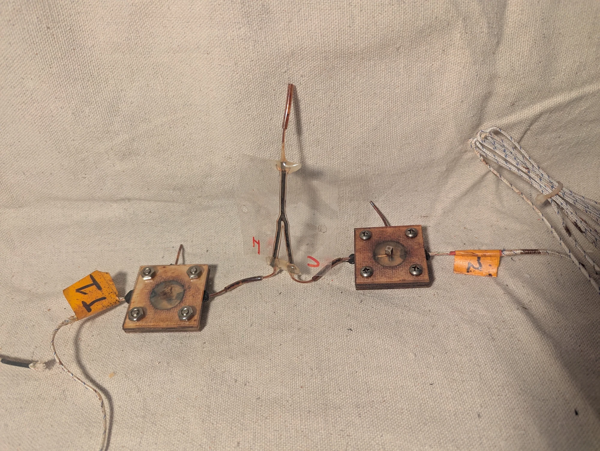
Another view of the ferrofluid experiment in Photo 374. Temperature probes near the magnet and just outside that region let me compare where cooler and warmer fluid might collect. A data logger recorded the readings for plotting.
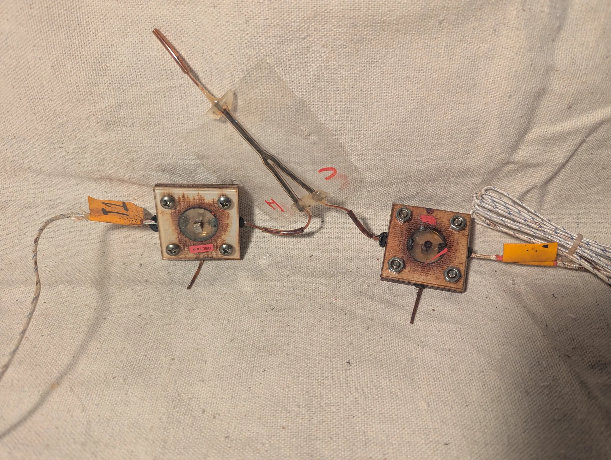
A closer view of the setup used to investigate temperature differences in ferrofluid near a magnet. The experiment compared two nearby locations after introducing warmer and cooler fluid into the chamber.
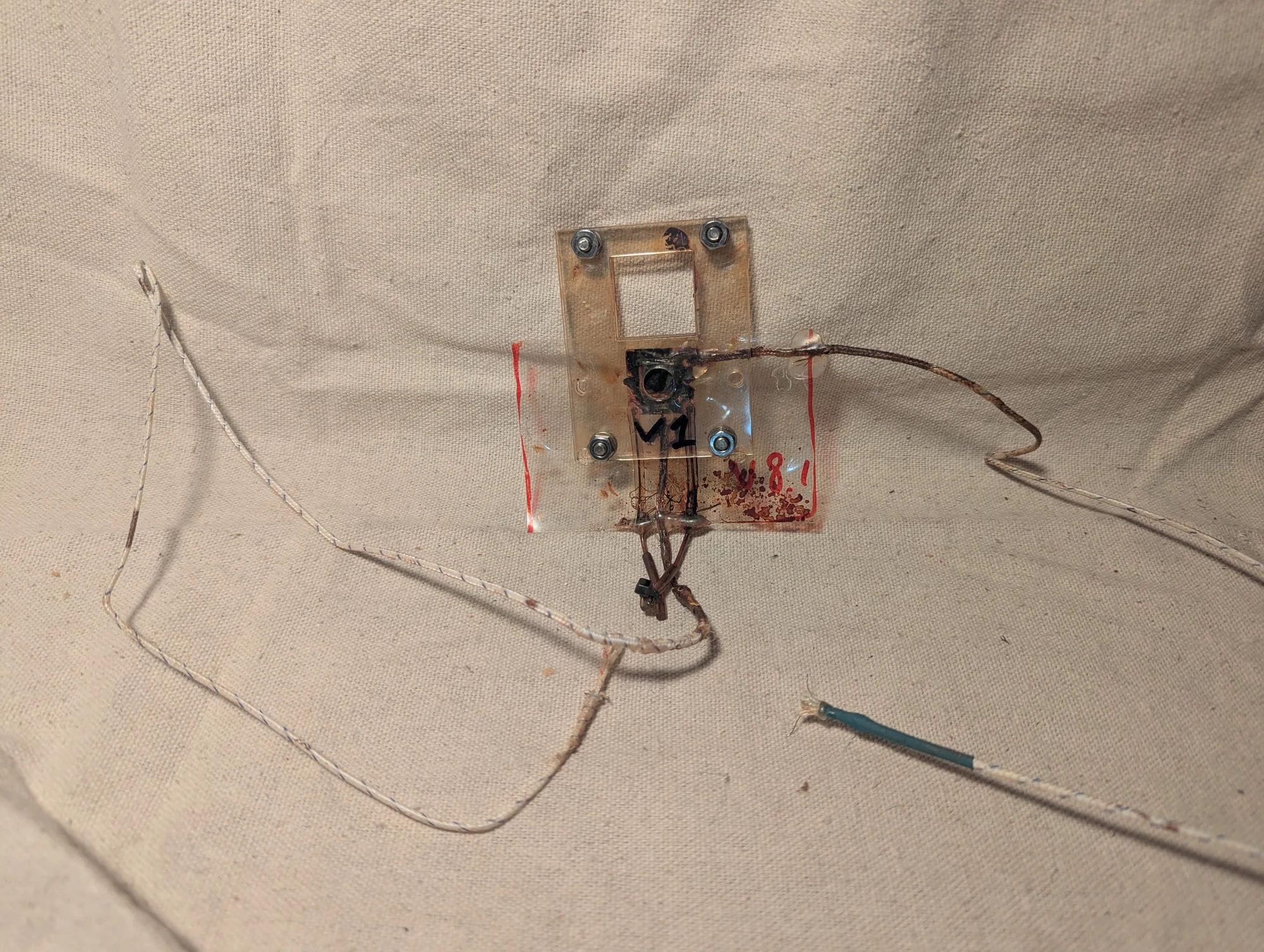
A small gadolinium square held in a pocket of ferrofluid, with thermocouples attached. I used this arrangement to look for temperature changes when the sample was exposed to a magnetic field, as part of my experiments with magnetic refrigeration.
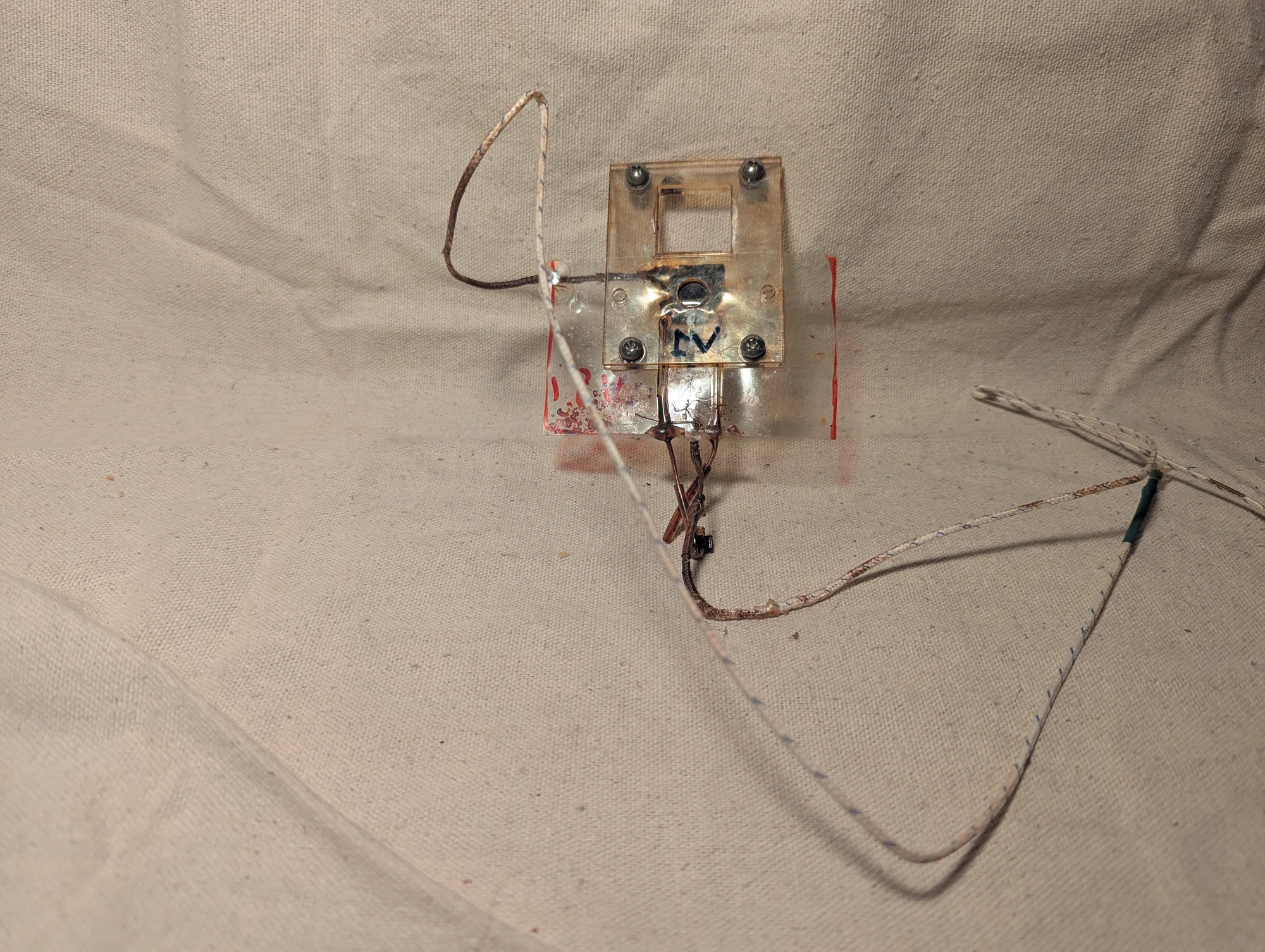
An alternate view of the gadolinium-and-ferrofluid test chamber. The attached temperature probes were intended to help measure the sample’s response to an applied magnetic field.
Heat-exchanger trials
Photos 411–414
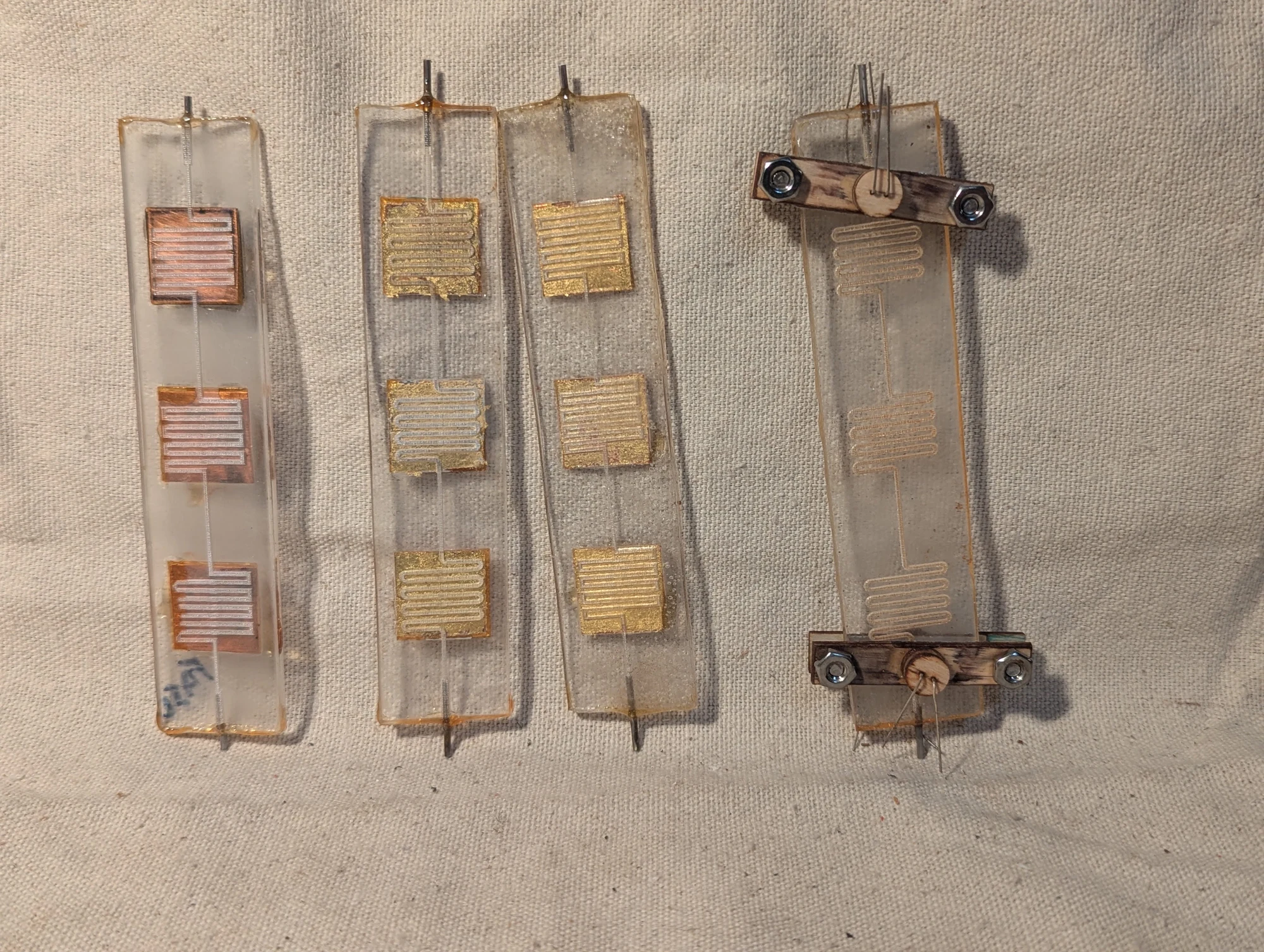
Microfluidic heat-exchanger prototypes with metal plates embedded in acrylic. Serpentine channels guided the fluid across copper surfaces before it left the device. Some plates were covered with gold foil in an effort to reduce chemical interaction with the fluid. The collection also includes an earlier test assembly.
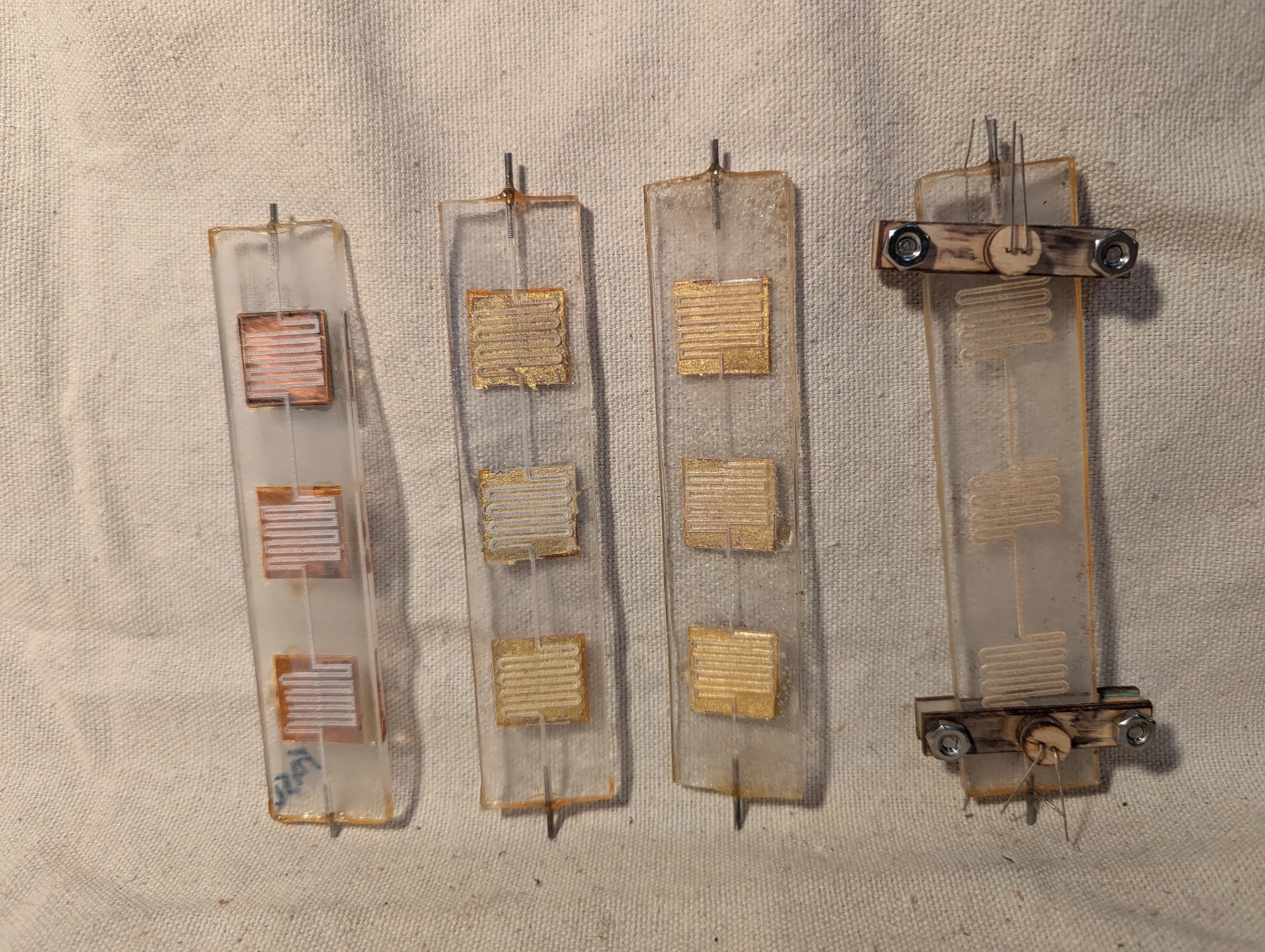
Another view of the acrylic heat-exchanger prototypes. The winding channels were intended to keep fluid in contact with the embedded metal surfaces along a longer path, allowing me to explore controlled heat transfer on a small scale.
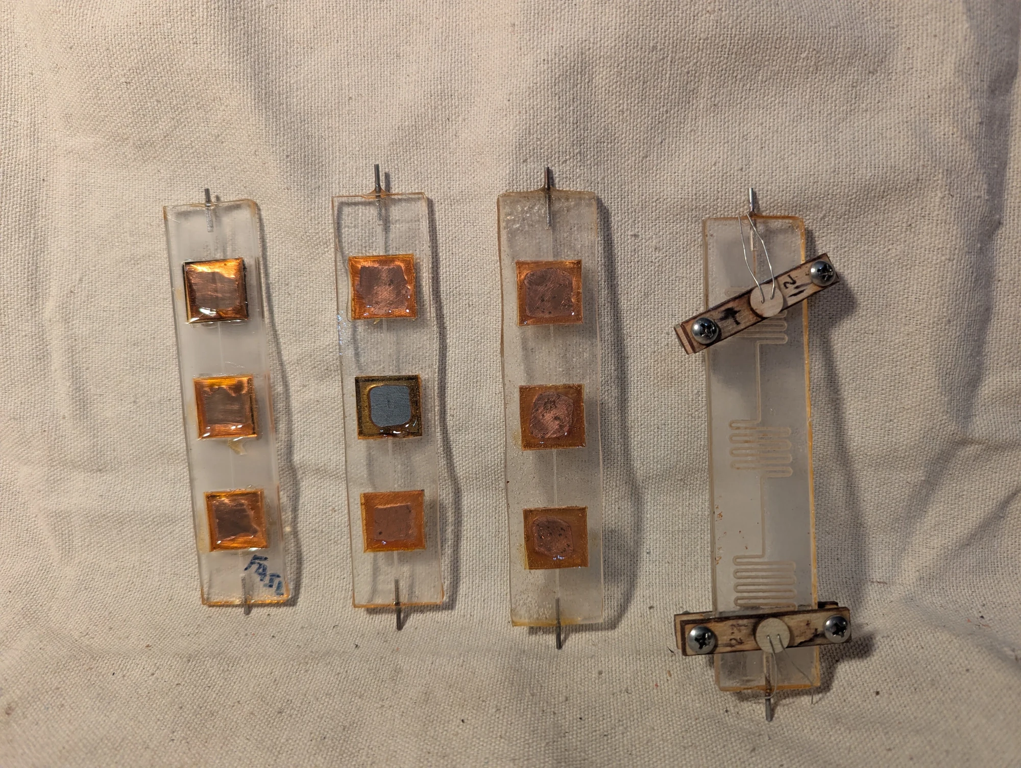
A further view of the heat-exchanger collection, showing several plate and channel arrangements. I used these experimental assemblies to explore moving heat between ferrofluid and metal surfaces, with different paths guiding the fluid across the plates.
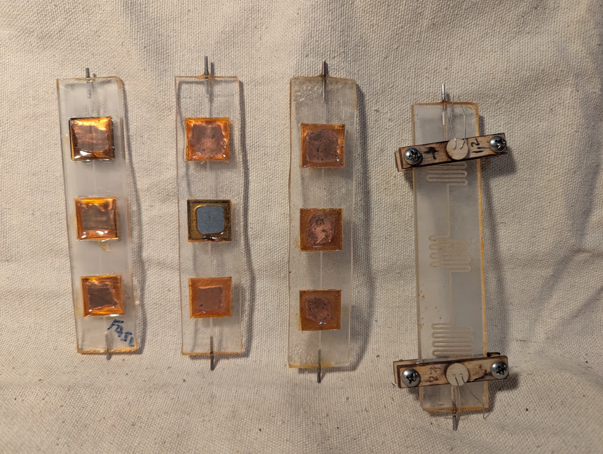
Another view of the heat-exchanger experiments. One version may have used a gadolinium plate between copper plates: the idea was to expose the gadolinium to a magnetic field, then move the fluid above it toward either copper plate and measure the temperature change. Looking back, I suspect the copper’s mass was too large for such a small amount of ferrofluid to produce a measurable temperature change.