PHOTO CAPTION REVIEW
Personal & contract photos
Every original photo, with its permanent number.
Use this grid to revisit descriptions or refer to a photo by number. Open its project link to see related photographs together.
Photo numbers stay unchanged when duplicates are removed. Numbers 201–202 are reserved for other material. Your later photos, 246–521, remain in Additional projects.
236 project photographs · select a photo to enlarge
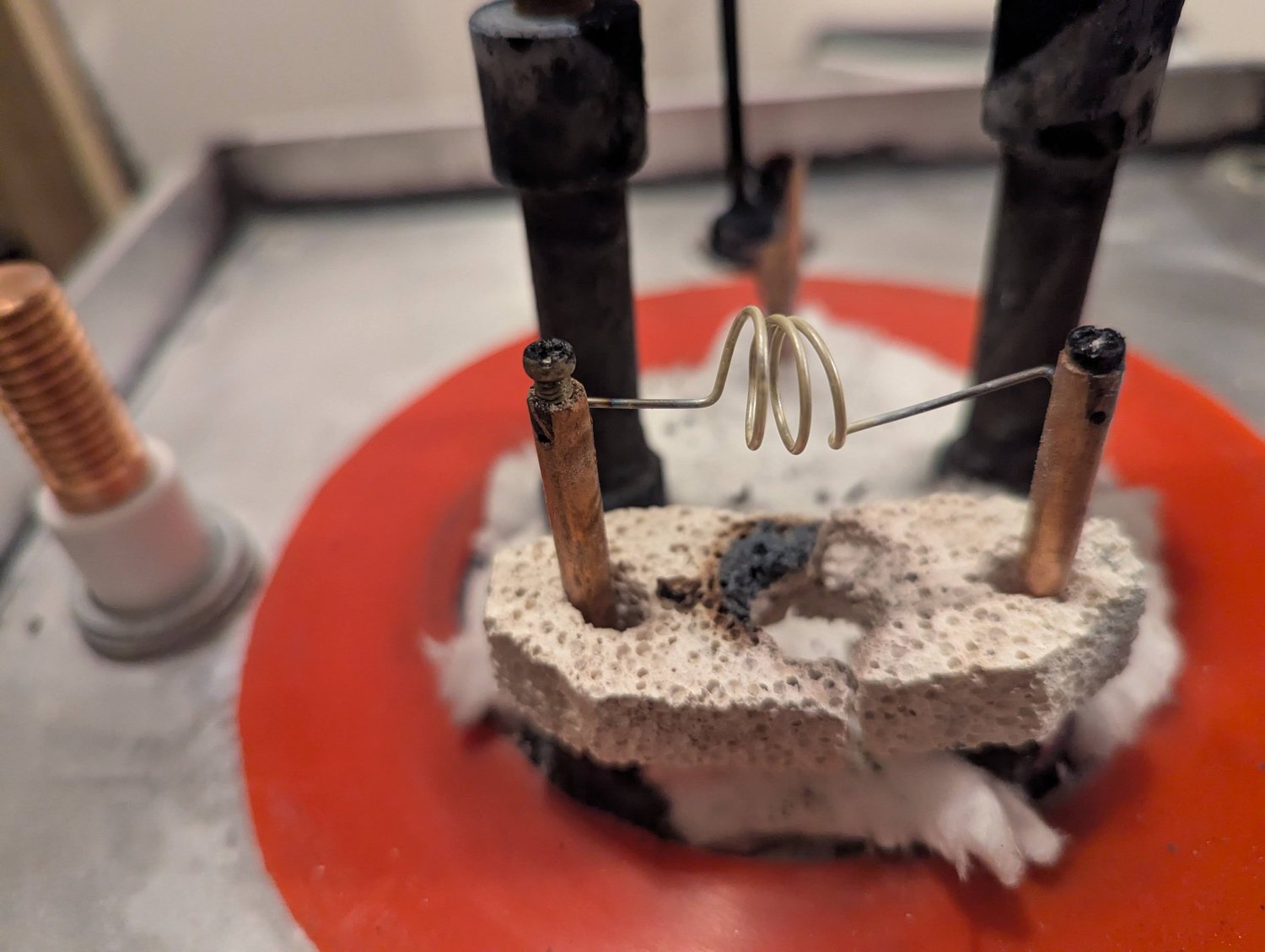
Personal project
Tungsten oxidation testsTitanium wire to capture oxygenA titanium-wire getter inside the stainless steel ‘noodle pot’ furnace. A getter is a sacrificial material that captures unwanted gas: here, the heated titanium reacts with oxygen and holds it as an oxide. I used it to reduce the oxygen available to attack the hot tungsten filament.
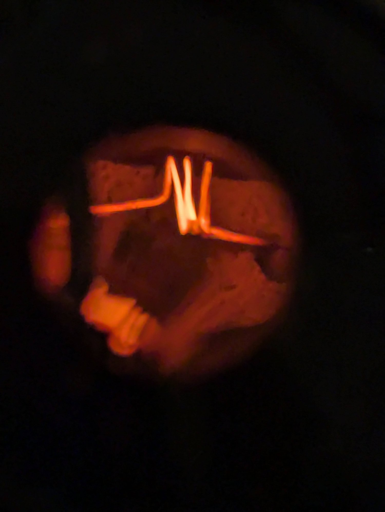
Personal project
Tungsten oxidation testsThe wire getter heating upThe titanium wire glowing as it heats up. This version used solid wire; in later experiments I used porous titanium sponge around a central nichrome heating coil. The sponge offered much more surface area and seemed to work better in my tests.
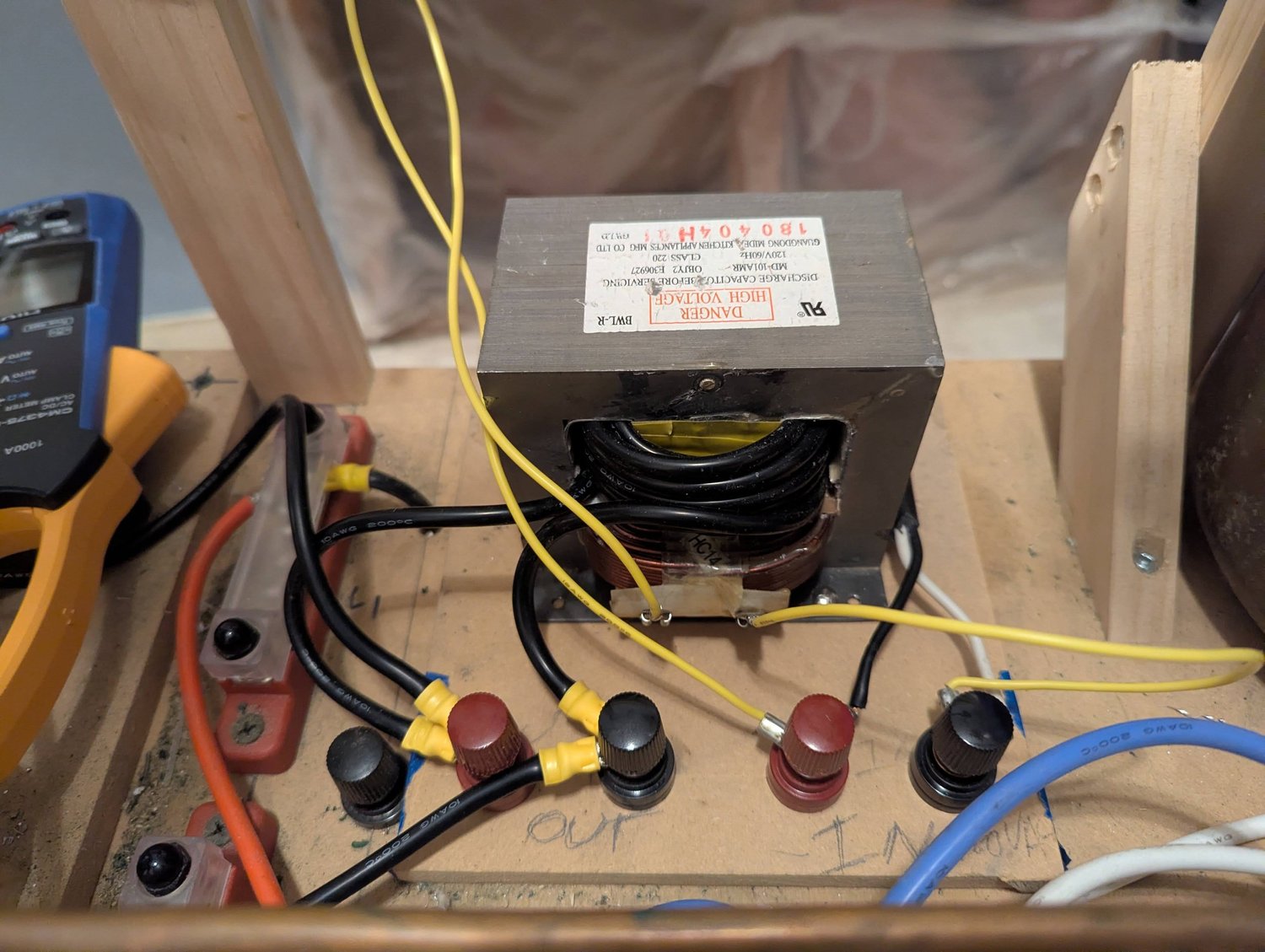
Personal project
Tungsten oxidation testsPower for the getterThe power supply for the titanium getter. It delivers a large electric current at a low voltage to heat the titanium wire, helping it capture oxygen inside the furnace chamber.
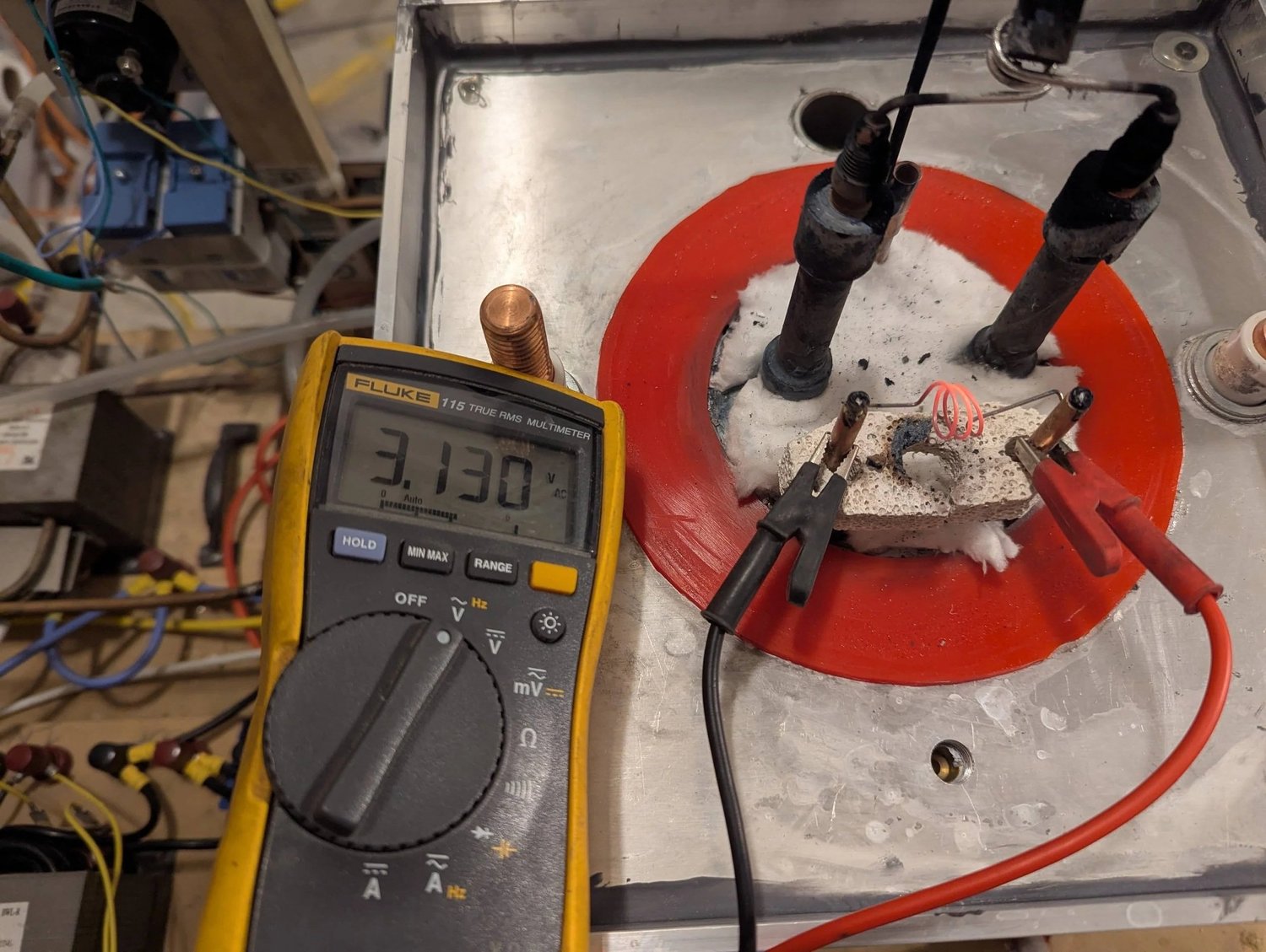
Personal project
Tungsten oxidation testsMeasuring voltage across the getterA voltage measurement across the titanium getter during testing. This was part of checking the electrical conditions used to heat the wire.
Personal project
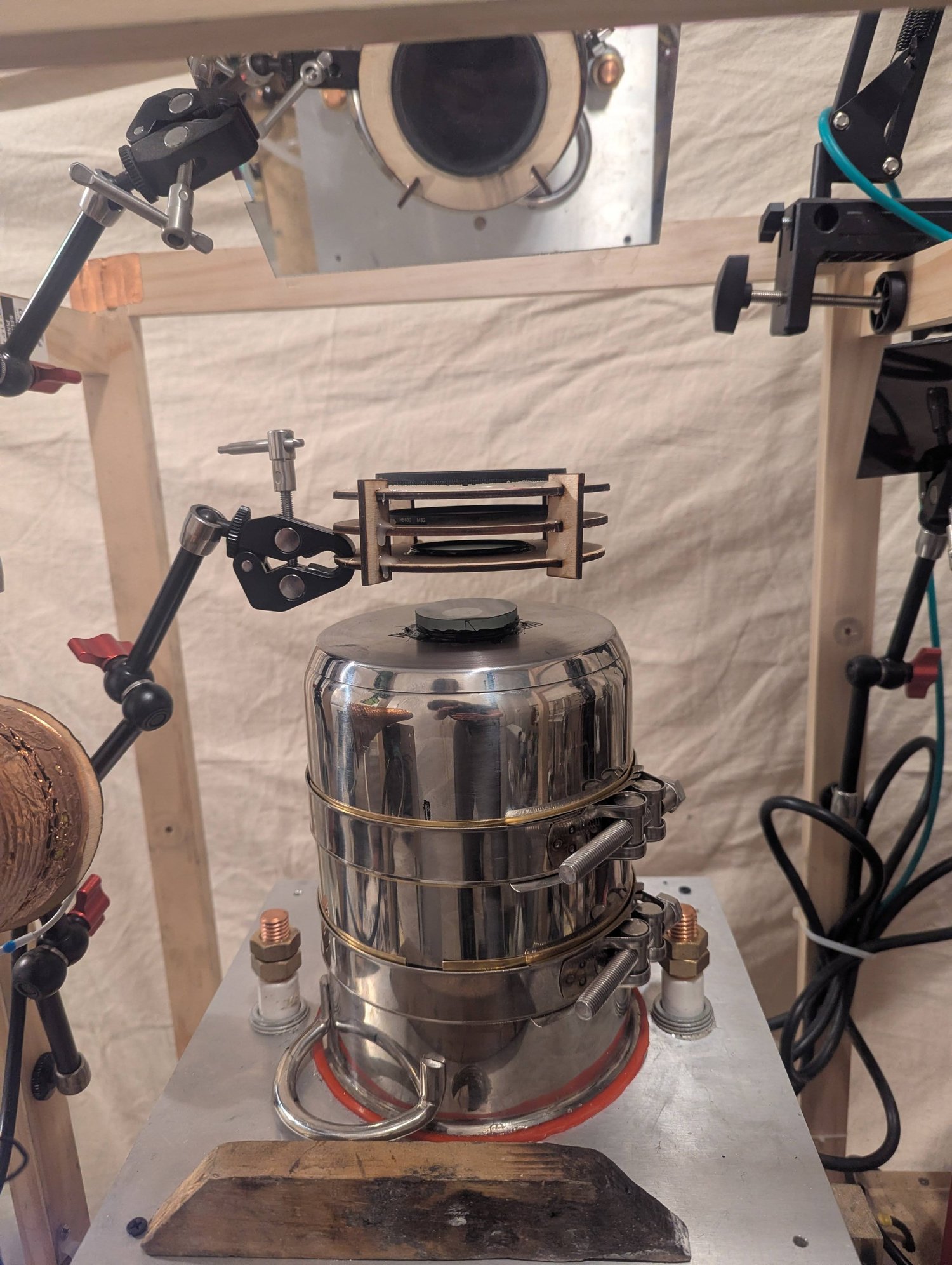
Noodle-pot vacuum furnaceA cooking pot becomes a furnace chamberI chose this stainless steel cooking pot because its width and height fit the furnace’s filament posts. I later abandoned this cooling arrangement: if the bottom silicone seal failed, the vacuum could draw cooling water into the hot chamber and damage the tungsten and other heated parts. That possible failure drove the redesign.
Personal project
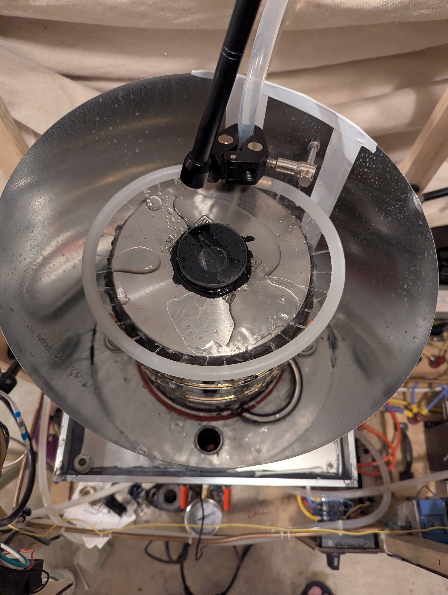
Noodle-pot vacuum furnaceSpray cooling and stiffening ringsA top view of the ‘noodle pot’ chamber, including the sprinkler that sprayed cooling water onto its steel walls. I added rings around the pot to help resist inward collapse or oval distortion under vacuum. They were a precaution; I did not establish how much support they provided.
Personal project
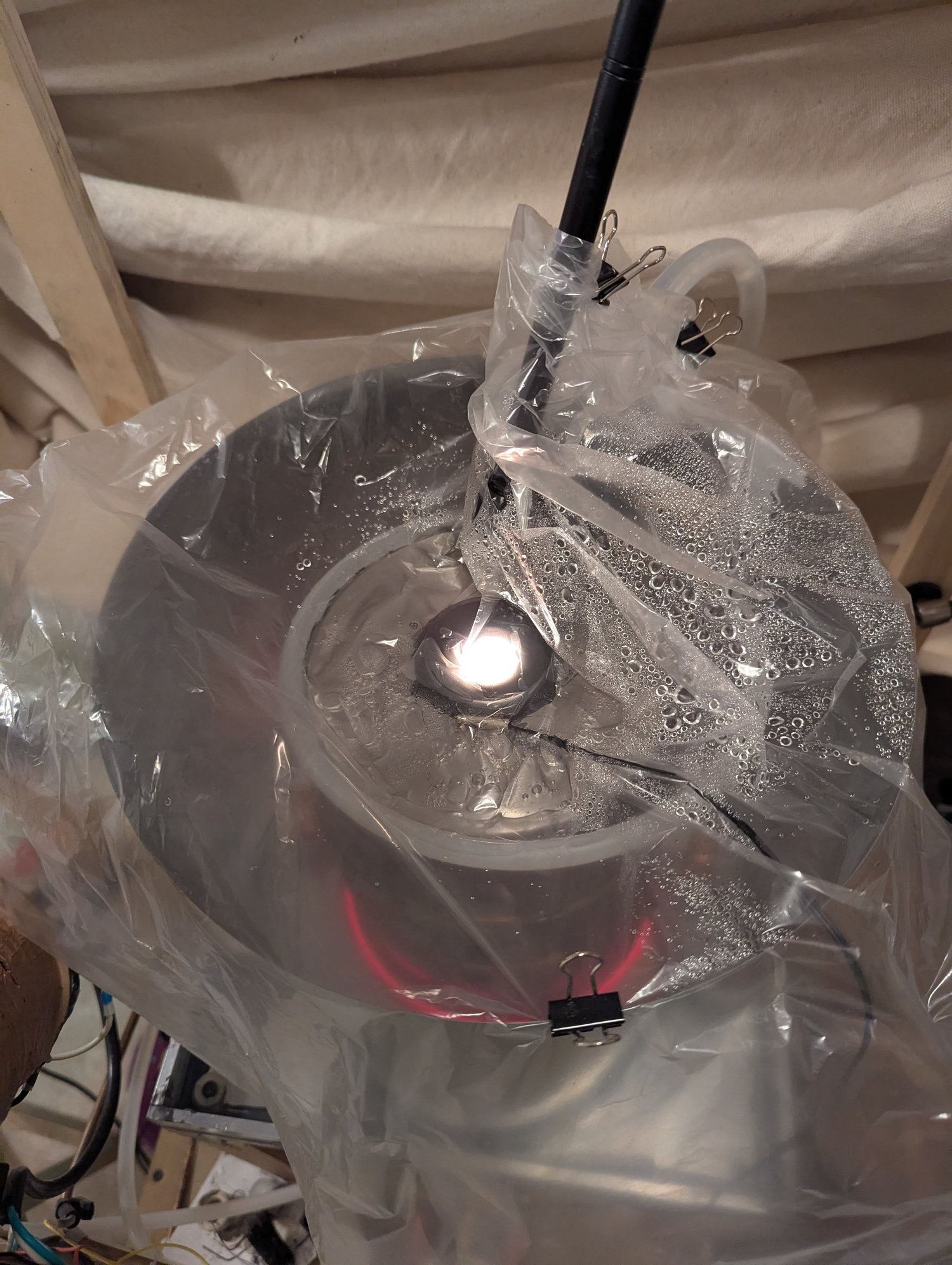
Noodle-pot vacuum furnaceThe noodle pot furnace runningLight from the operating furnace shines through the small glass viewing port on top. A plastic sheet and galvanized shroud surrounded the chamber to contain the cooling-water spray, droplets, and vapor.
Personal project
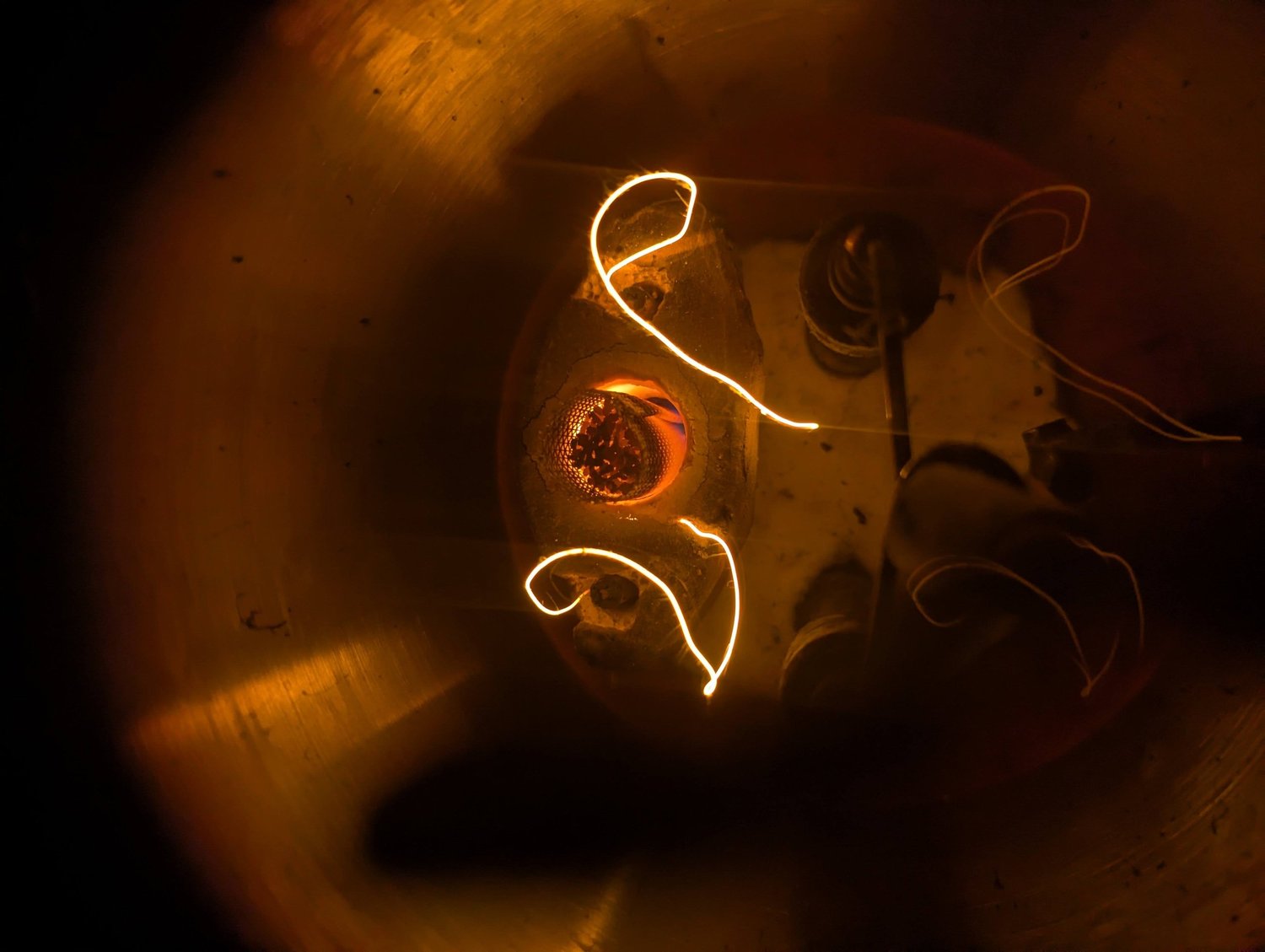
Tungsten oxidation testsHeating titanium sponge from the outsideAn early titanium-sponge getter with nichrome heating wire wrapped around the outside. I later moved a tight heating coil into the center and packed the sponge around it, which seemed more effective. I also suspected that the firebrick and refractory mortar released trapped moisture and gases during heating, making oxygen control harder.
Personal project
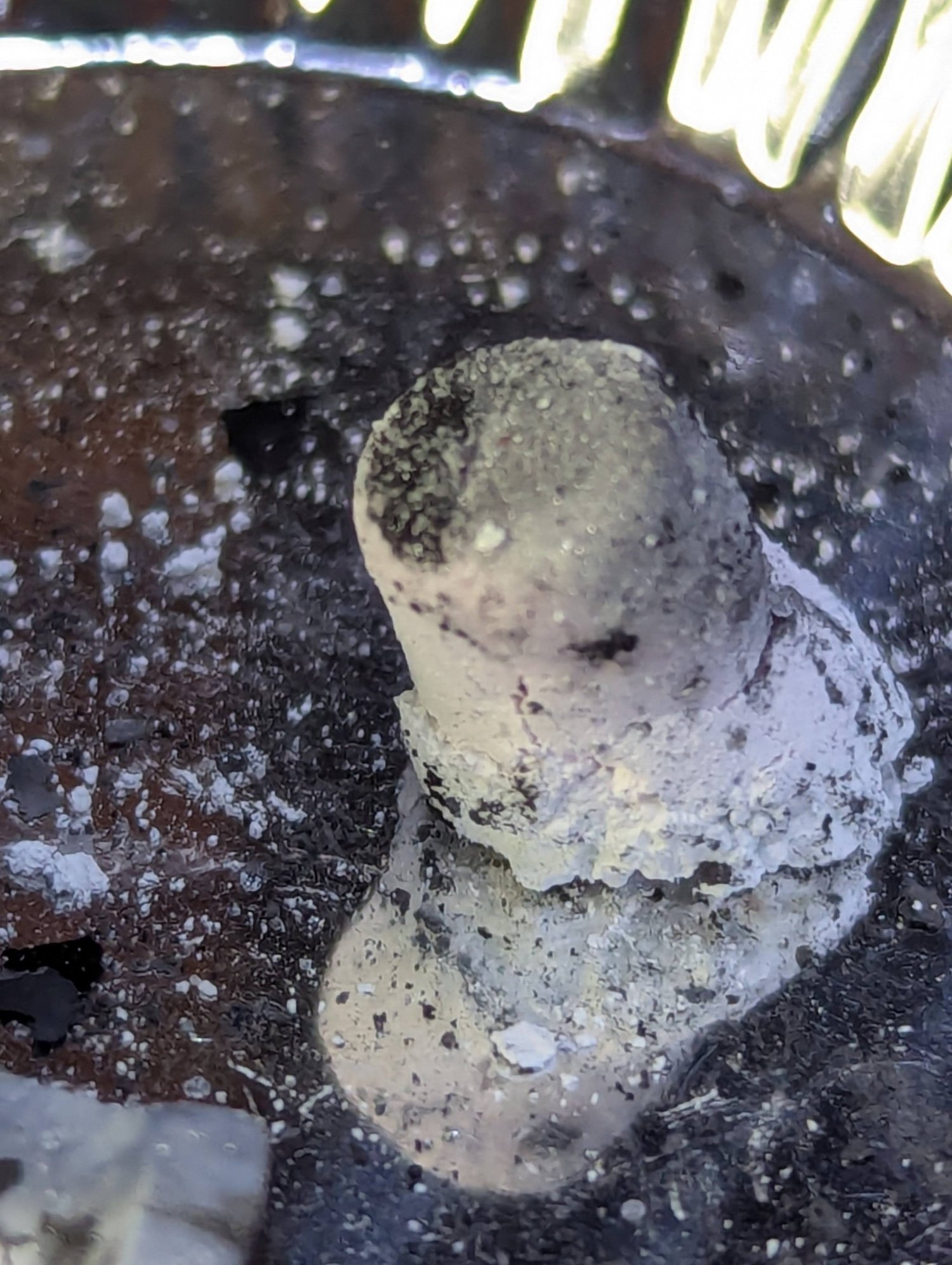
Noodle-pot vacuum furnaceA small alumina heating trialAlumina mixed with chromium oxide in a magnesium-oxide crucible, heated on the tungsten filament as an exploratory ruby-growth test. The sample shrank away from the crucible walls. I later learned that alumina can react with magnesium oxide to form spinel, raising concerns about the crucible reacting with the sample.
Personal project
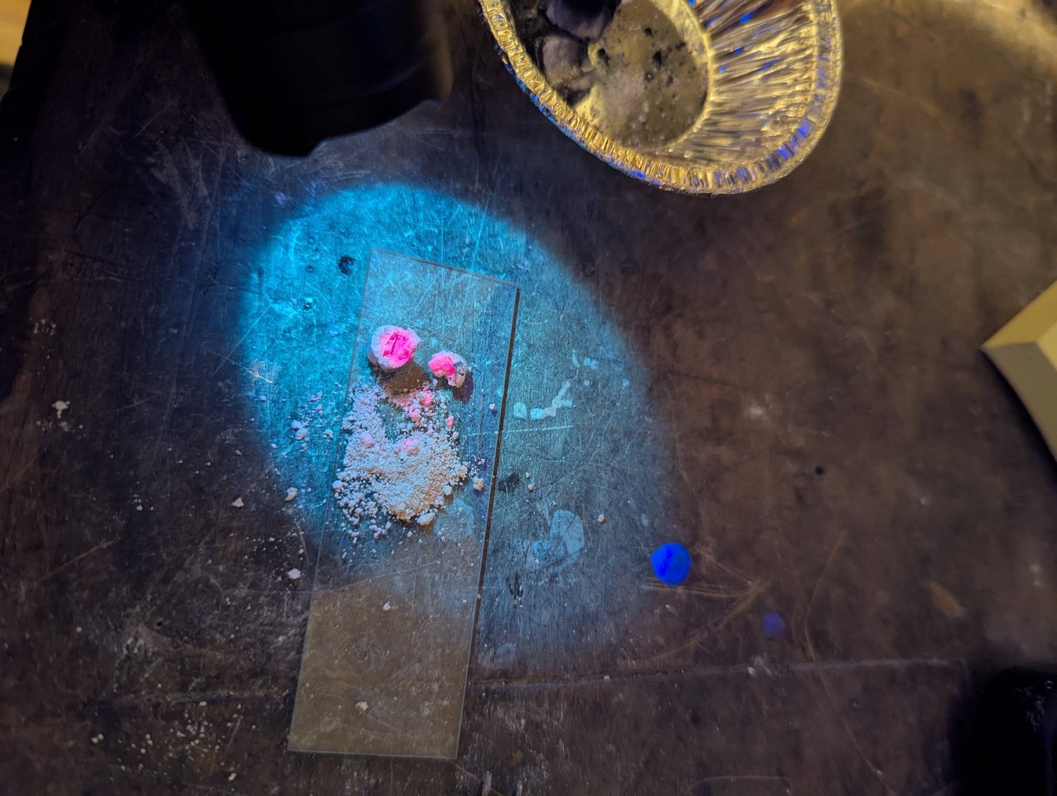
Noodle-pot vacuum furnaceThe test sample under ultraviolet lightThe small alumina and chromium-oxide test sample glowing red under ultraviolet light after heating. This fluorescence was an encouraging observation in my early ruby-growth experiments. The photograph documents the glow, without establishing the sample’s crystal structure or the peak temperature reached.
Personal project
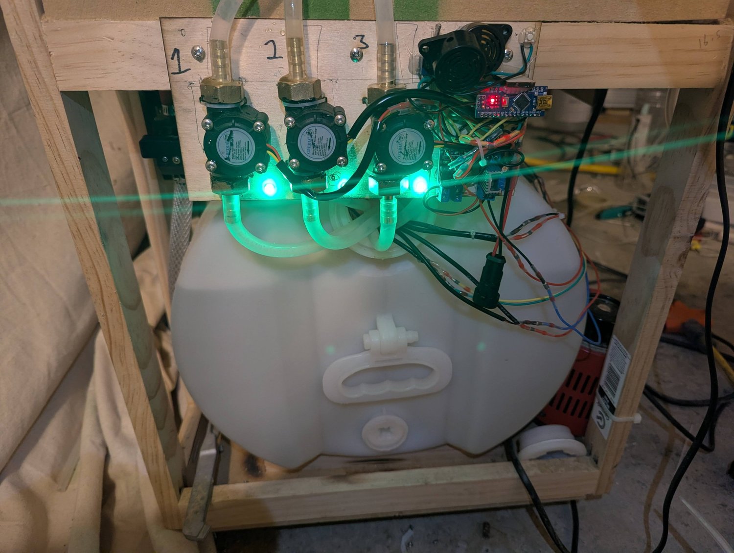
Water-flow alarmMonitoring the cooling-water flowAn Arduino Nano reads flow meters for the furnace’s cooling-water circuits and provides an alarm output, along with output pins for an external relay. I built it to help check that water was circulating through the power transformers, chamber, and electrode holders, all of which needed cooling.
Personal project
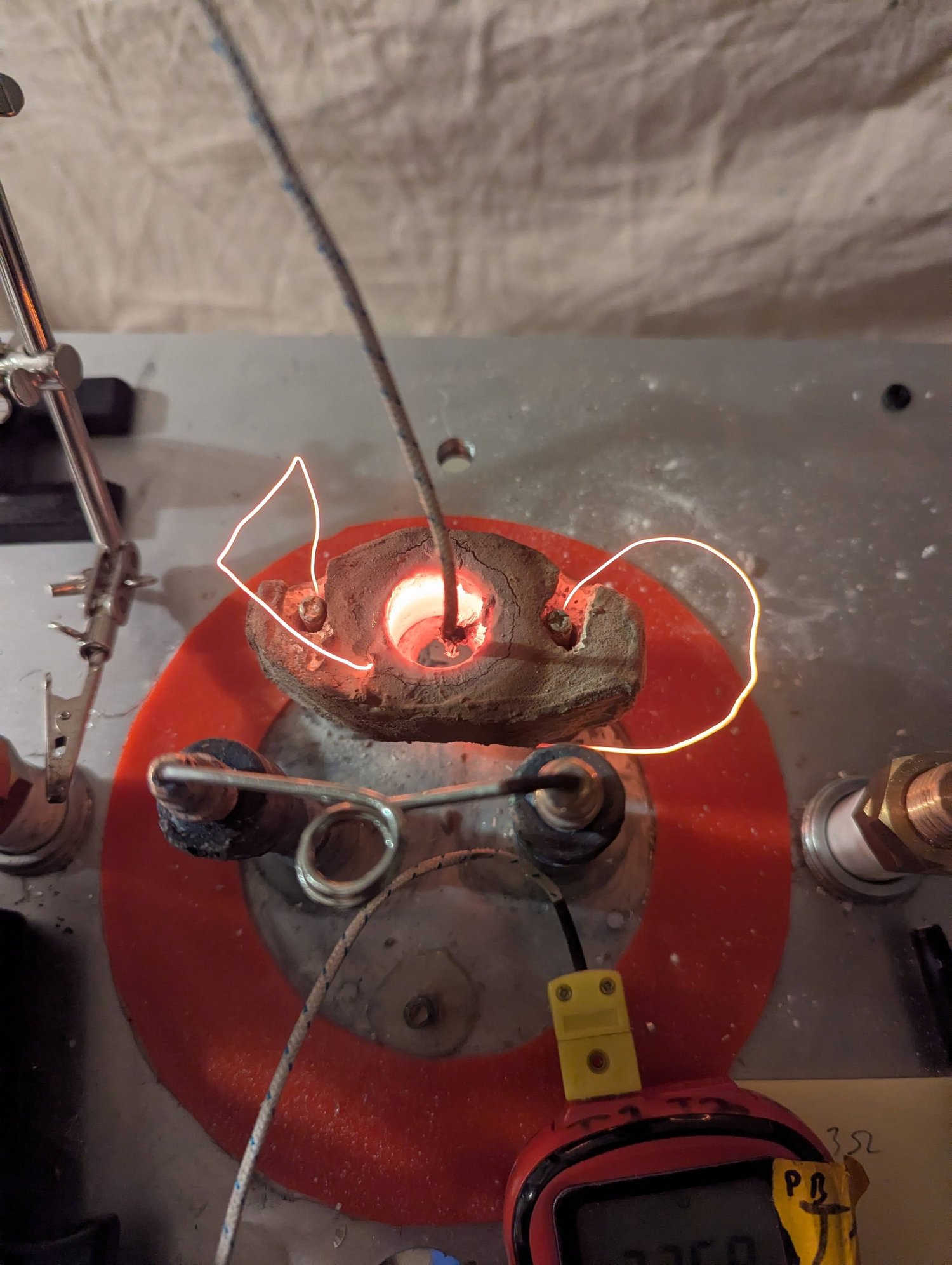
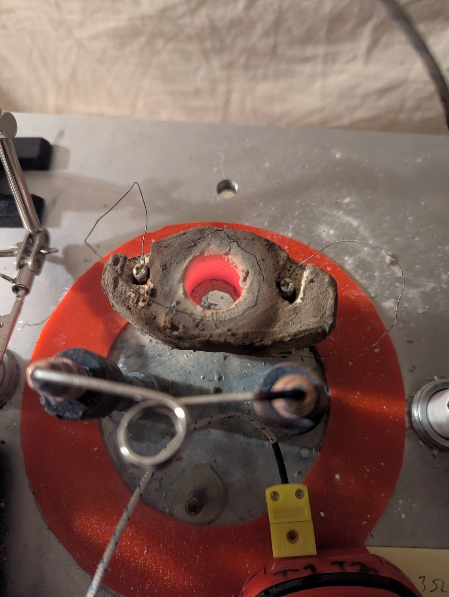
Tungsten oxidation testsAn early getter heaterNichrome wire lines a cavity carved into firebrick to heat the getter material. I recall this version reaching roughly 800°C, although it required running the heating wire very hot. I later replaced it with titanium sponge held around a small central heating coil.
Personal project
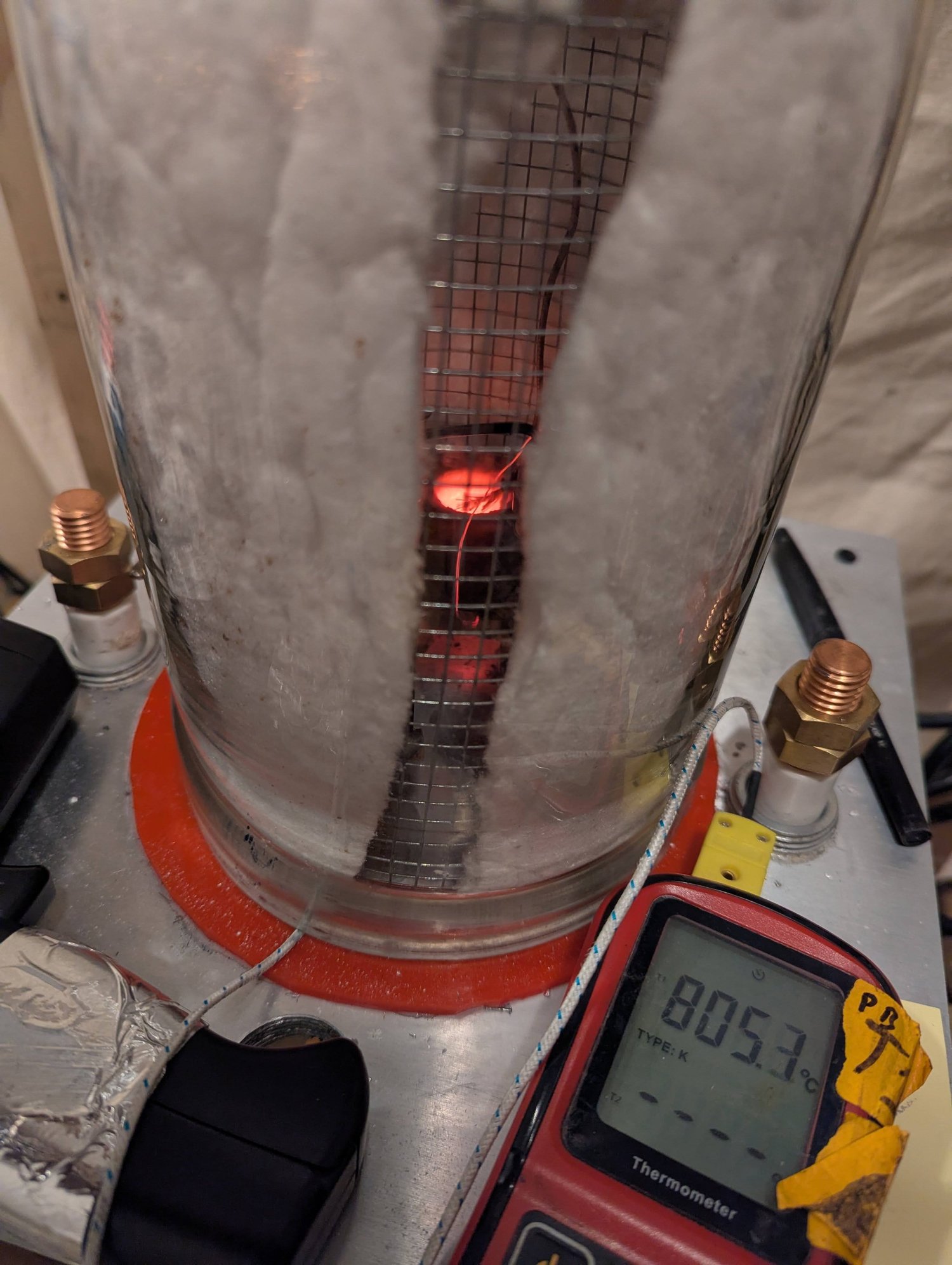
Tungsten oxidation testsAnother view of the firebrick heaterAnother angle on the early getter heater, showing the carved cavity and the nichrome wire around its perimeter. This arrangement heated inward from the outside; the later sponge getter placed the heating coil in the center.
Personal project
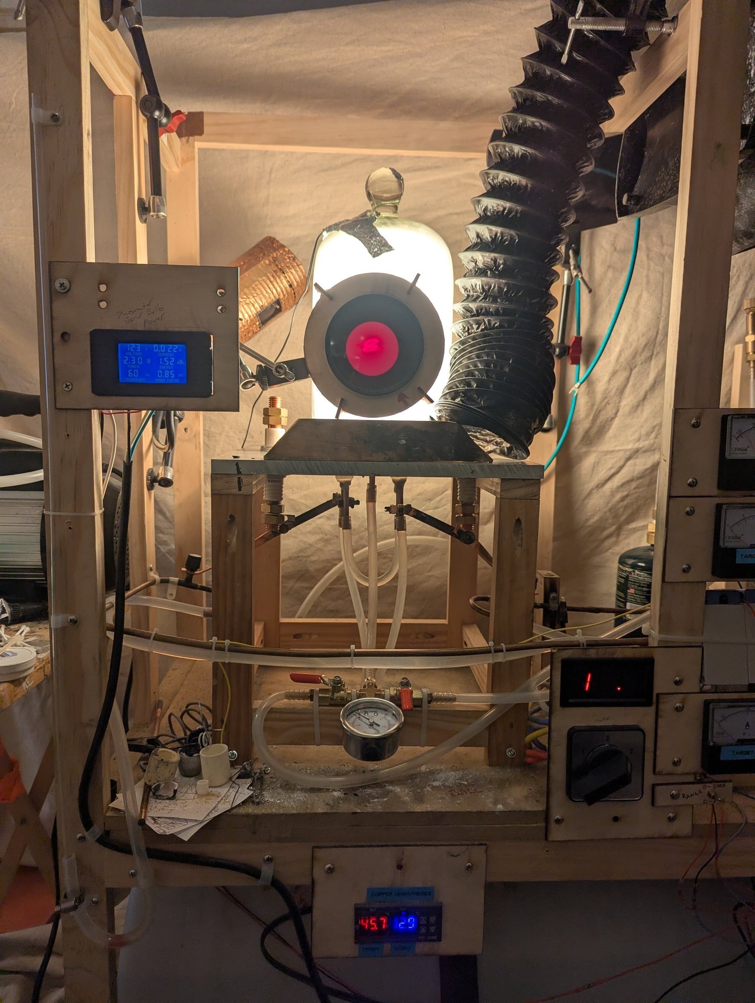
Tungsten oxidation testsTesting the early getter in the chamberThe firebrick-based getter heater installed in a vacuum chamber. I retired this version because I suspected that moisture and gases released by the heated firebrick and mortar were working against the getter. These tests highlighted how sensitive the hot tungsten was to residual oxygen.
Personal project
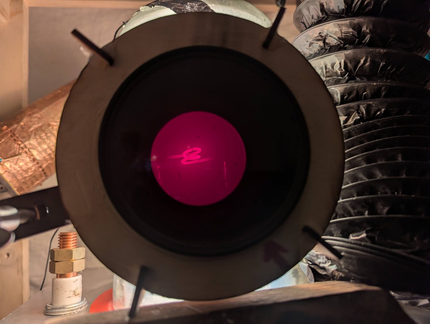
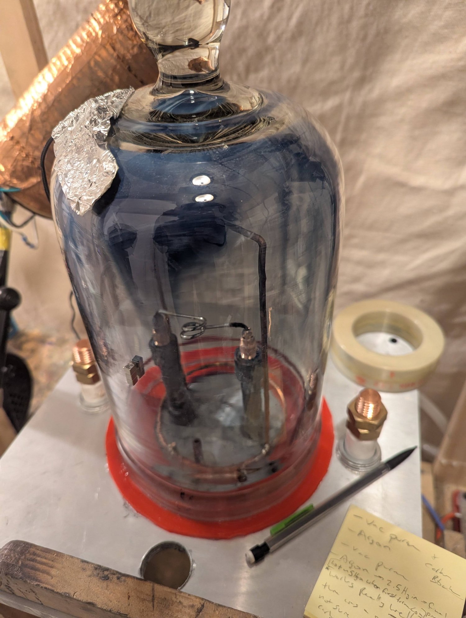
Tungsten oxidation testsWatching tungsten oxidation through a bell jarA glass bell jar let me watch the tungsten filament while it heated and investigate why it deteriorated so quickly. I attributed the cloudy deposits inside the glass to tungsten oxide. The red viewing assembly was borrowed from my optical pyrometer and used filters to reduce the intense light and select a red view of the filament.
Personal project
Tungsten oxidation testsLooking for uneven filament heatingA closer view of the tungsten filament during the bell-jar experiment. I was looking for brighter and darker sections that might reveal uneven heating. This was a visual comparison of the filament’s behavior, not a calibrated temperature map.
Personal project
Tungsten oxidation testsOxide color as a clueA blue coating developed inside the bell jar during a tungsten-filament test. Tungsten trioxide can be yellow, while oxygen-deficient tungsten oxides can appear blue. I interpreted this blue deposit as an oxygen-deficient oxide and used the differences between blue and yellow deposits as qualitative clues while improving oxygen control in the furnace.
Personal project
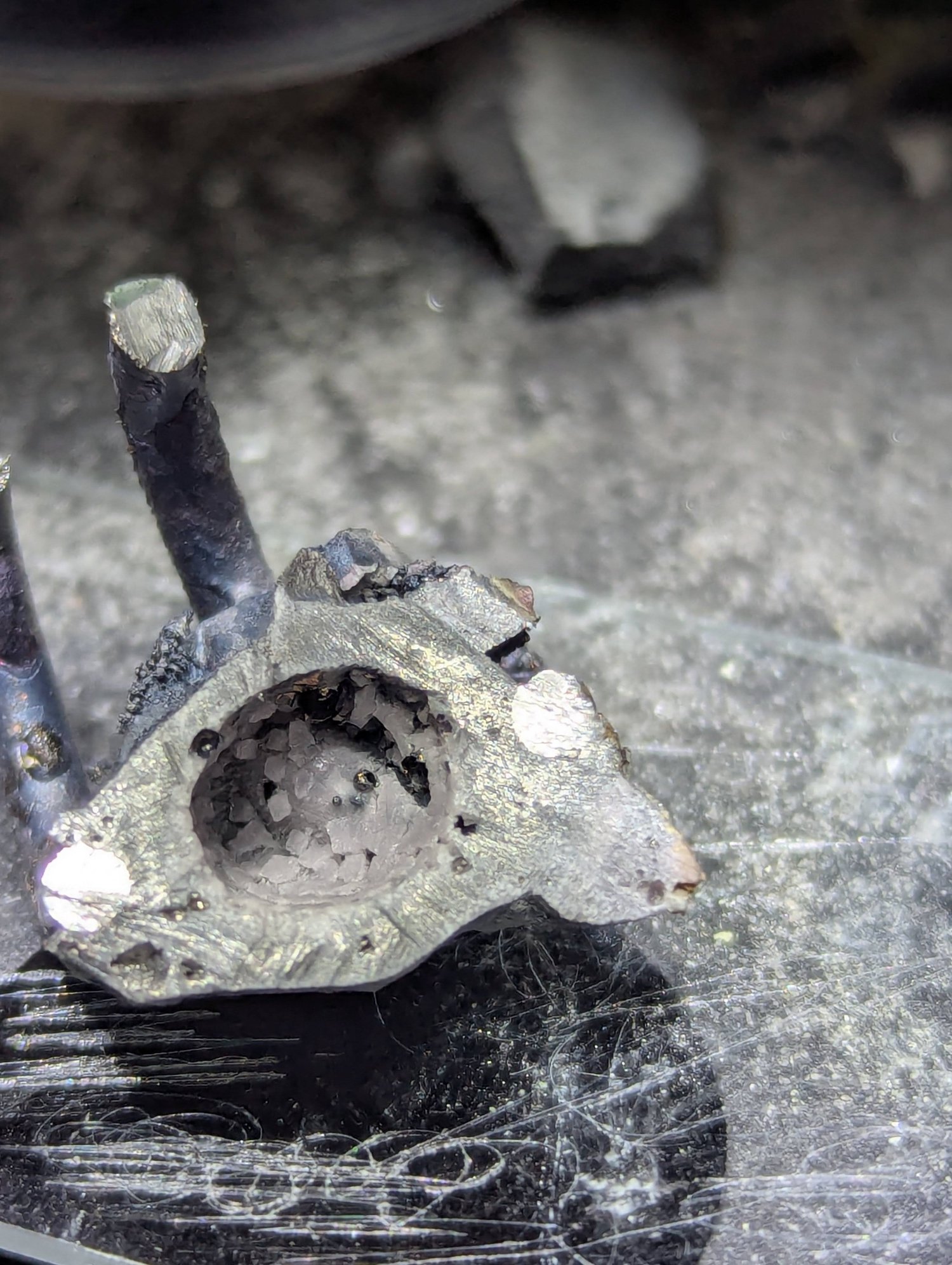
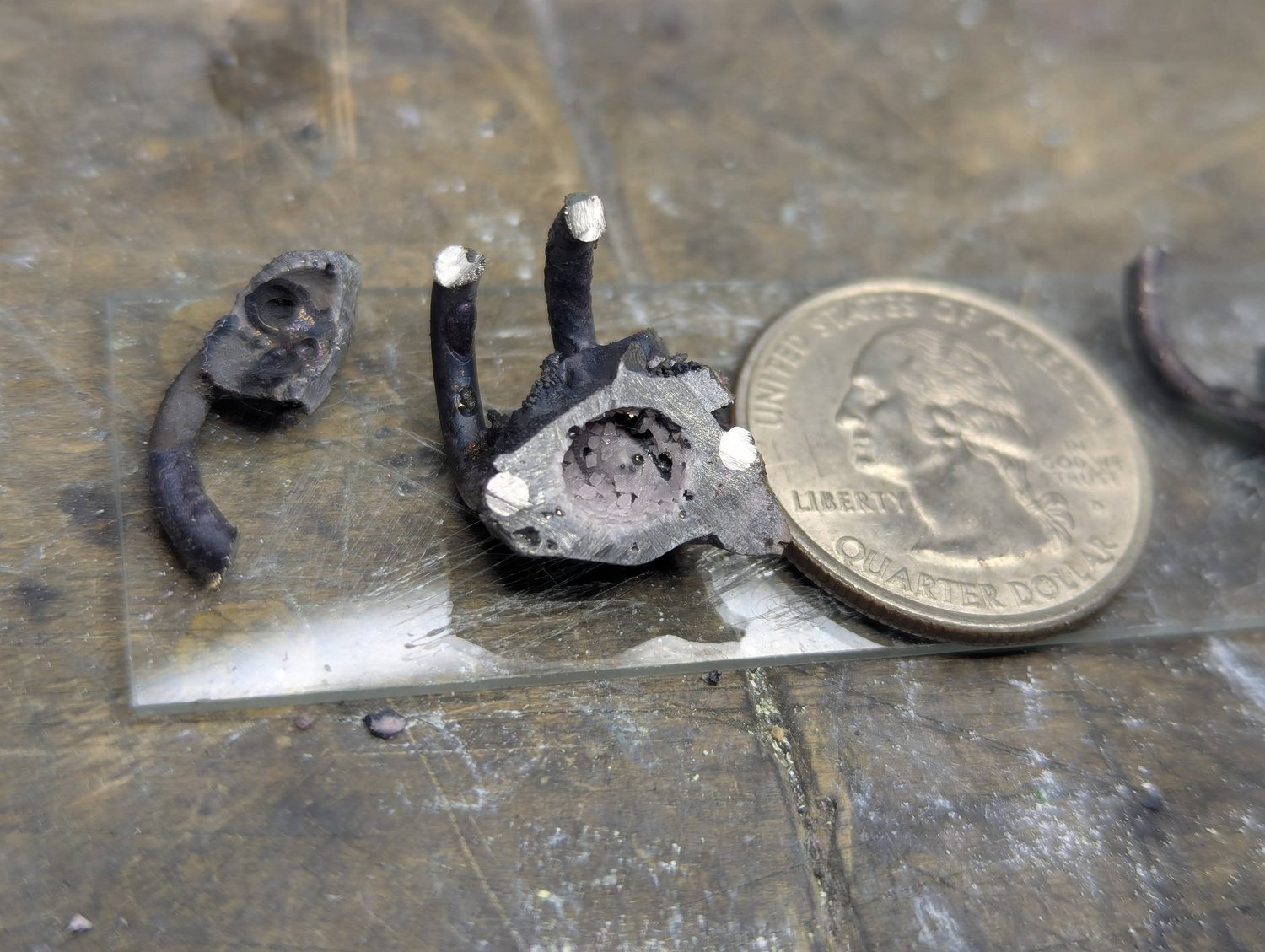
Copper-sphere tungsten furnaceAn unexpected pocket of tiny crystalsI heated alumina rods inside a tungsten coil, hoping the alumina would drip onto a tungsten plate below. Instead, it formed a mass around the coil. When I cut that mass in half, I found a hollow pocket lined with tiny crystals that I identified as sapphire—a happy accident in an experiment intended to make small alumina droplets.
Personal project
Copper-sphere tungsten furnaceCrystal size beside a quarterThe cut alumina mass beside a U.S. quarter for scale. The crystals lining the internal pocket were roughly the size of small salt grains. Finding them was an unexpected result of heating alumina inside the tungsten coil.
Personal project
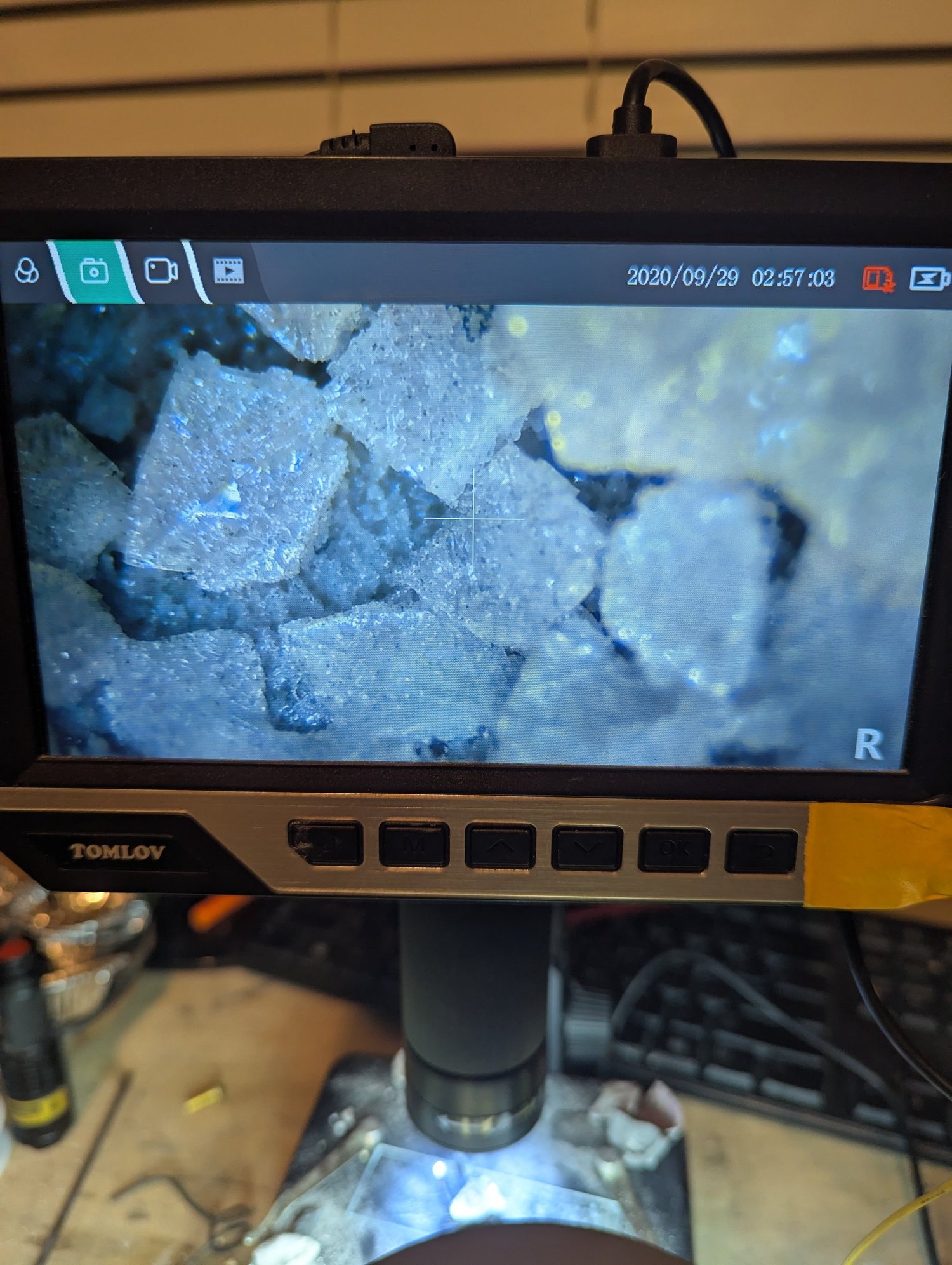
Copper-sphere tungsten furnaceA magnified look inside the pocketA magnified view of the small crystals inside the alumina mass. Cutting the sample open revealed this hidden pocket and made it possible to examine the crystals more closely.
Personal project
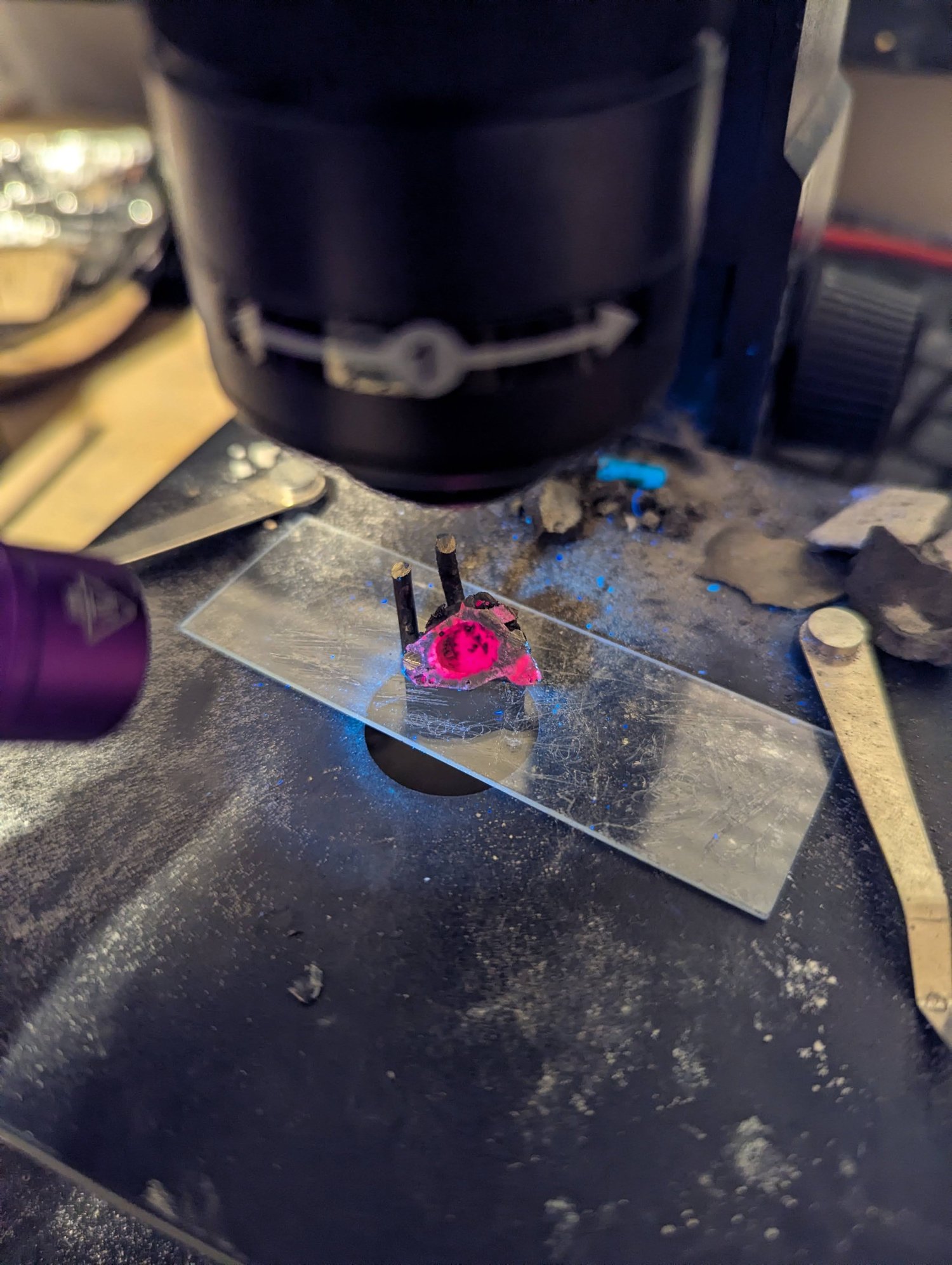
Copper-sphere tungsten furnaceFluorescence inside the alumina massUltraviolet light illuminates the opened alumina mass. The small crystals show a strong fluorescent glow, making the crystal-lined pocket stand out from the surrounding material.
Personal project
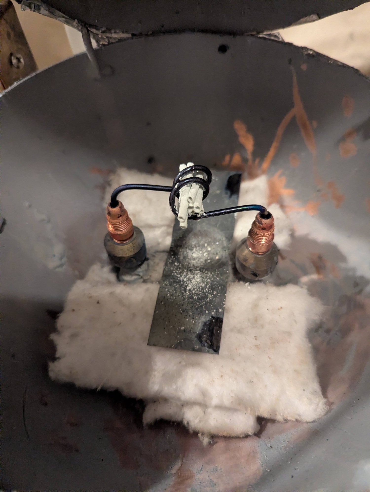
Copper-sphere tungsten furnaceThe early furnace behind the crystal experimentAlumina rods sit inside a tungsten filament made from a TIG welding rod, with a tungsten plate below to catch drips. Copper electrode holders connect through the chamber floor to the power supply. I retired this design because a glass cooling-water connection beneath the insulation could have been exposed to hot material. Later designs focused on keeping cooling water out of the chamber. The yellow-white wall deposits were a recurring oxidation problem.
Personal project
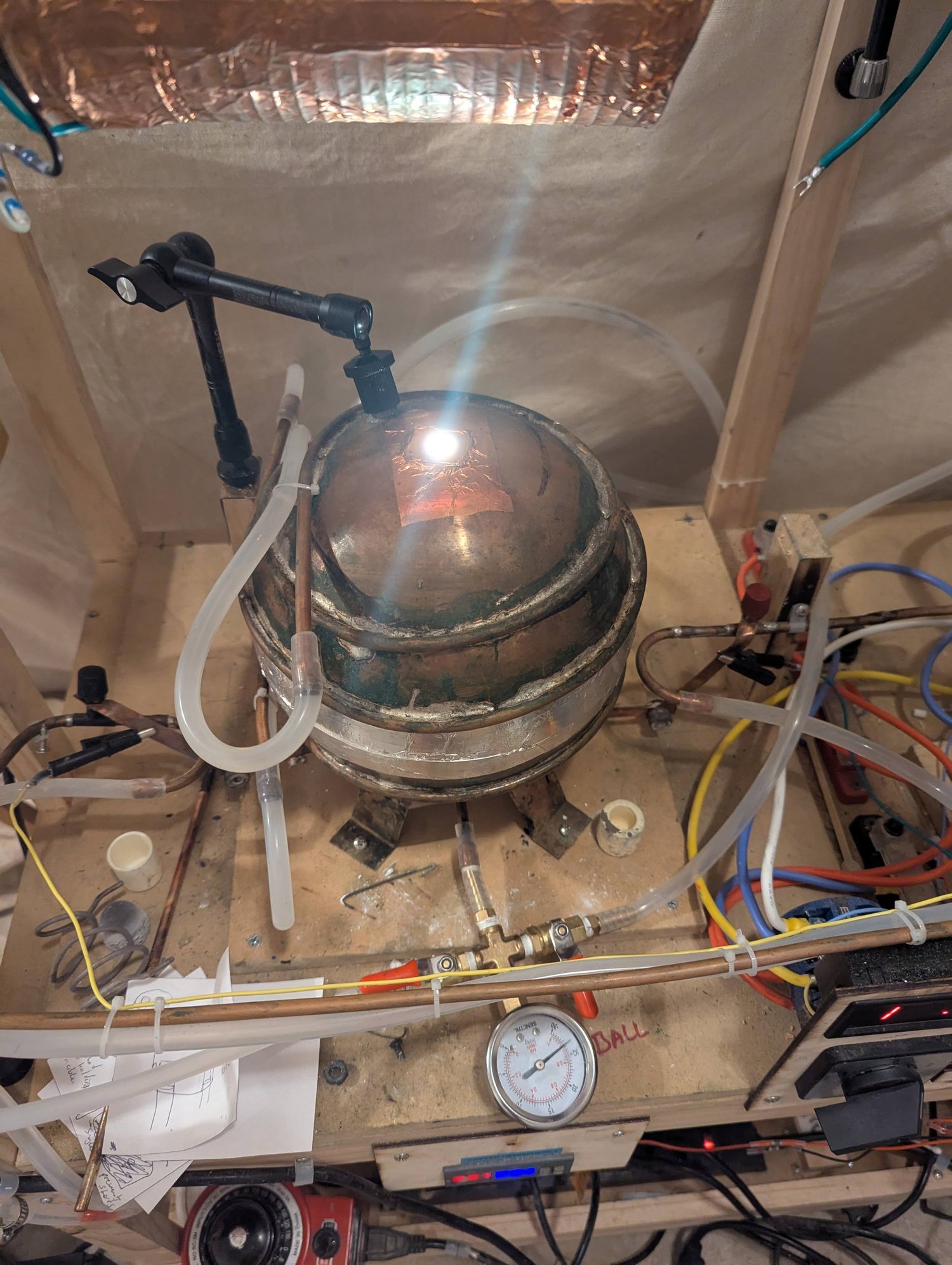
Copper-sphere tungsten furnaceClosing the copper-sphere chamberThe two copper hemispheres assembled into a furnace chamber, with aluminum tape sealing the joint. Recurring tungsten-oxide deposits taught me how important oxygen control was. This early setup also used threaded pipe fittings and silicone tubing, which I later reconsidered as I improved the chamber and vacuum connections.
Personal project
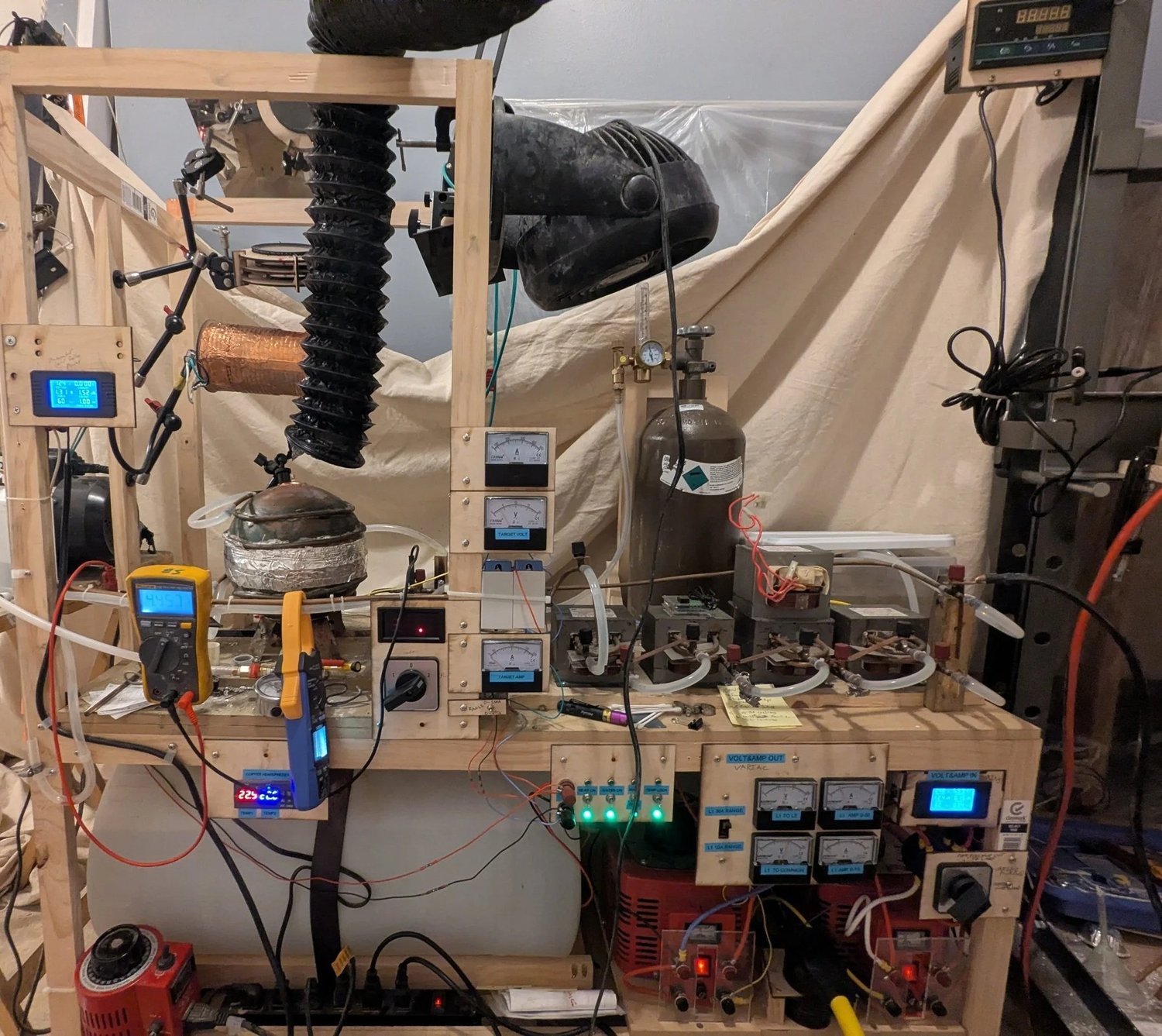
Copper-sphere tungsten furnaceThe furnace and its growing collection of instrumentsThe copper-sphere furnace alongside its power and monitoring equipment. Four rewound microwave-oven transformers supplied high current, and an argon cylinder provided purge gas. Meters tracked filament current and voltage, input and output voltage at the adjustable transformers, and total input power. I added instruments over time as new questions came up during testing.
Personal project
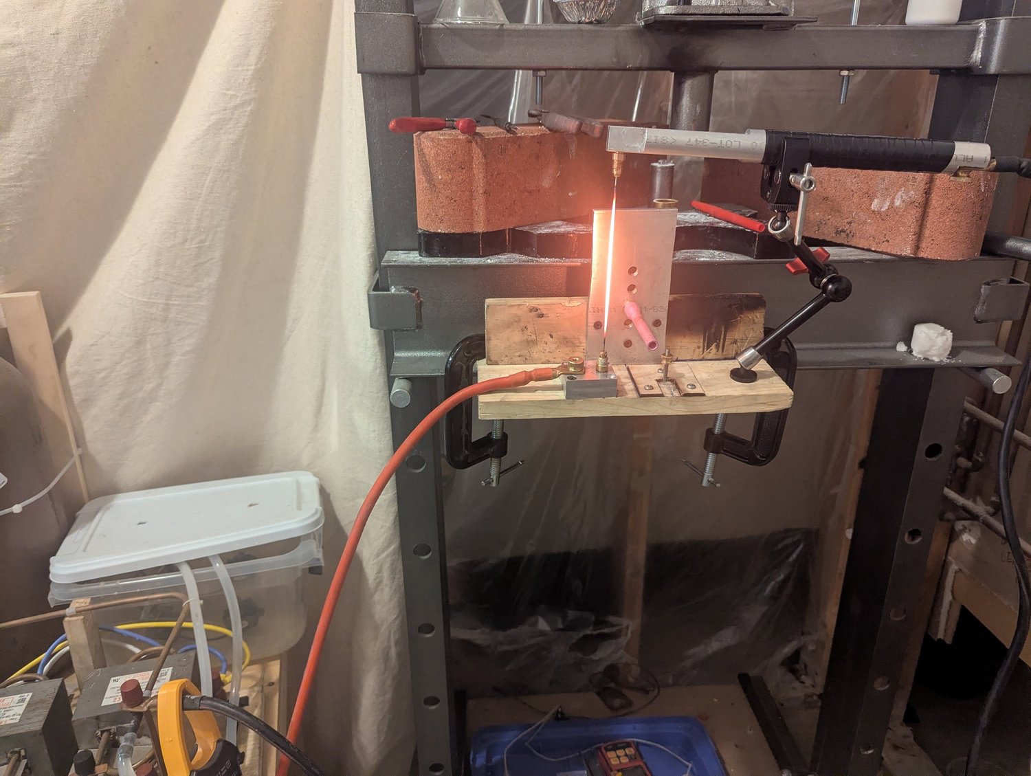
Tungsten filament toolingMy earlier tungsten-filament winding methodThis is the winding fixture I used before my current setup shown in Photos 500 and 501. One end of the tungsten rod stayed fixed while the other was wound around a long alumina mandrel, the form that guided the coil’s shape. It made usable filaments, although getting the same shape each time was difficult.
Personal project
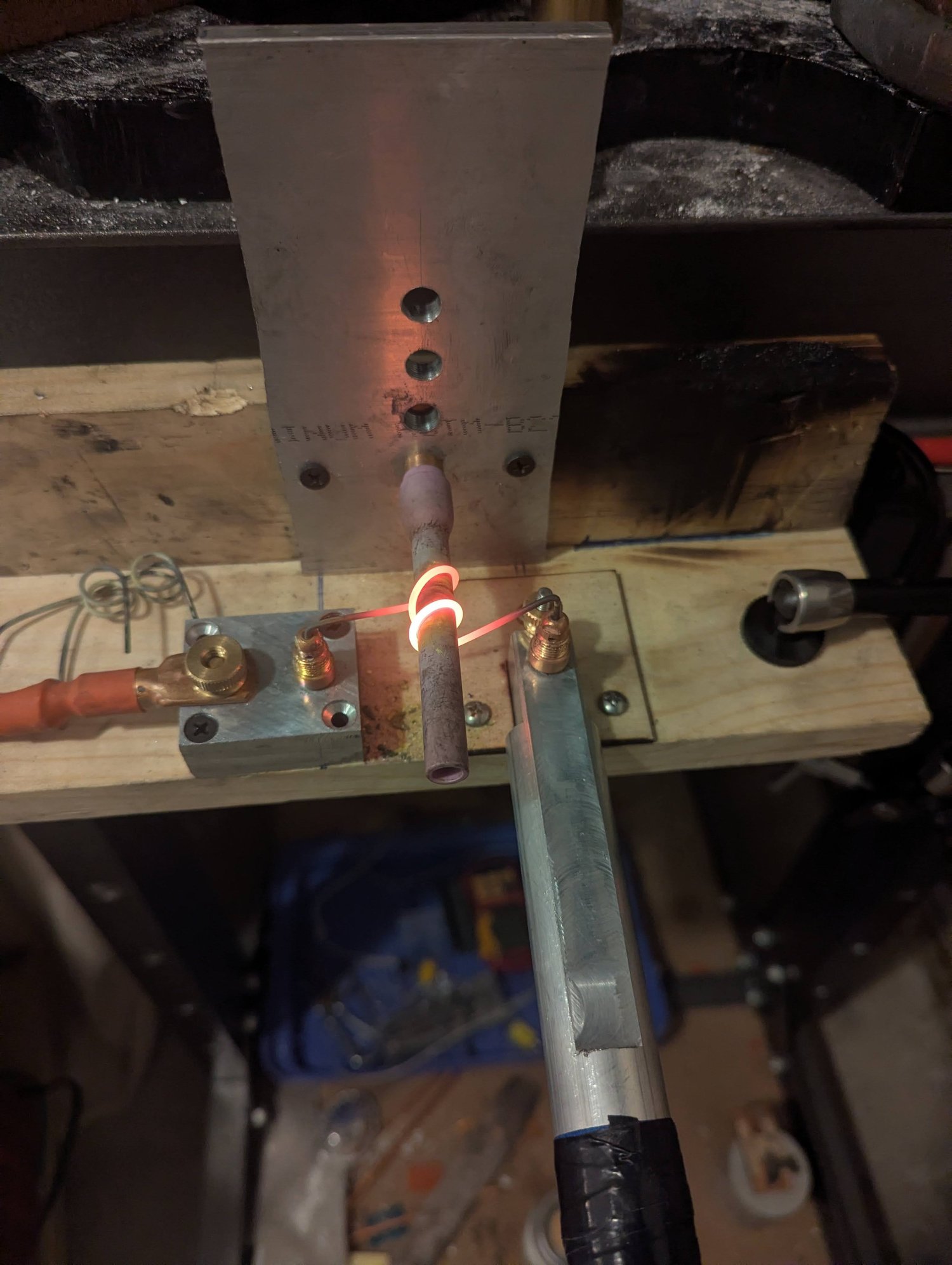
Tungsten filament toolingThe earlier winding method in useThe earlier tungsten winding operation in progress. The alumina mandrel supported the rod as it was formed into a coil. I used this method for the early furnace experiments; my current winding fixture is shown at the top of this project in Photos 500 and 501.
Personal project
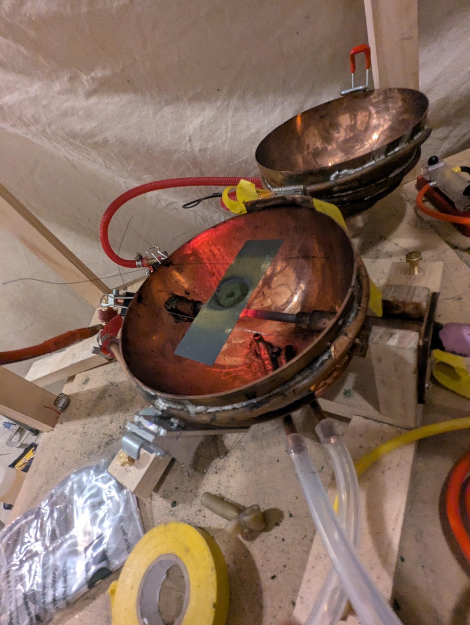
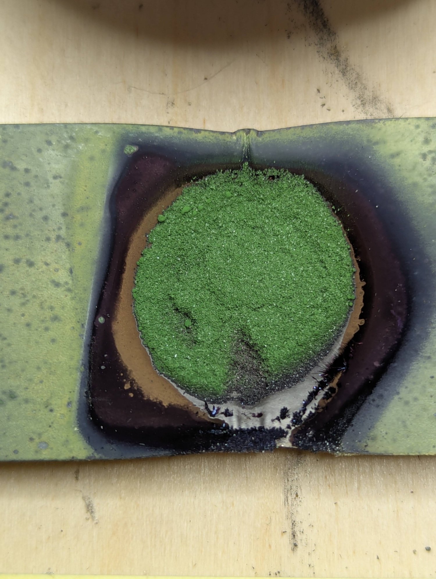
Carbon-arc furnaceTrying a carbon arc as the heat sourceBefore using tungsten filaments, I tried heating alumina on a tungsten plate with an arc between two carbon electrodes. I positioned the arc close to the plate, but the approach introduced heavy carbon contamination and did not achieve the heating result I wanted.
Personal project
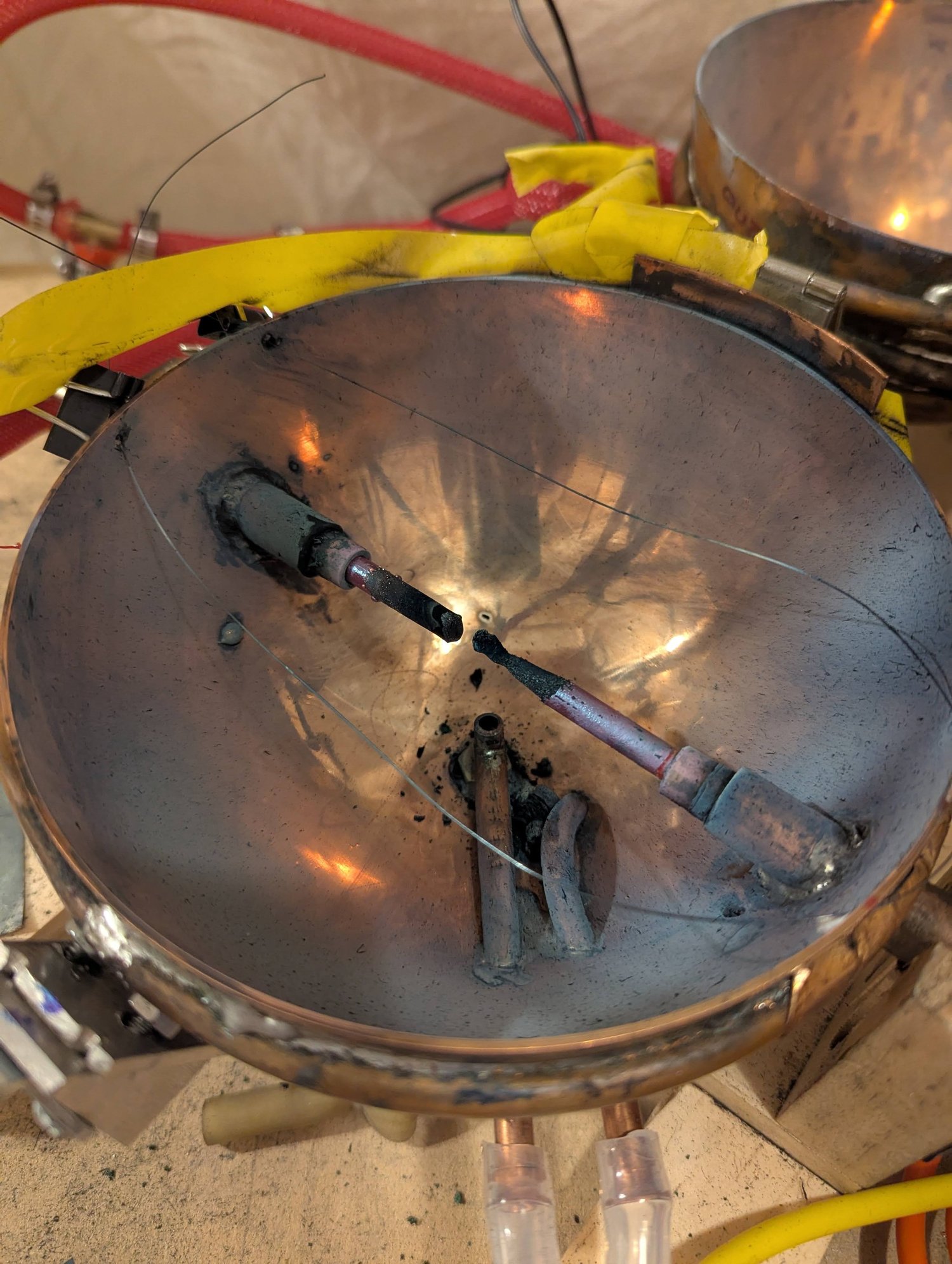
Carbon-arc furnace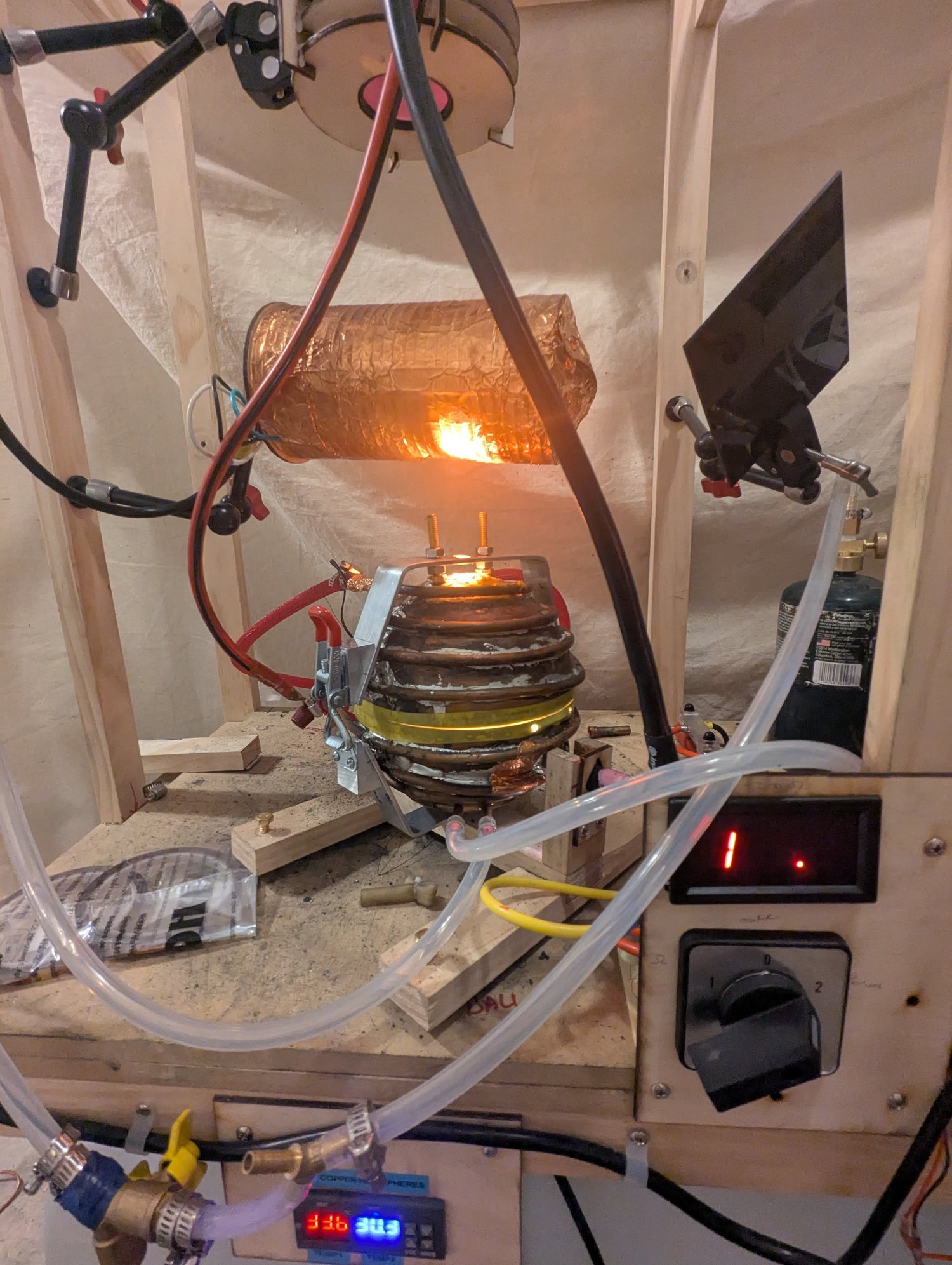
Personal project
Carbon-arc furnaceThe carbon-arc furnace operatingThe bright carbon arc during a heating test. The electrodes were consumed as it ran, so they needed to be advanced to maintain the arc. Automating that movement would have added another control system, making this approach less attractive for the furnace.
Personal project
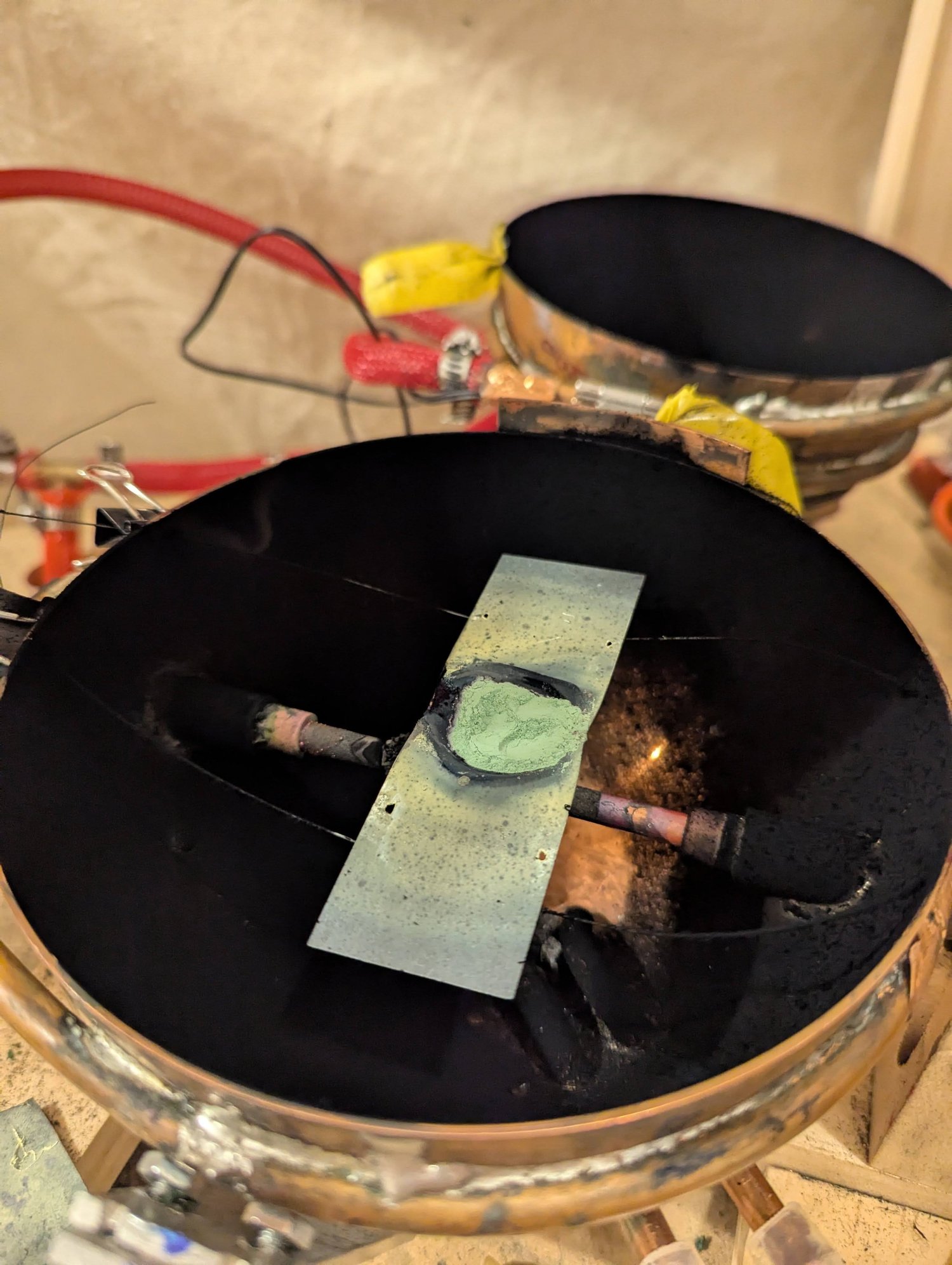
Carbon-arc furnaceCarbon contamination after a testSoot coats the inside of the copper hemispheres after carbon-arc heating. The contamination was one of the main reasons I abandoned this heat source: carbon was being introduced into a process where I wanted to control the material’s purity.
Personal project
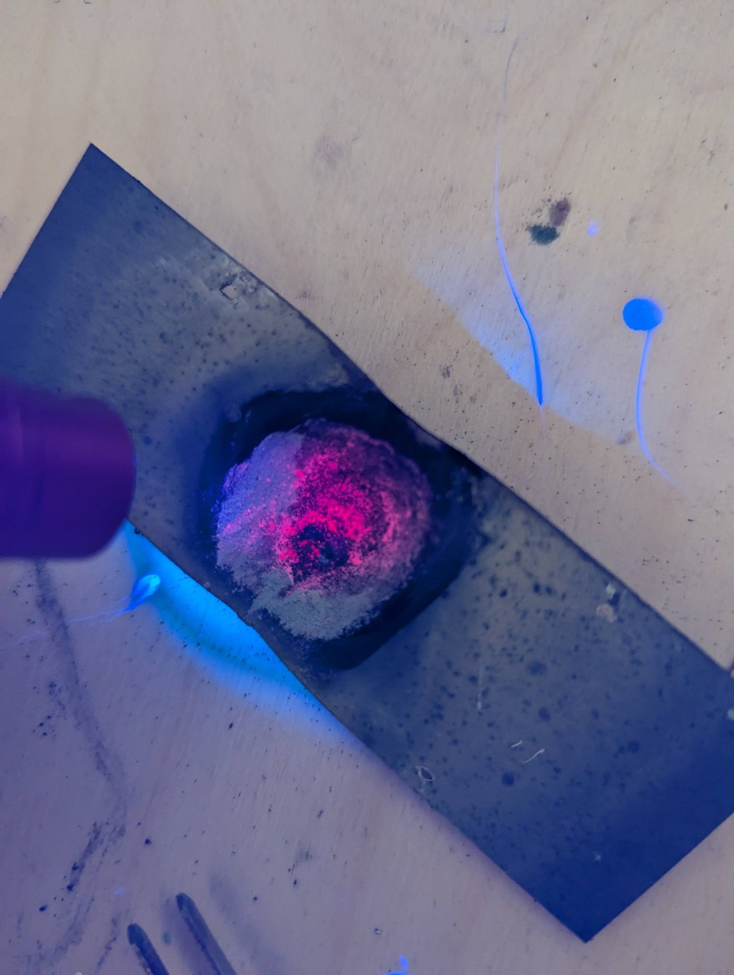
Carbon-arc furnaceExamining the carbon-arc test sampleThe alumina sample under ultraviolet light after a carbon-arc heating test, showing some fluorescence. Even with this visible response, the contamination, electrode-feeding requirements, and limited heating performance made the approach unsuitable for the experiment I wanted to pursue.
Personal project
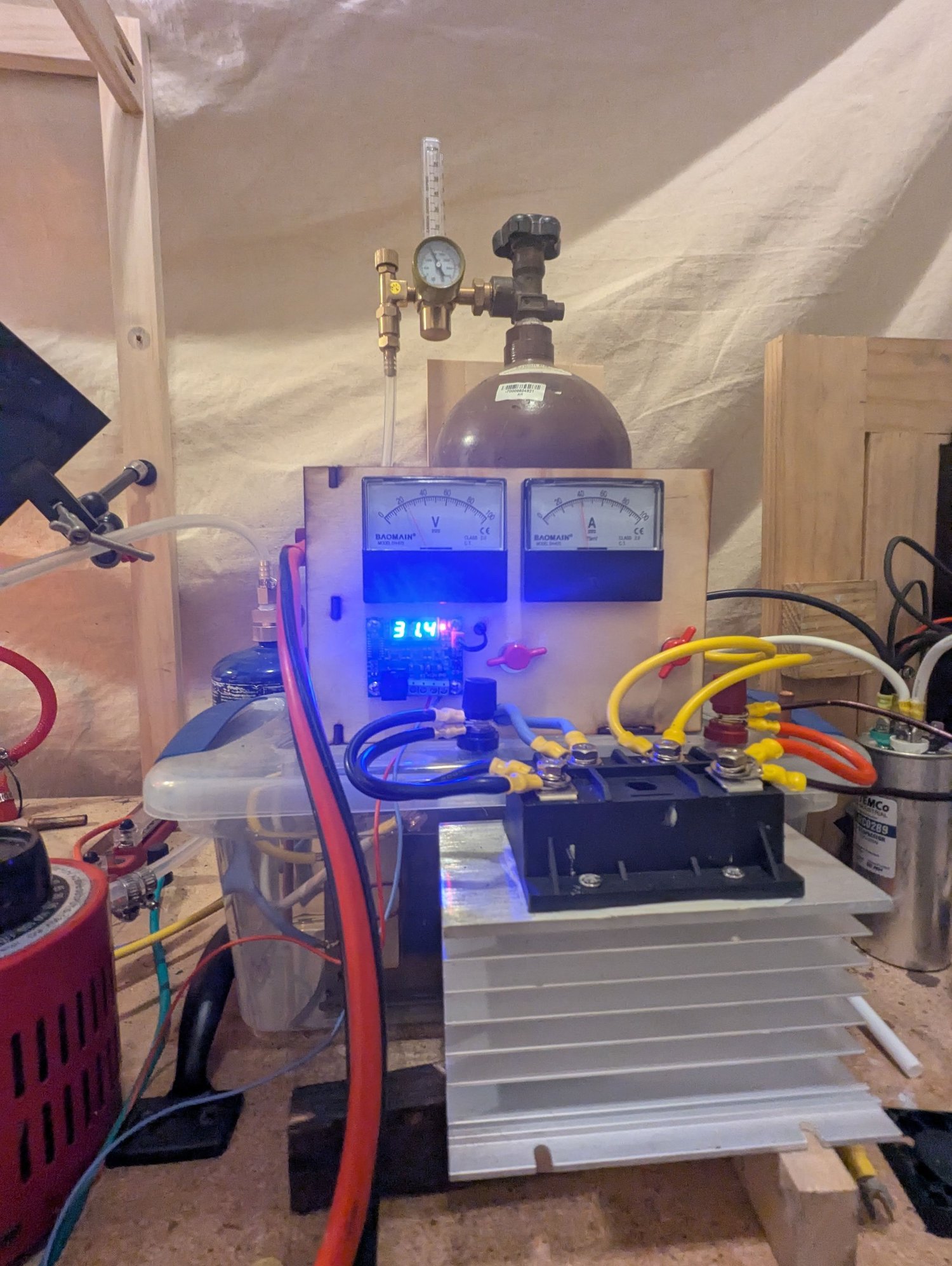
Carbon-arc furnaceA view of the carbon arcThe carbon-arc heat source during a furnace test. An electrical discharge between the carbon electrodes produced the intense light and heat. Keeping the arc running as the electrodes wore away was one of the practical challenges of this design.
Personal project
Carbon-arc furnaceAnother carbon-arc heating trialAnother image from the carbon-arc furnace experiments. These trials helped me compare heat sources and understand the effects of contamination before moving on to tungsten-filament heating.
Personal project
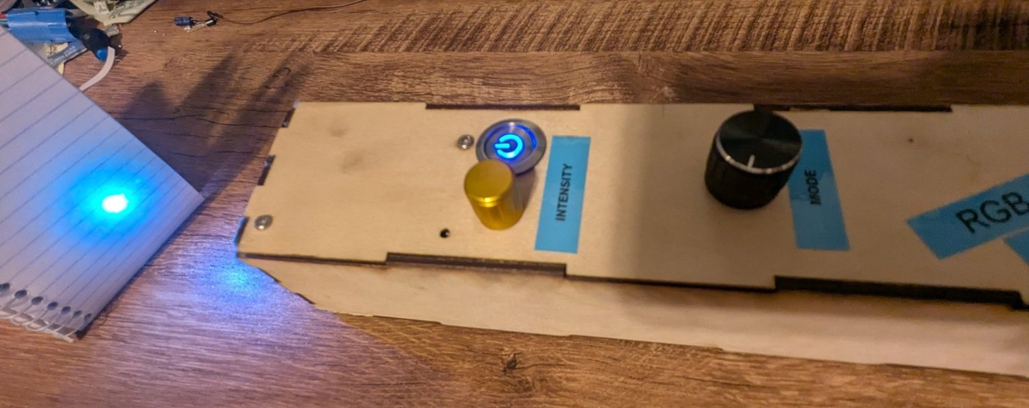
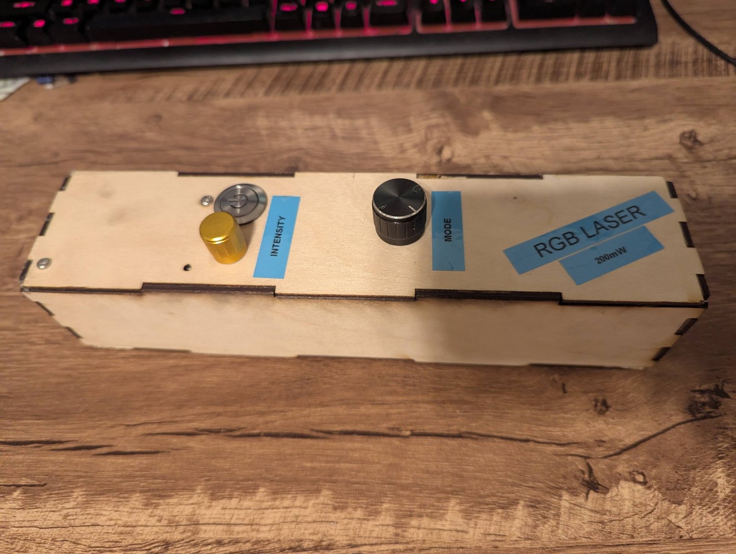
RGB laser pointerA laser pointer with selectable colors and patternsAn RGB laser pointer I built around an inexpensive module combining red, green, and blue lasers with dichroic mirrors—mirrors that selectively transmit or reflect different colors. A pushbutton turns it on, the yellow dial adjusts intensity, and the black selector offers 12 color and pattern settings, including mixed colors, white, flashing, and sparkle effects.
Personal project
RGB laser pointerTesting the combined laser beamAnother view of the RGB laser-pointer project. I discovered that the inexpensive module’s lasers and combining mirrors were poorly aligned: the colors appeared to meet nearby but separated farther away. It was a useful lesson in how much alignment matters when combining several beams.
Personal project
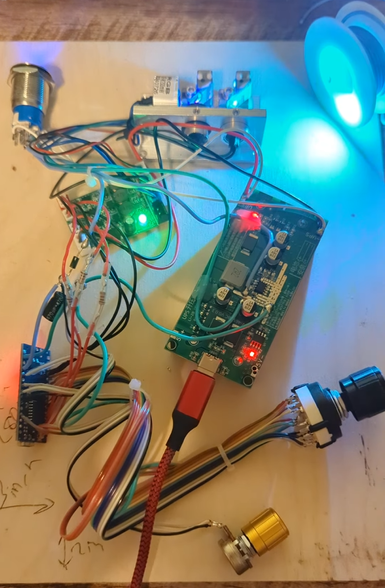
RGB laser pointerInside the RGB laser pointerThe opened assembly shows the laser module, power electronics, and wiring to the controls. I recall adapting the power supply from a small battery-backup unit that used 18650 lithium cells. I modified it to supply power on demand and adapted the laser-driver circuit to accept power and control signals from an Arduino Nano, which coordinated the colors and patterns.
Personal project
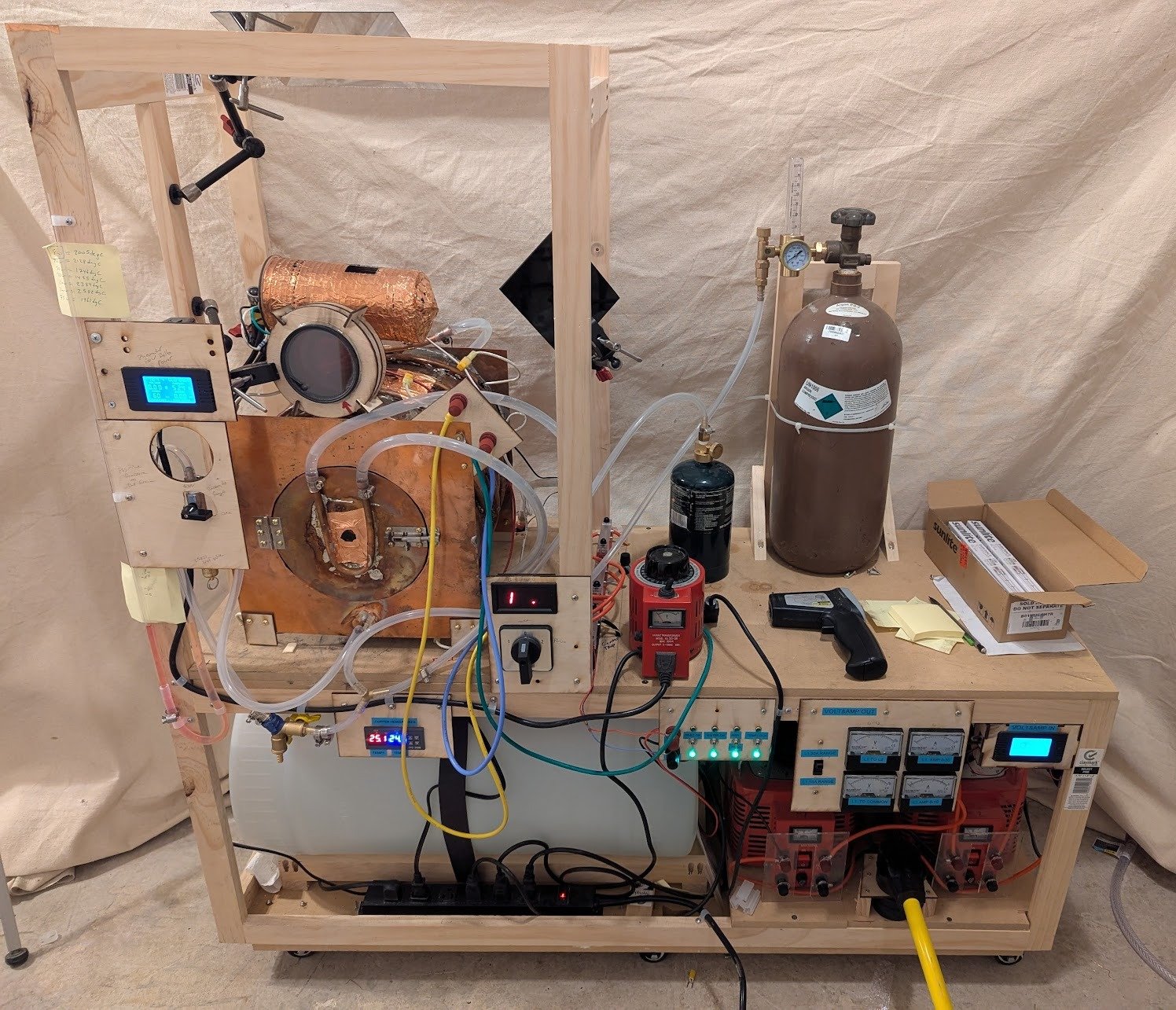
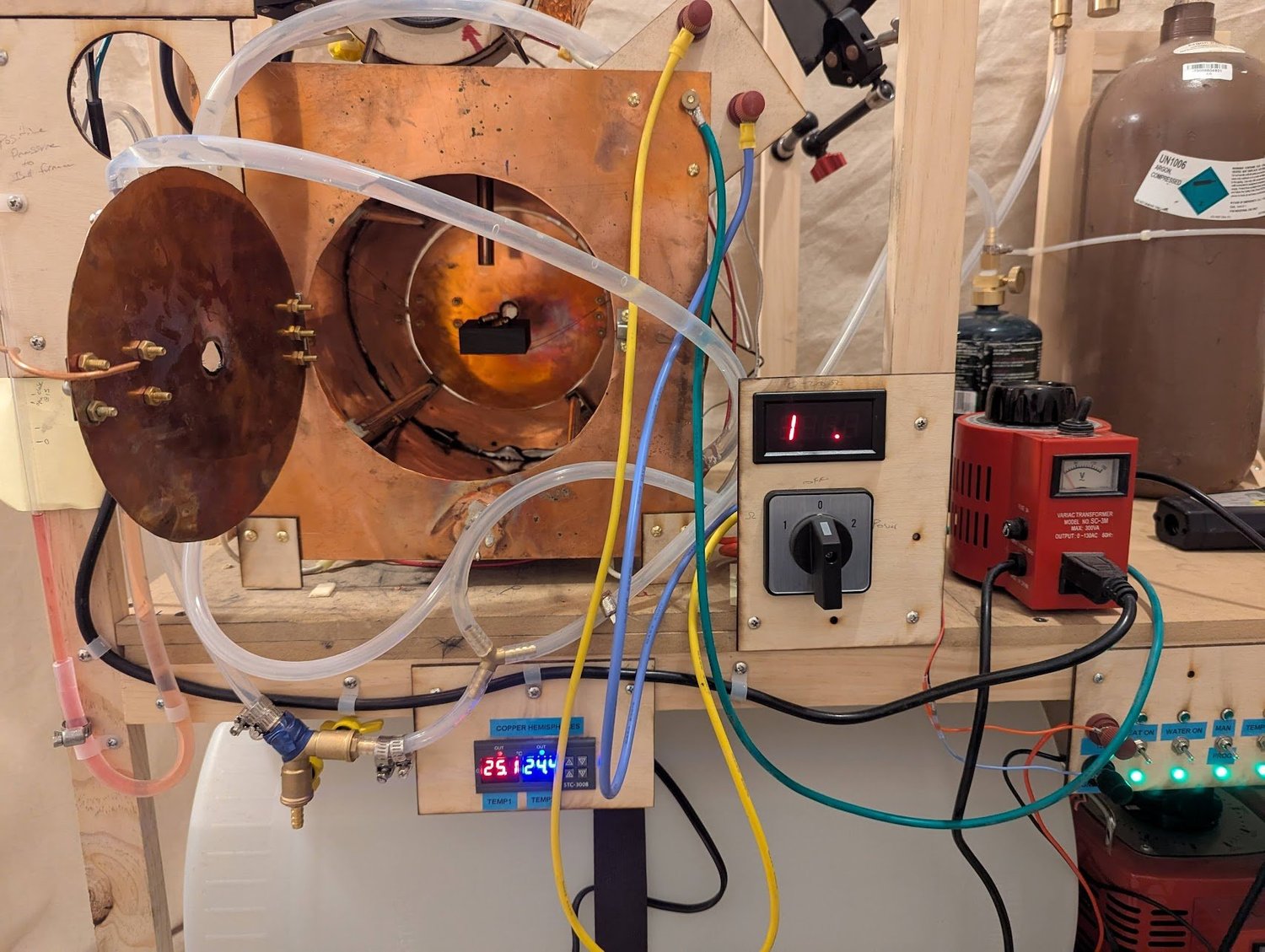
Infrared mirror ovenAn experimental infrared ovenAn infrared oven built around a copper cylinder and, as I recall, four halogen lamps rated at about 1,500 watts each. Two variable transformers, or Variacs, controlled the power, while water cooling helped manage the copper body’s temperature. The idea was to direct the lamps’ radiant heat toward a graphite platform or crucible suspended in the center on tungsten wire.
Personal project
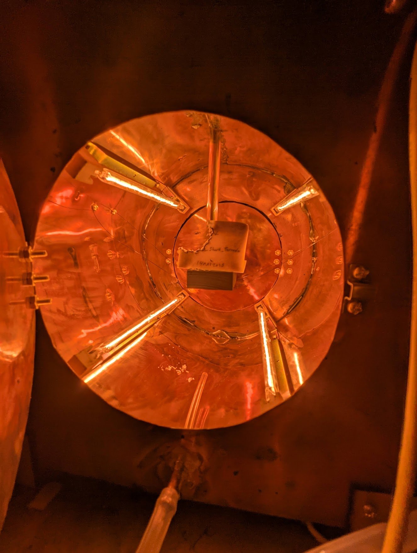
Infrared mirror ovenThe suspended graphite platformA view inside the infrared oven, showing the graphite platform suspended near the center of the copper cylinder. Tungsten wire supported the platform while leaving it exposed to light from the surrounding lamps. I also added thermocouples—small temperature sensors—to monitor heating in the oven and cooling system.
Personal project
Infrared mirror ovenThe infrared oven at low powerThe lamps glowing during a low-power test. I polished the copper interior to reflect more light toward the central graphite platform. The oven looked striking, but its heating performance did not make it useful for the melting experiments I had in mind. Building it was a valuable exercise in forming and working with copper.
Personal project
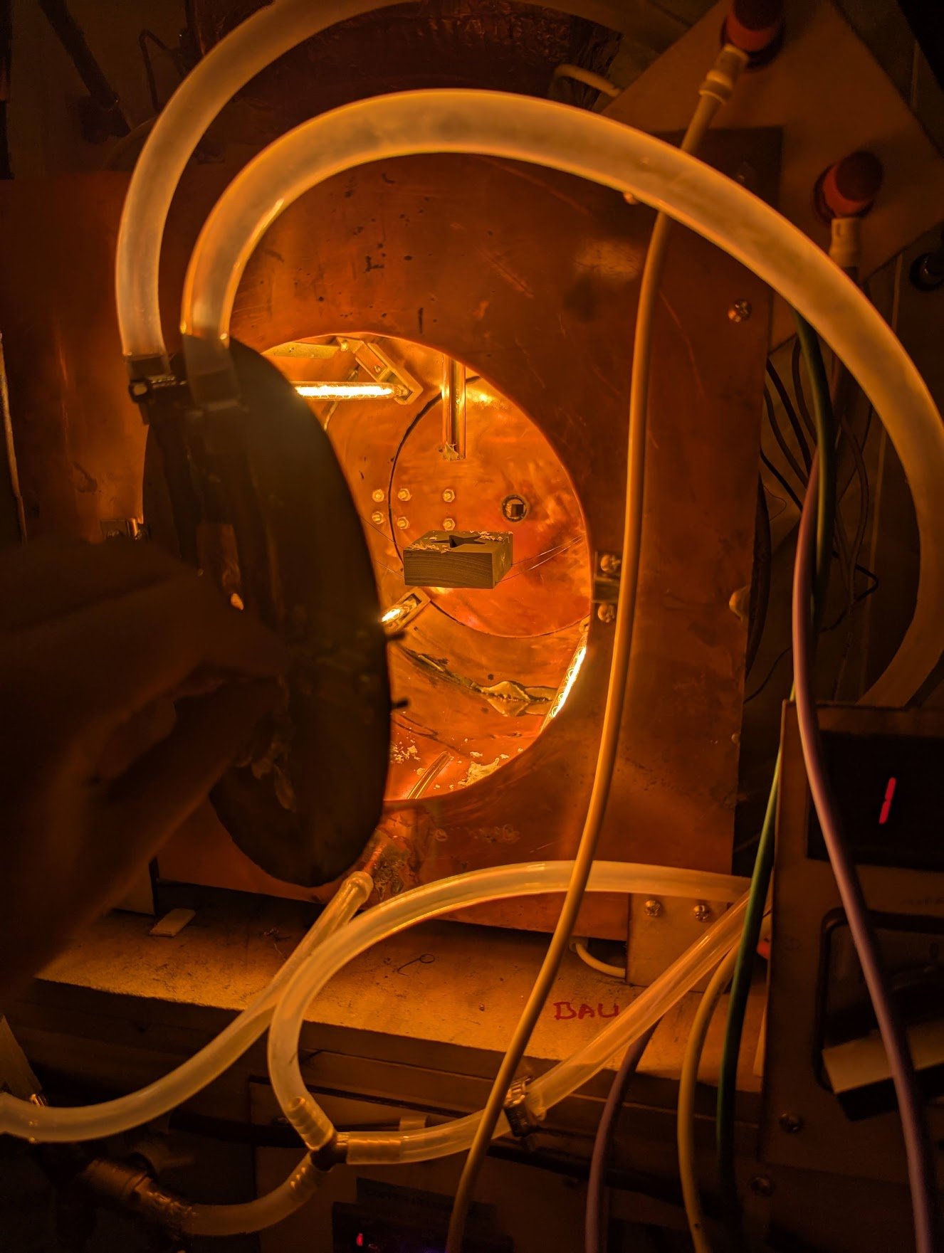
Infrared mirror ovenEvaluating the oven’s limitationsAnother view of the infrared oven during testing. The copper body became very hot, so the water cooling needed improvement. I was also concerned about the lamps overheating and about how to add radiant heat shielding around the central sample without blocking the light intended to heat it. These constraints limited the design’s usefulness for melting materials.
Personal project
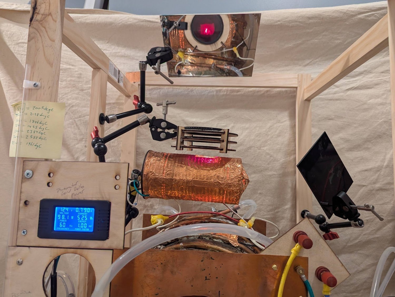
Infrared mirror ovenTrying to measure the platform’s temperatureThe pyrometer was aimed through a small opening in the top of the copper cylinder toward the graphite platform. This optical instrument compares a hot object’s glow with a reference filament. In these tests, the platform did not glow visibly enough to make a useful comparison, so the arrangement did not provide the intended temperature reading.
Personal project
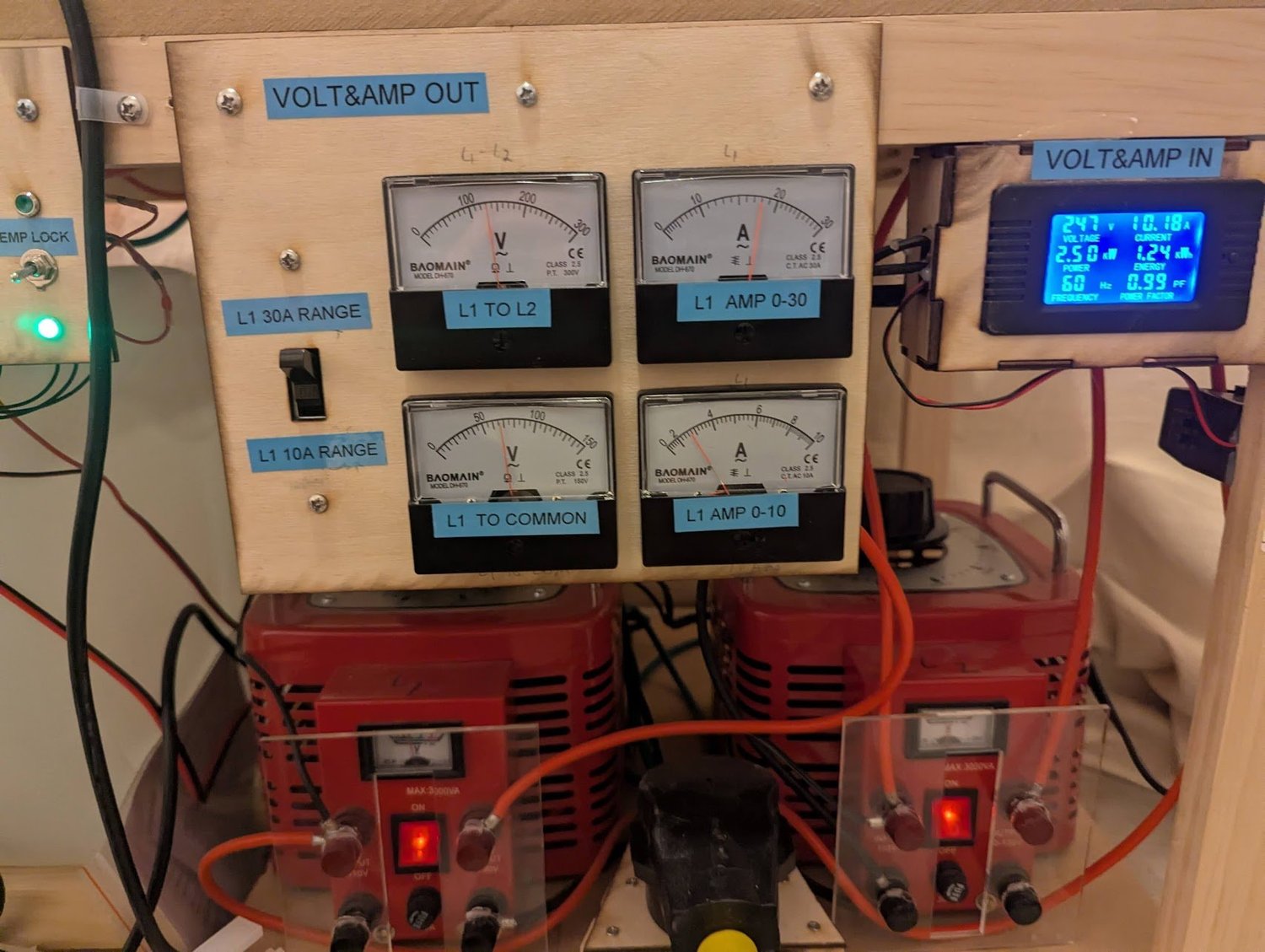
Infrared mirror ovenMonitoring power into the ovenAdded meters helped track the oven’s electrical conditions as I adjusted the Variacs. The measurements included combined and individual output voltages and current. The illuminated display on the right monitored input voltage, current, and power, making it easier to relate the oven’s behavior to the energy being supplied.
Personal project
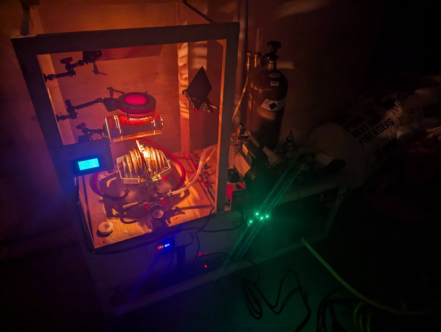
Copper clamshell furnace and pyrometerAn earlier copper clamshell furnaceTwo copper hemispheres form a hinged furnace chamber, with spiraling copper tubes carrying cooling water around each half. Electrical connections pass through the aluminum flange between them. Machining that large flange pushed the capacity of my milling machine. Above the chamber, the pyrometer’s glowing reference filament lights up the assembly.
Personal project
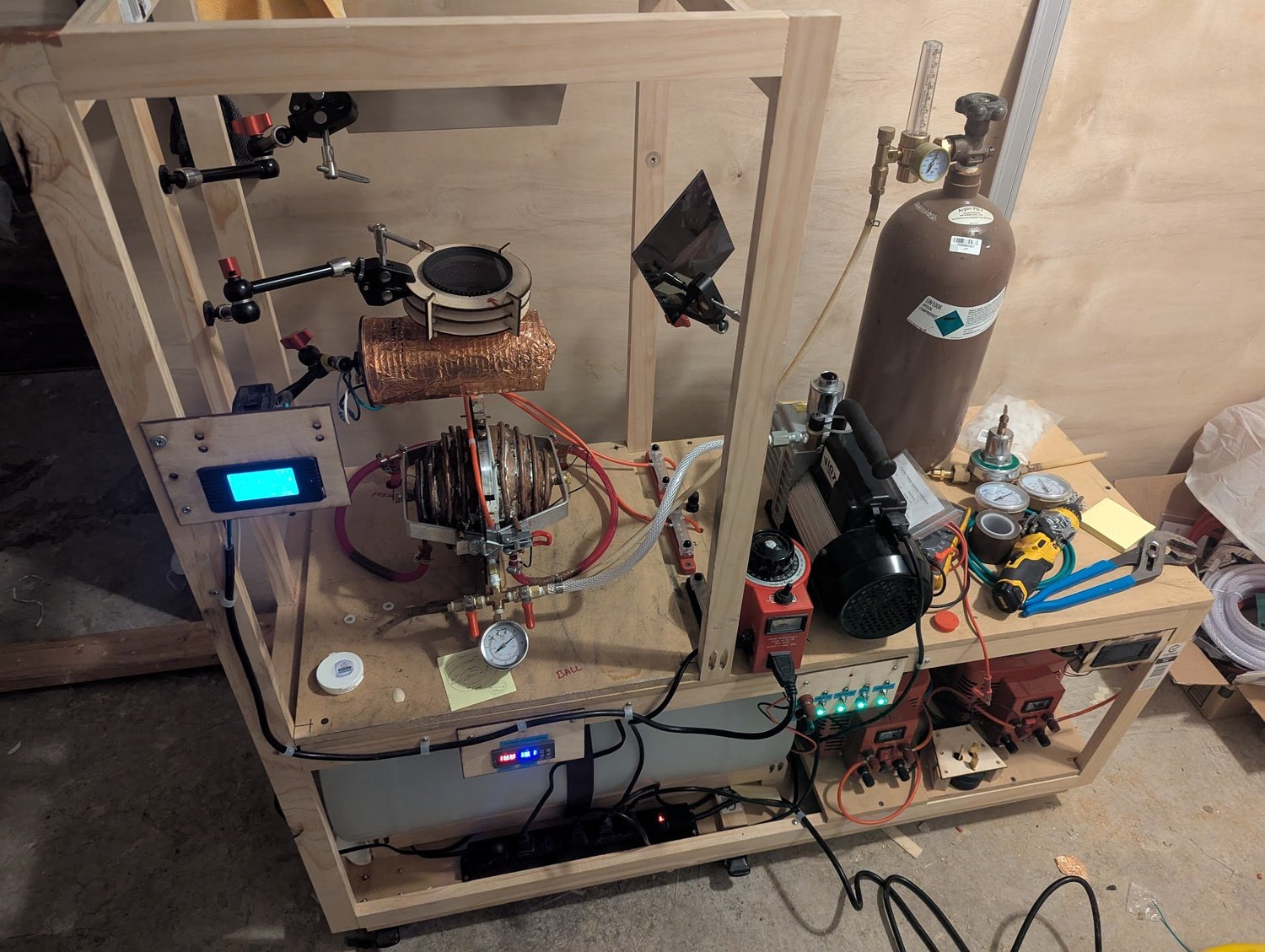
Copper clamshell furnace and pyrometerThe complete furnace setup in room lightThe same clamshell furnace with the room lights on. This wider view brings together the copper chamber, pyrometer, power equipment, and water-cooling system. It shows how the heating, measurement, and cooling parts of the experiment were arranged around one another.
Personal project
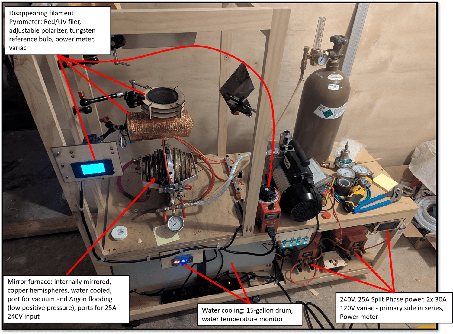
Copper clamshell furnace and pyrometerA guide to the furnace’s main systemsAn annotated overview identifying the furnace, optical pyrometer, electrical controls, and water-cooling equipment. The labels explain how the chamber and its supporting systems fit together, including the reference lamp and filters used to observe the heated material.
Personal project
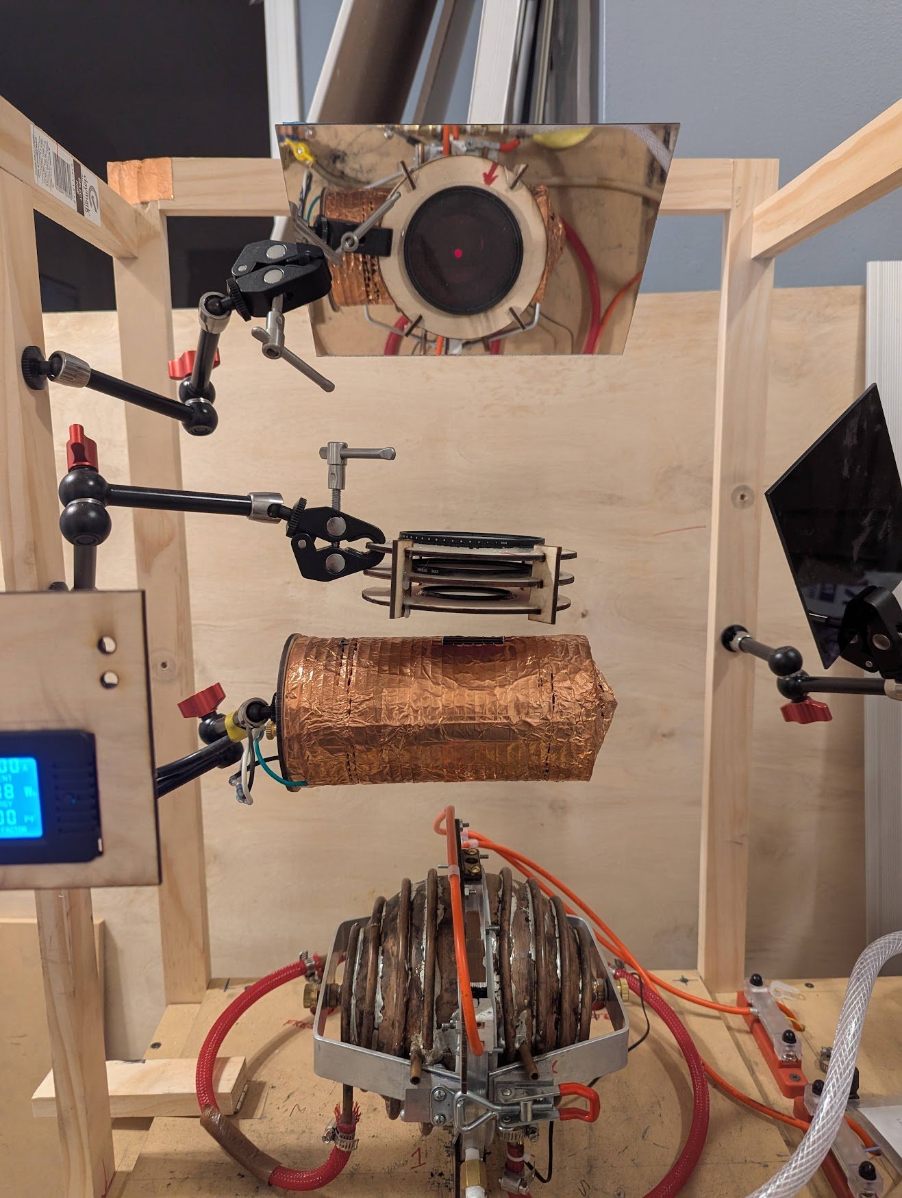
Copper clamshell furnace and pyrometerHow the disappearing-filament pyrometer worksThe pyrometer looks through a small opening in the furnace’s central flange. A reference filament appears in front of the hot target, and its brightness is adjusted until it blends into the target’s glow through a red filter. With calibration and an allowance for how strongly the target emits light, the reference setting can be used to estimate temperature. I built this setup to observe heated tungsten.
Personal project
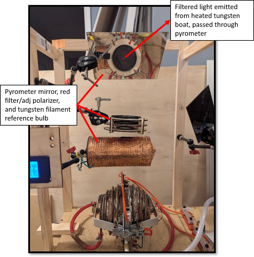
Copper clamshell furnace and pyrometerThe pyrometer’s optical pathThis annotated view identifies the tungsten reference lamp, red filter, adjustable polarizer, and viewing mirror. The filter selects red light for the brightness comparison, while the polarizer adjusts the transmitted brightness. A first-surface mirror redirects the view to the side, allowing observation without standing directly over the furnace.
Personal project
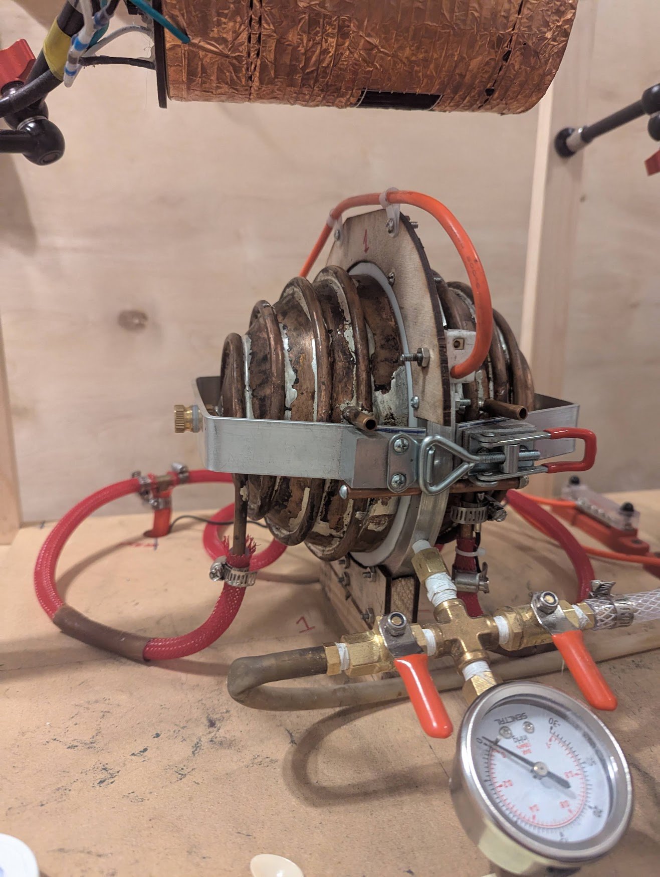
Copper clamshell furnace and pyrometerCooling, plumbing, and chamber hardwareThe copper furnace halves, cooling pipes, and aluminum clamping structure. The chamber connections used threaded plumbing fittings with PTFE (Teflon) thread-seal tape, red-handled ball valves, and a mechanical gauge indicating vacuum relative to atmospheric pressure. This was convenient hardware for an early experiment, but the plumbing valves and connections were not designed for vacuum service—a limitation I addressed in later designs.
Personal project
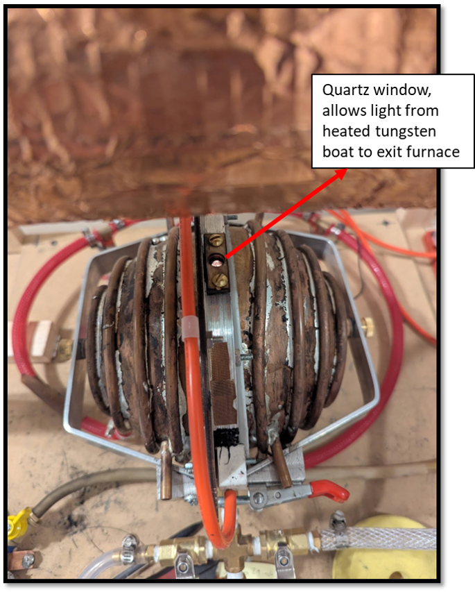
Copper clamshell furnace and pyrometerA quartz window for the pyrometerA small quartz window installed in an opening through the top of the aluminum flange. It provided an optical path out of the furnace so the pyrometer could observe the heated material inside while the chamber remained closed.
Personal project
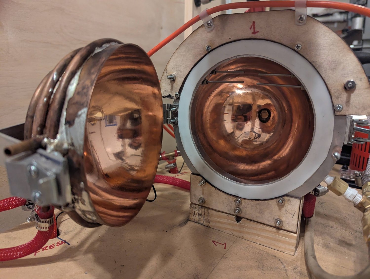
Copper clamshell furnace and pyrometerThe polished chamber and its feedthroughsThe polished copper interior was intended to reflect light back toward the sample. Four tungsten rods passed through the flange: two to suspend the crucible and two to connect the heating filament. Ceramic pieces positioned the rods, while silicone sealed the penetrations. These early trials exposed practical problems with fragile filaments, repeatable attachments, and keeping seals away from excessive heat, which shaped later feedthrough designs.
Personal project
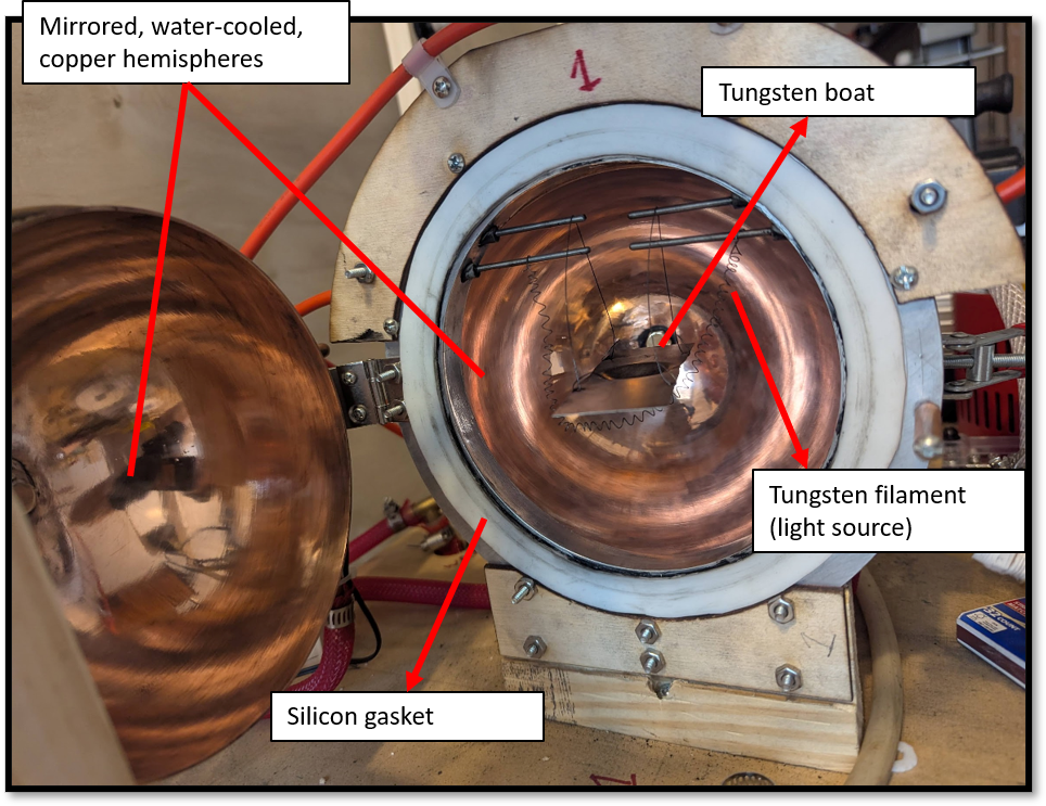
Copper clamshell furnace and pyrometerThe suspended tungsten boat and heaterAn annotated view of the tungsten boat—the small tray holding the sample—suspended on tungsten wires beside the heating filament. Gaskets sealed the chamber, and the vacuum was intended to reduce heat transfer through the surrounding gas. I also used argon to displace air. Balancing heat loss, oxygen control, and filament life became a central challenge of this furnace.
Personal project
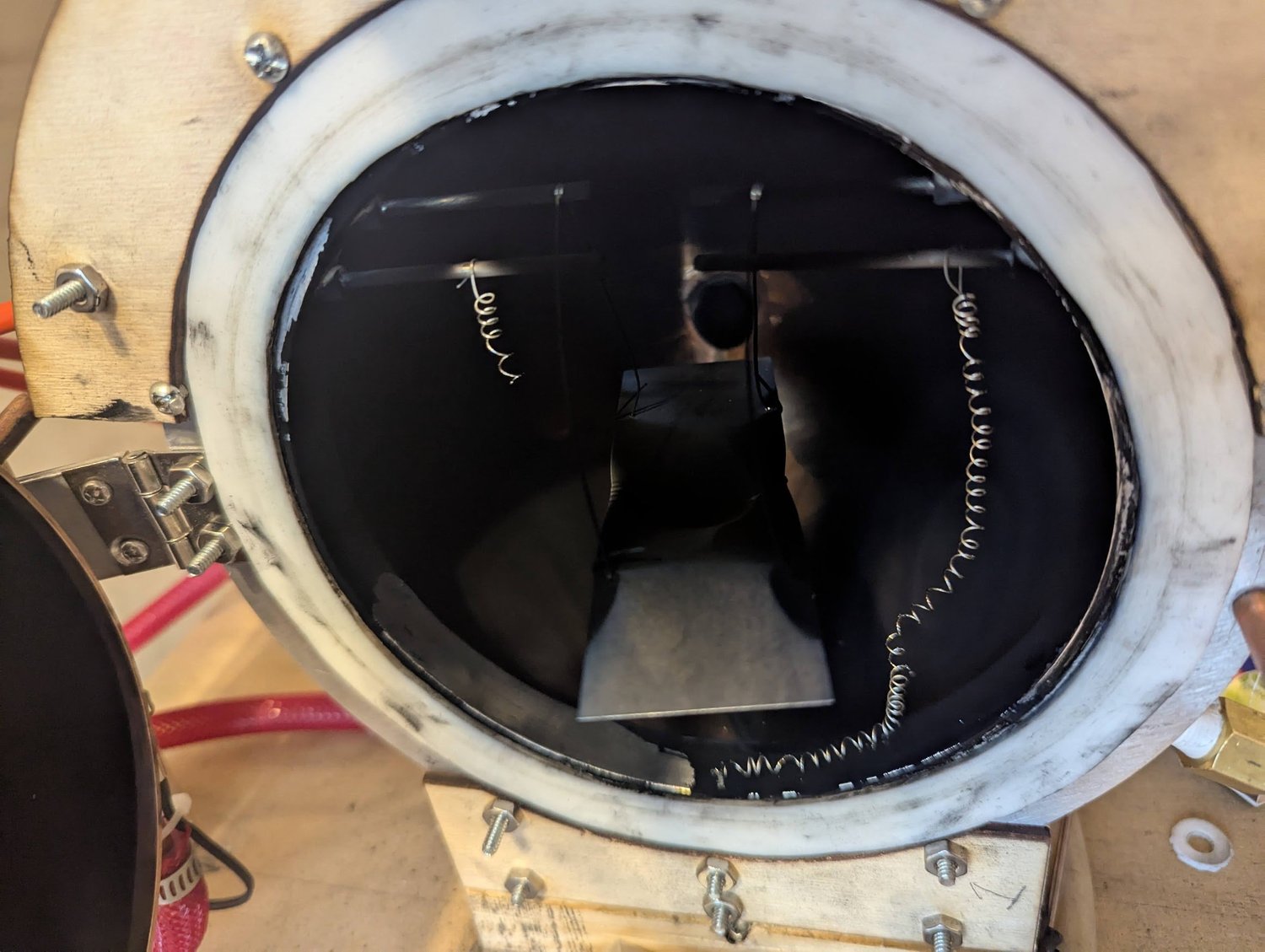
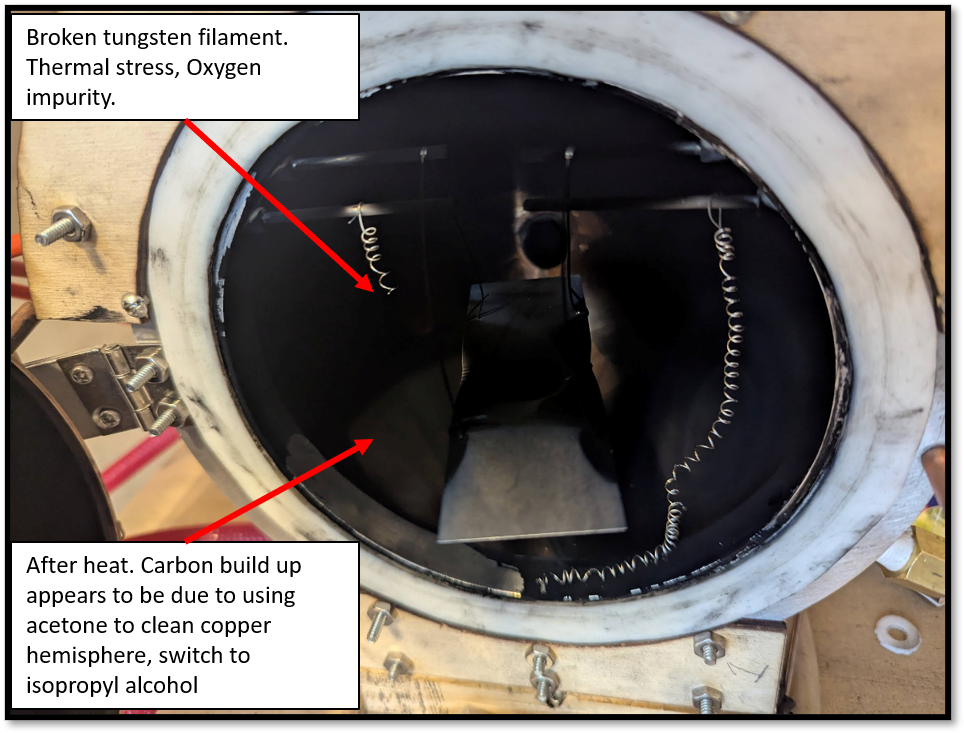
Copper clamshell furnace and pyrometerA failed filament and darkened chamberA broken filament and heavy dark deposits after a heating trial. The copper walls had started out polished and reflective. I came to see residual oxygen attacking the thin filament as a major problem, alongside the filament’s fragility and the difficulty of making durable electrical connections.
Personal project
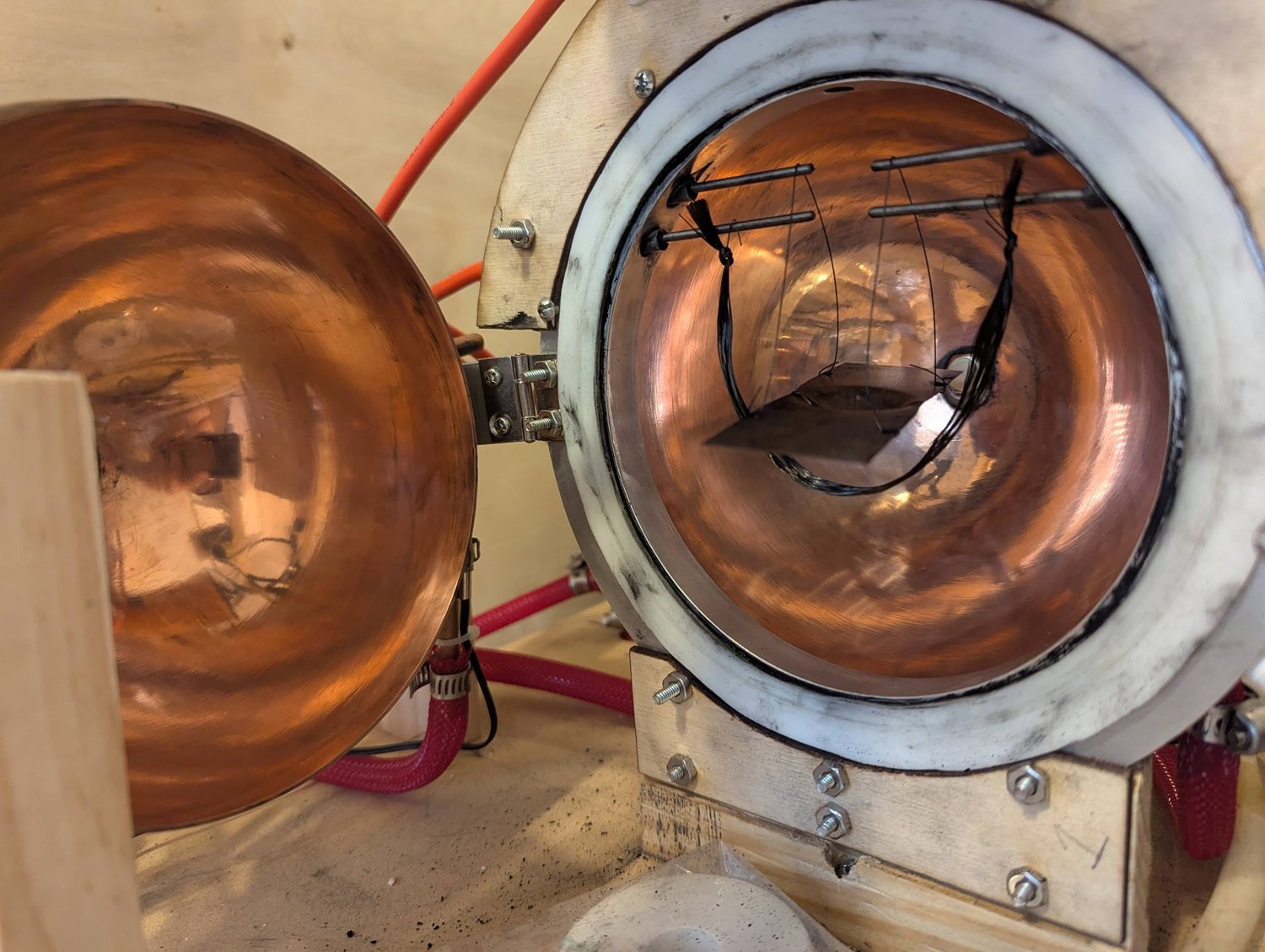
Copper clamshell furnace and pyrometerInvestigating the black depositsMy original annotations record an early suspicion that cleaning-solvent residue might be responsible for the black coating. That was a working hypothesis: I did not establish the deposit’s composition or confirm that the solvent caused it. The image also documents a broken tungsten filament from the same series of tests.
Personal project
Copper clamshell furnace and pyrometerTrying a conductive carbon filamentA trial using conductive carbon or graphite material as the heater. I no longer recall the exact material, but it failed quickly. The simple attachment around the feedthrough rods also highlighted the need for a more durable and repeatable way to connect the heating element.
Personal project
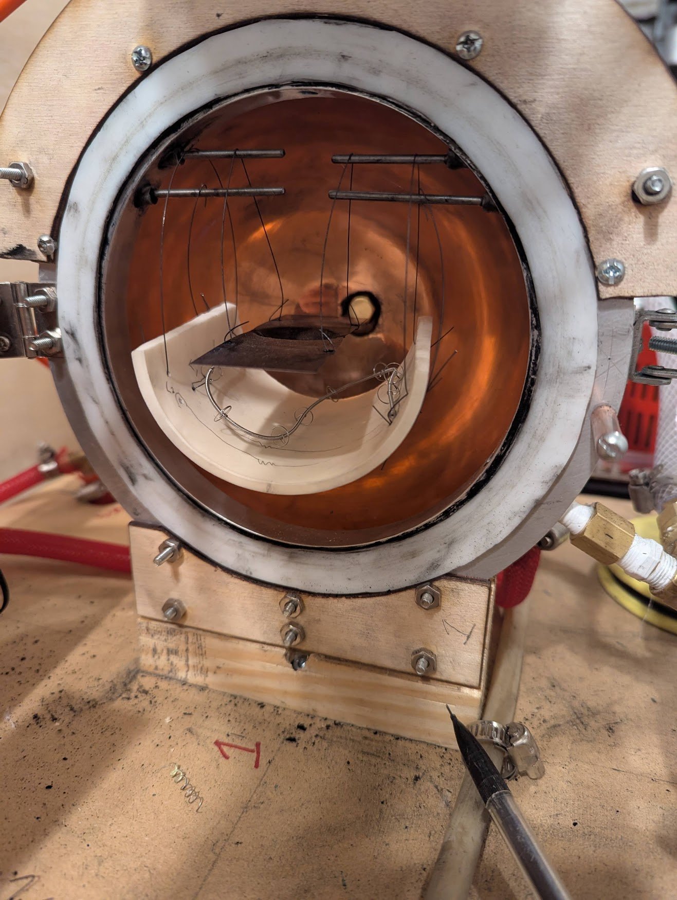
Copper clamshell furnace and pyrometerSupporting a salvaged tungsten filamentA delicate tungsten filament recovered from a halogen lamp, supported in a magnesium-oxide half-cylinder. The ceramic cradle was intended to support the filament mechanically while it served as the furnace’s heat source.
Personal project
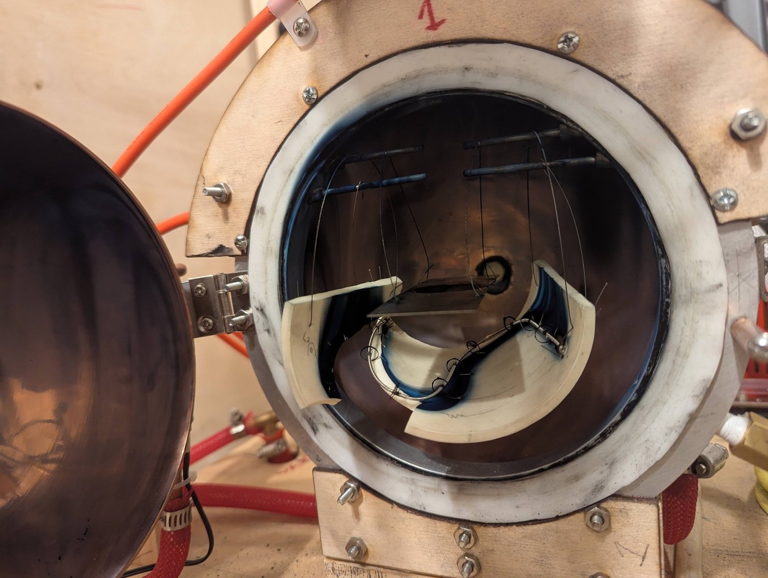
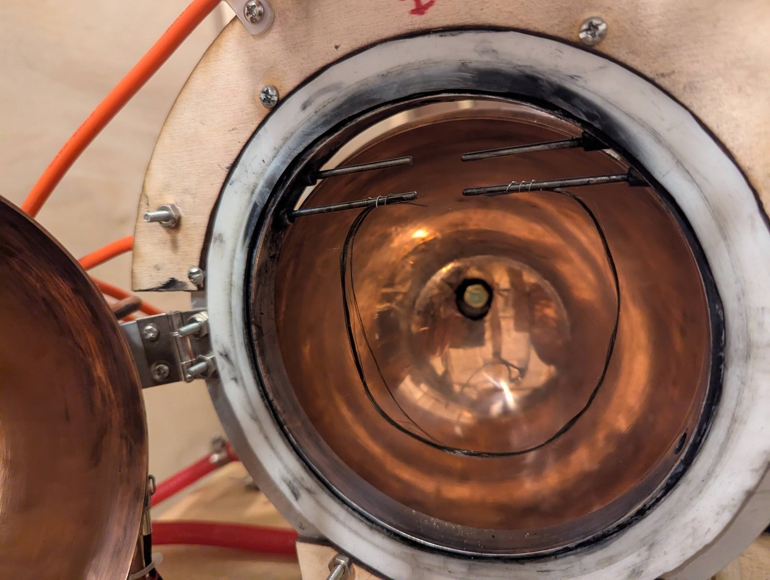
Copper clamshell furnace and pyrometerA cracked support and another filament failureThe magnesium-oxide support cracked, and the filament failed during this trial. Blue deposits appeared around the filament, which I interpreted as tungsten oxide. The result showed that both the support arrangement and the filament’s operating environment still needed improvement.
Personal project
Copper clamshell furnace and pyrometerAnother carbon-based heater experimentAnother trial with a carbon-fiber or graphite-type heating material. This element also broke during testing. I was comparing several possible heater materials while trying to understand the recurring failures; I no longer recall the exact grade used here.
Personal project
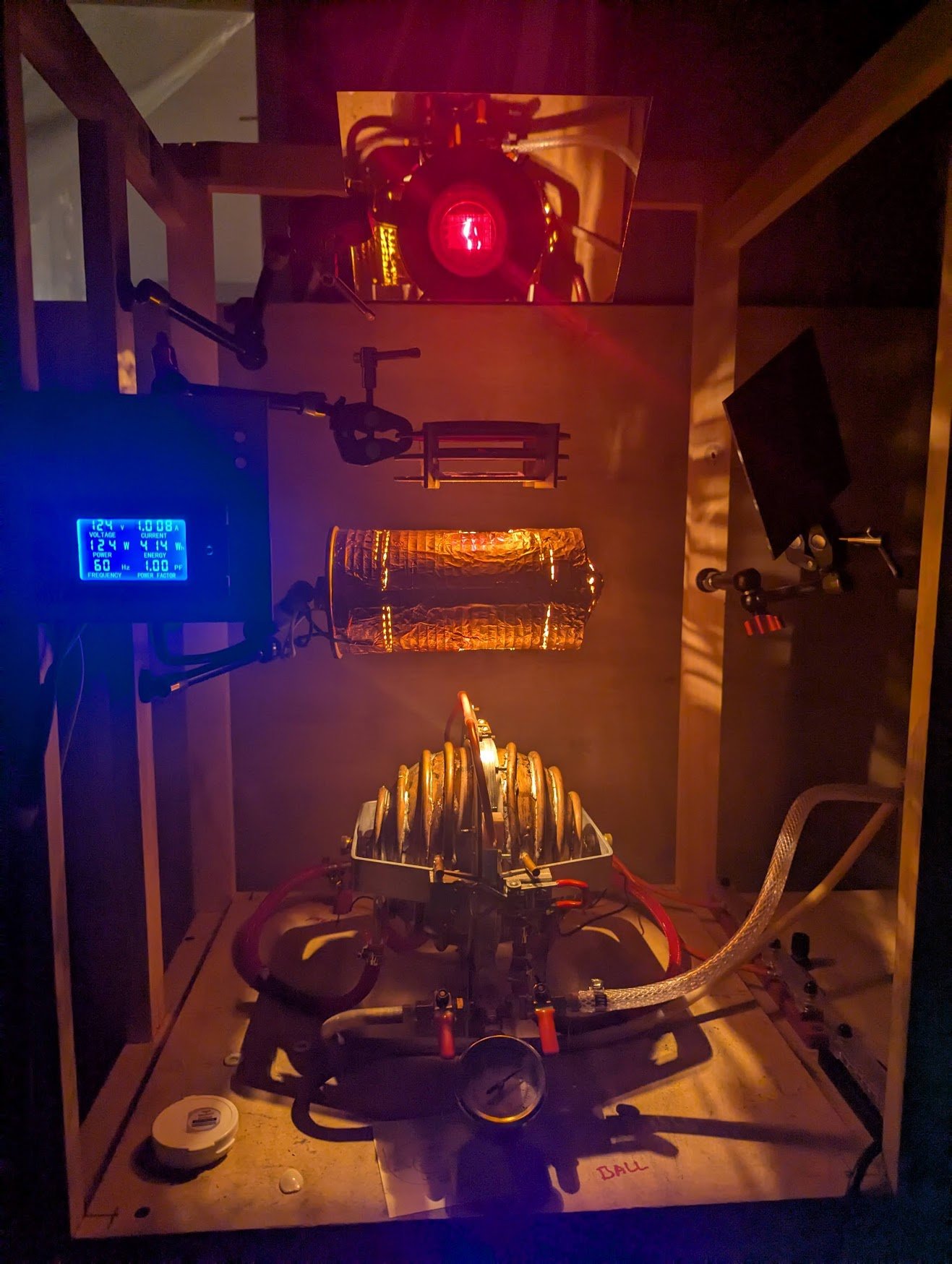
Copper clamshell furnace and pyrometerReading the pyrometer’s reference-lamp powerThe illuminated meter on the left shows power supplied to the pyrometer’s 200-watt reference bulb. A Variac, outside this view, adjusted the lamp’s brightness. After matching the filament to the hot target, I used a separate lookup graph relating reference-lamp power to an estimated target temperature.
Personal project
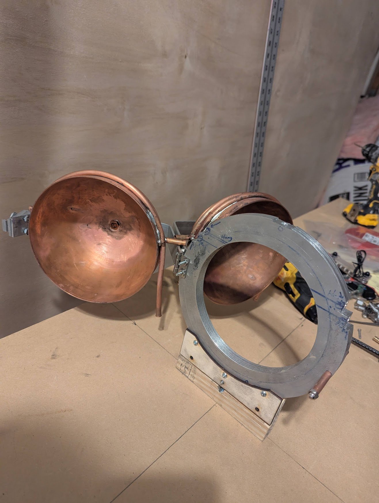
Copper clamshell furnace and pyrometerThe copper furnace under constructionAn early construction view of the clamshell furnace. The copper surfaces had not yet been polished, and several components were still missing. It shows the assembly before the reflective finish and the later heating and measurement experiments.
Personal project
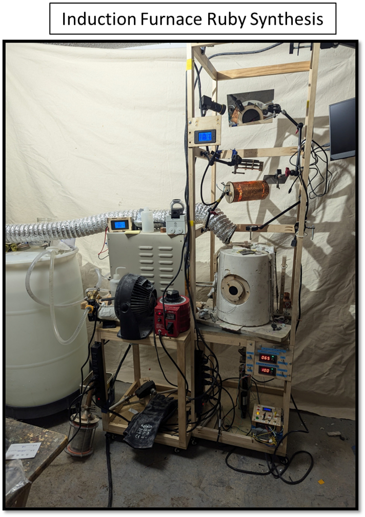
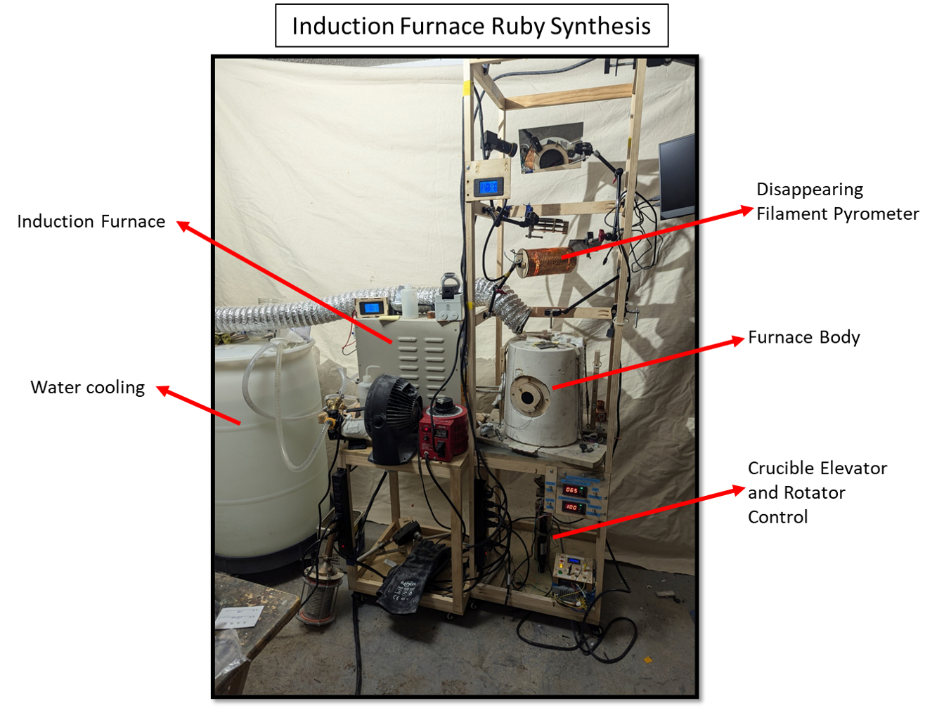
Induction-heated ruby experimentsAn induction furnace for ruby-growth experimentsAn earlier attempt to melt ruby feedstock using induction heating. The setup brought together the furnace, power equipment, cooling, and an optical pyrometer. I never achieved a full melt with this version, but the project included several mechanisms and measurement tools that I could carry into later experiments.
Personal project
Induction-heated ruby experimentsThe induction-furnace systems at a glanceAn overview of the induction-furnace setup, with arrows highlighting its main assemblies. The furnace and its supporting power, cooling, and measurement equipment were arranged together so I could investigate the heating process and monitor the experiment.
Personal project
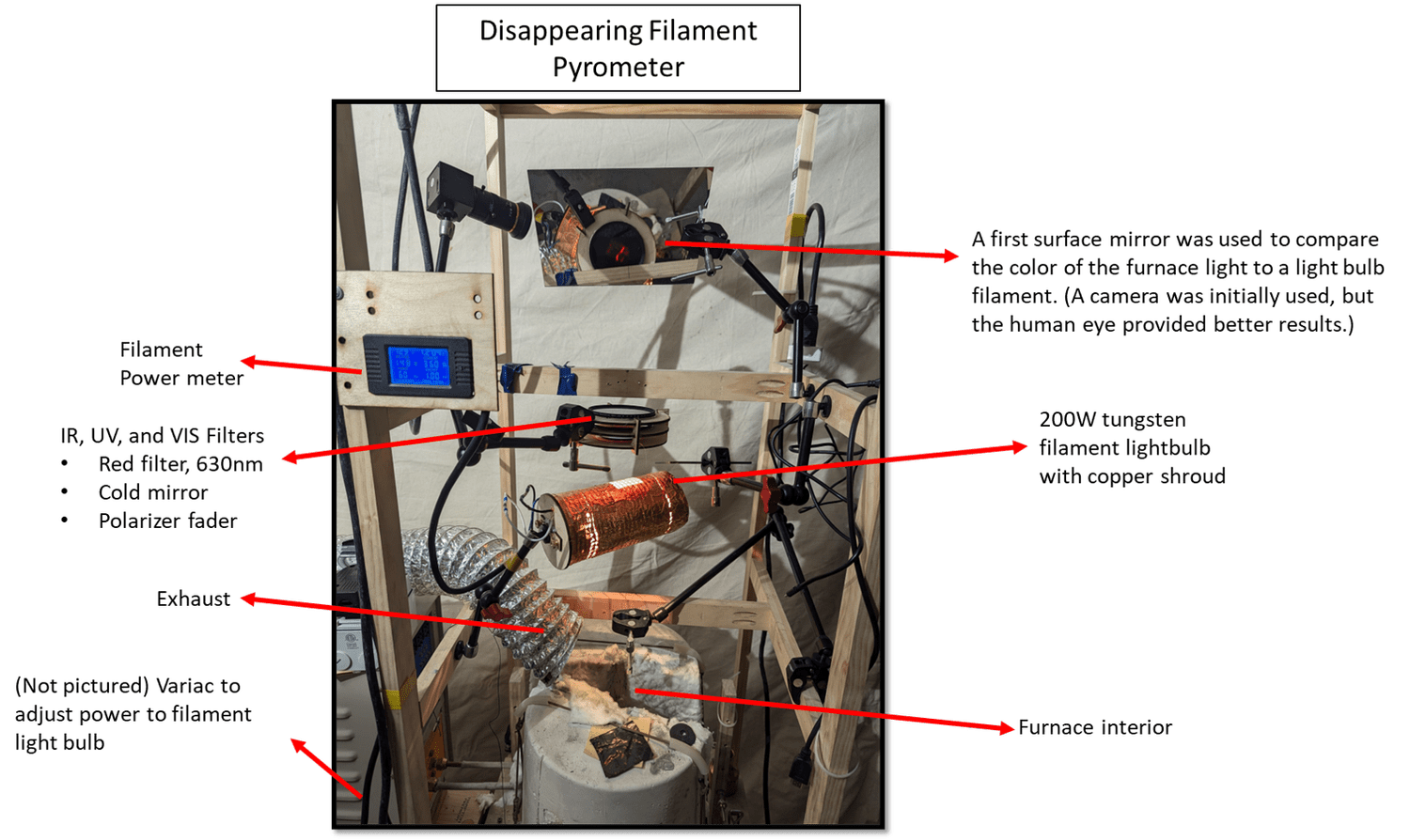
Induction-heated ruby experimentsThe pyrometer on the induction furnaceAn annotated view of the disappearing-filament pyrometer used with the induction furnace. It identifies the reference lamp, lamp-power meter, optical filters, and viewing mirror. The instrument compared the target’s glow with an adjustable reference filament to estimate temperature.
Personal project
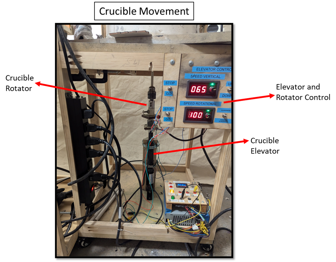
Induction-heated ruby experimentsA mechanism to lift and rotate the crucibleThe elevator and rotation mechanism I built to move the crucible as the feedstock melted. Because this furnace never produced a full melt, I did not use the mechanism during the intended melting process. I kept the assembly for possible use in a later project.
Personal project
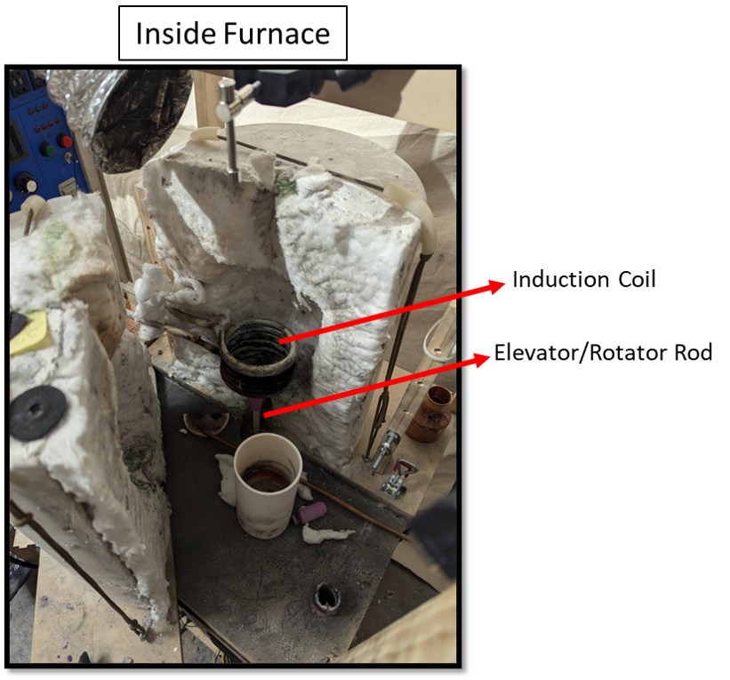
Induction-heated ruby experimentsHow the nested crucible heated the sampleInside the induction coil, a graphite puck heated an adjacent tungsten plate, which supported the alumina and chromium-oxide feedstock. An inverted smaller crucible covered the feedstock, forming walls and a ceiling over the tungsten floor. The surrounding crucible assembly was insulated with high-temperature ceramic wool. The aim was to concentrate heat in the sample while keeping it enclosed.
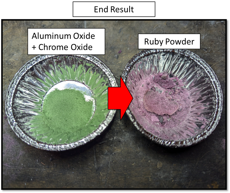
Personal project
Induction-heated ruby experimentsA fragile result from the induction furnaceThe heating trials produced a powdery material that I identified as ruby, but it broke apart easily by hand. The particles had not bonded into a strong, dense body. I wondered whether more heating time might help, but the many assembly steps made each trial slow and tedious, so I moved on to other furnace designs.
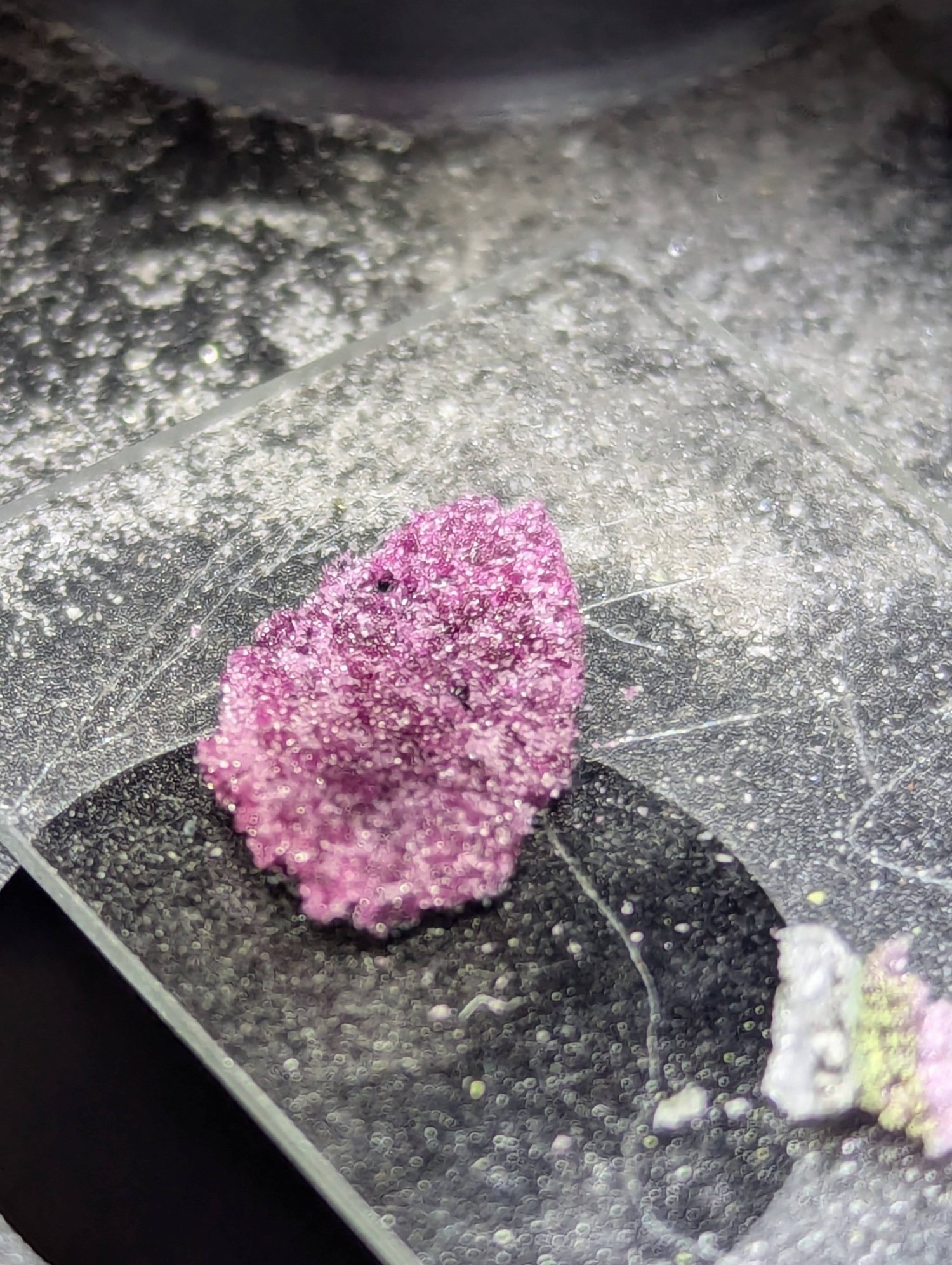
Personal project
Induction-heated ruby experimentsA larger fragment from the heating trialOne of the larger pieces recovered from the induction-heating process. Although the material held together enough to remove as a fragment, it remained fragile. It was an intermediate result in the effort to turn alumina and chromium oxide into a consolidated ruby sample.
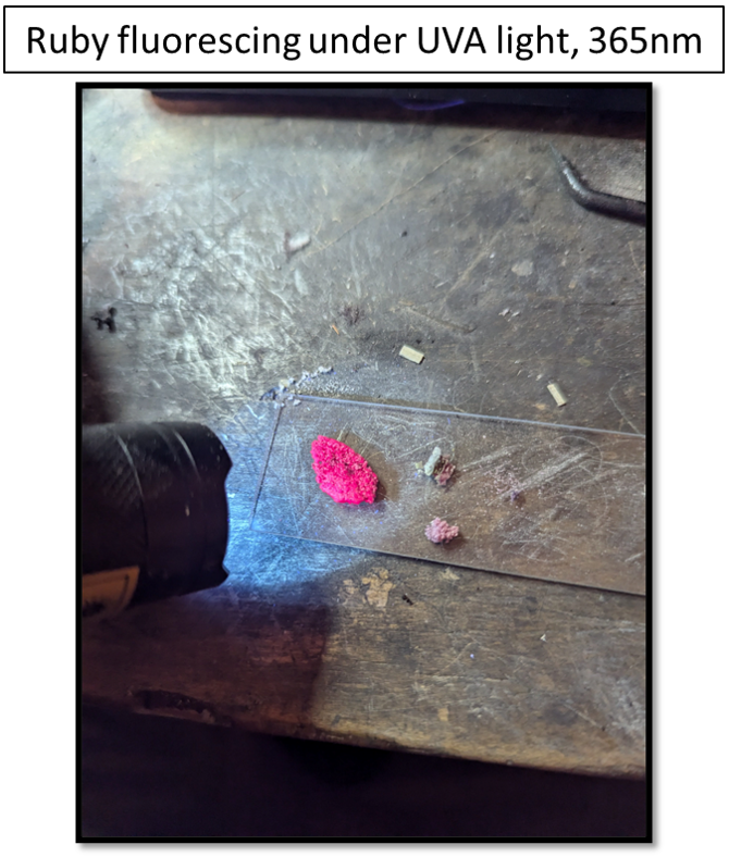
Personal project
Induction-heated ruby experimentsChecking the sample under ultraviolet lightThe sample fluorescing under ultraviolet light. I used this glow as a quick visual check and took it as encouraging evidence of ruby formation in the heated feedstock. These images document the fluorescent response of the experimental material.
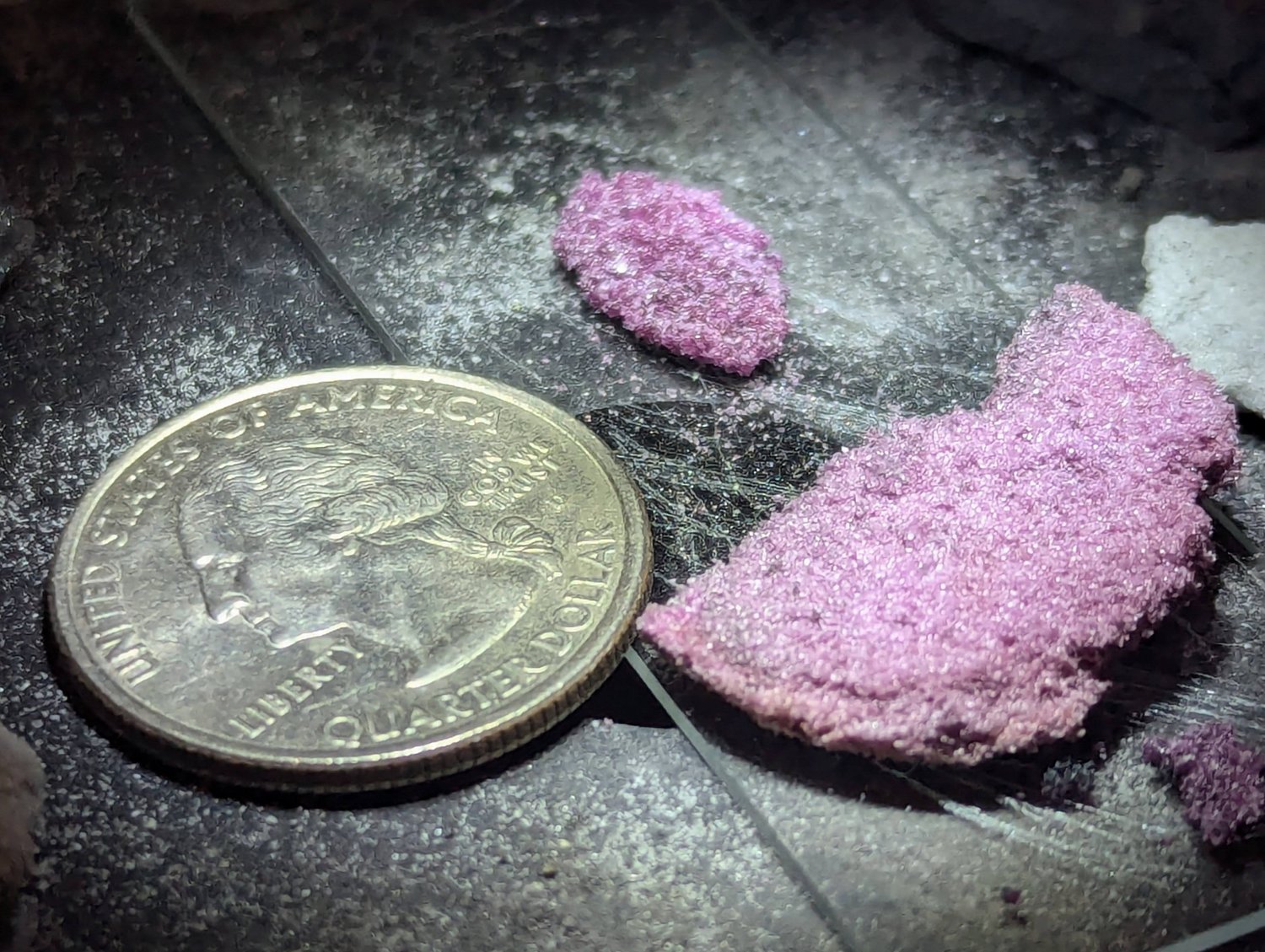
Personal project
Induction-heated ruby experimentsThe sample beside a quarterA piece of the recovered material beside a U.S. quarter for scale. This records the size of the sample produced by the nested-crucible induction experiment.
Personal project
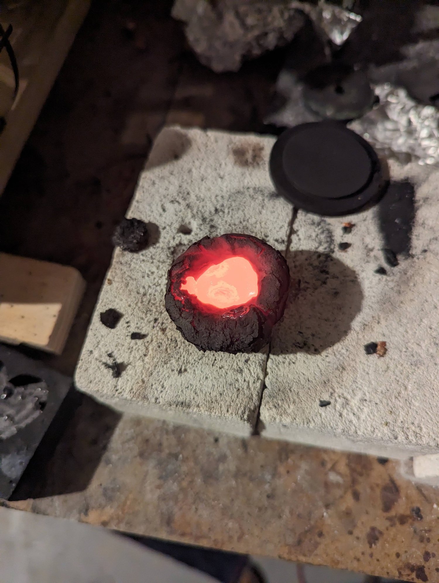
Homemade carbon cruciblesExperiments with homemade carbon cruciblesI explored making lightweight carbon shapes from organic mixtures heated with very little oxygen, a process called pyrolysis. The resulting pieces could be fragile, but I tried them as crucibles and insulation. I also experimented with graphite-flake additions, hoping to make the material heat directly by induction, without establishing a successful result for that approach.
Personal project
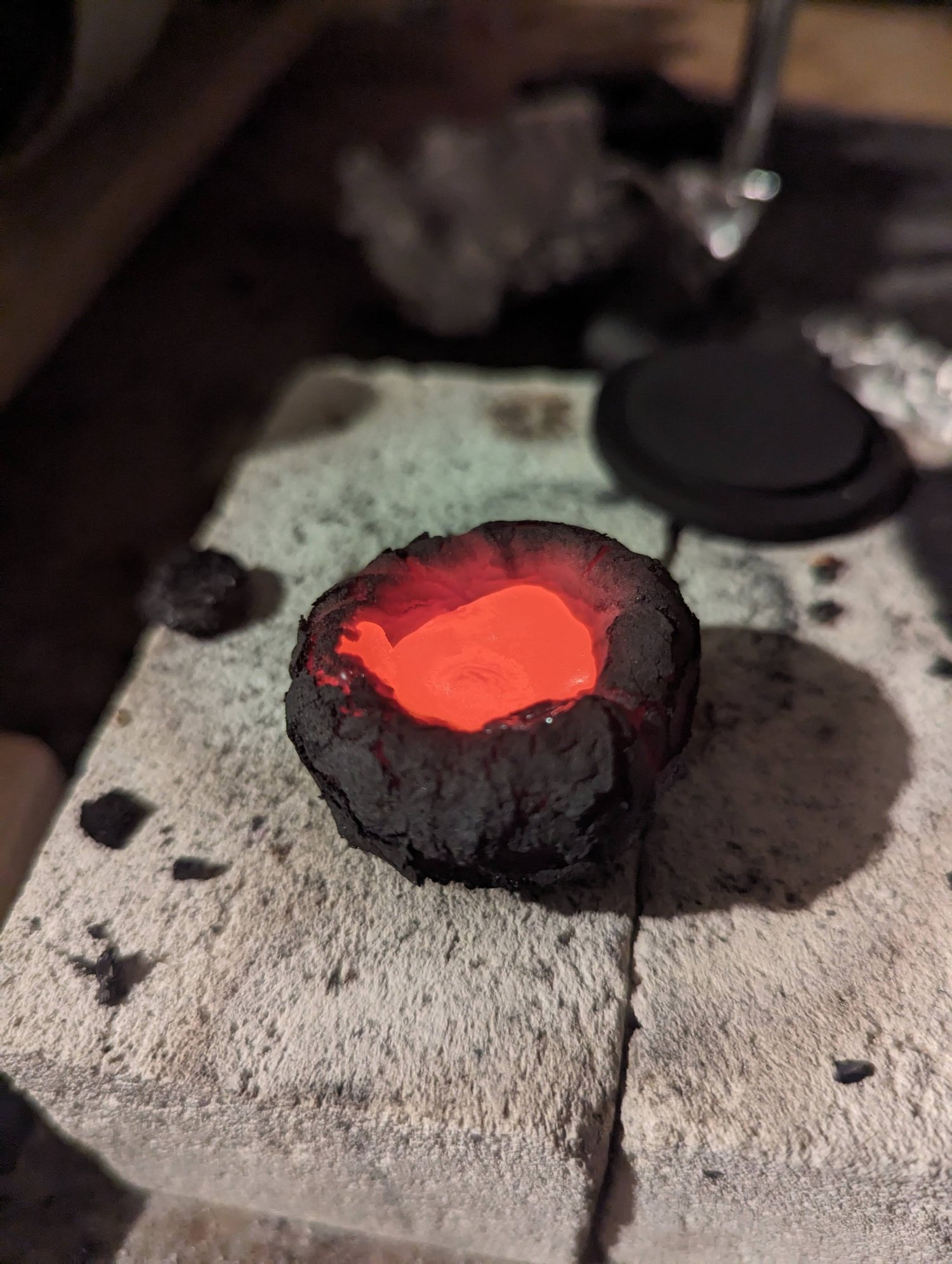
Homemade carbon cruciblesMelting copper in a test crucibleA test in which small copper-wire offcuts melted together into a single bead in one of the crucibles, heated with a gas torch. Watching the bright, shifting surface of the molten copper was a memorable part of these material experiments.
Personal project
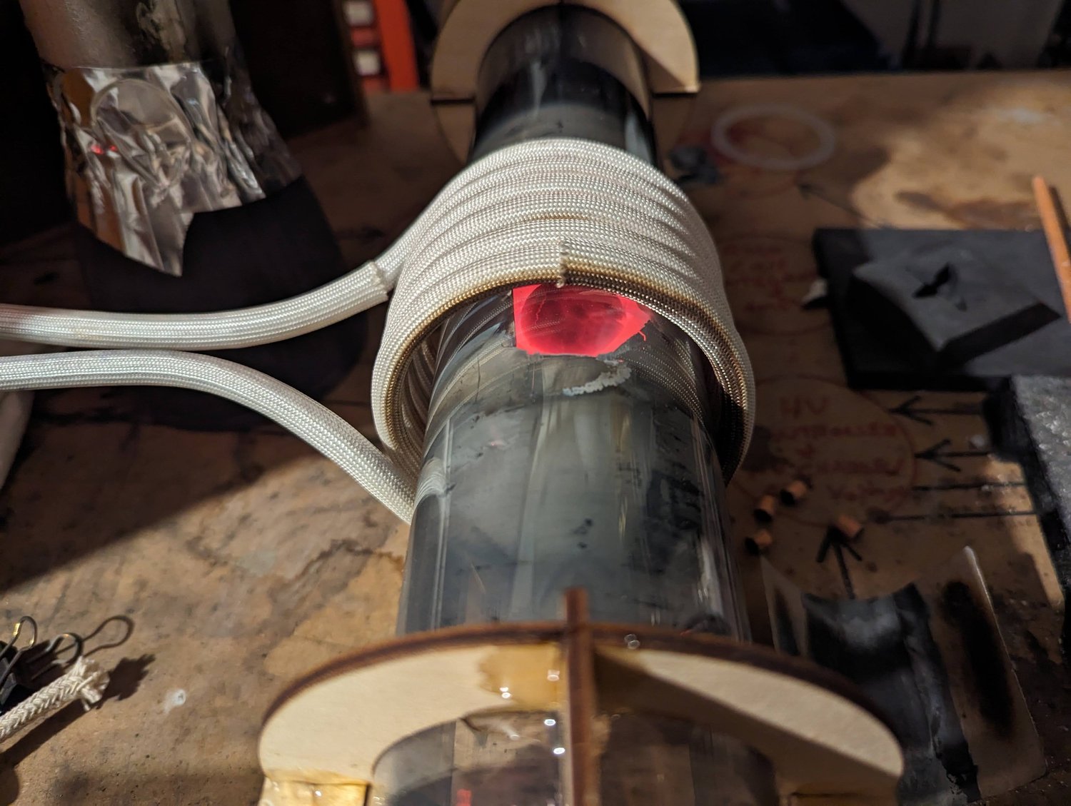
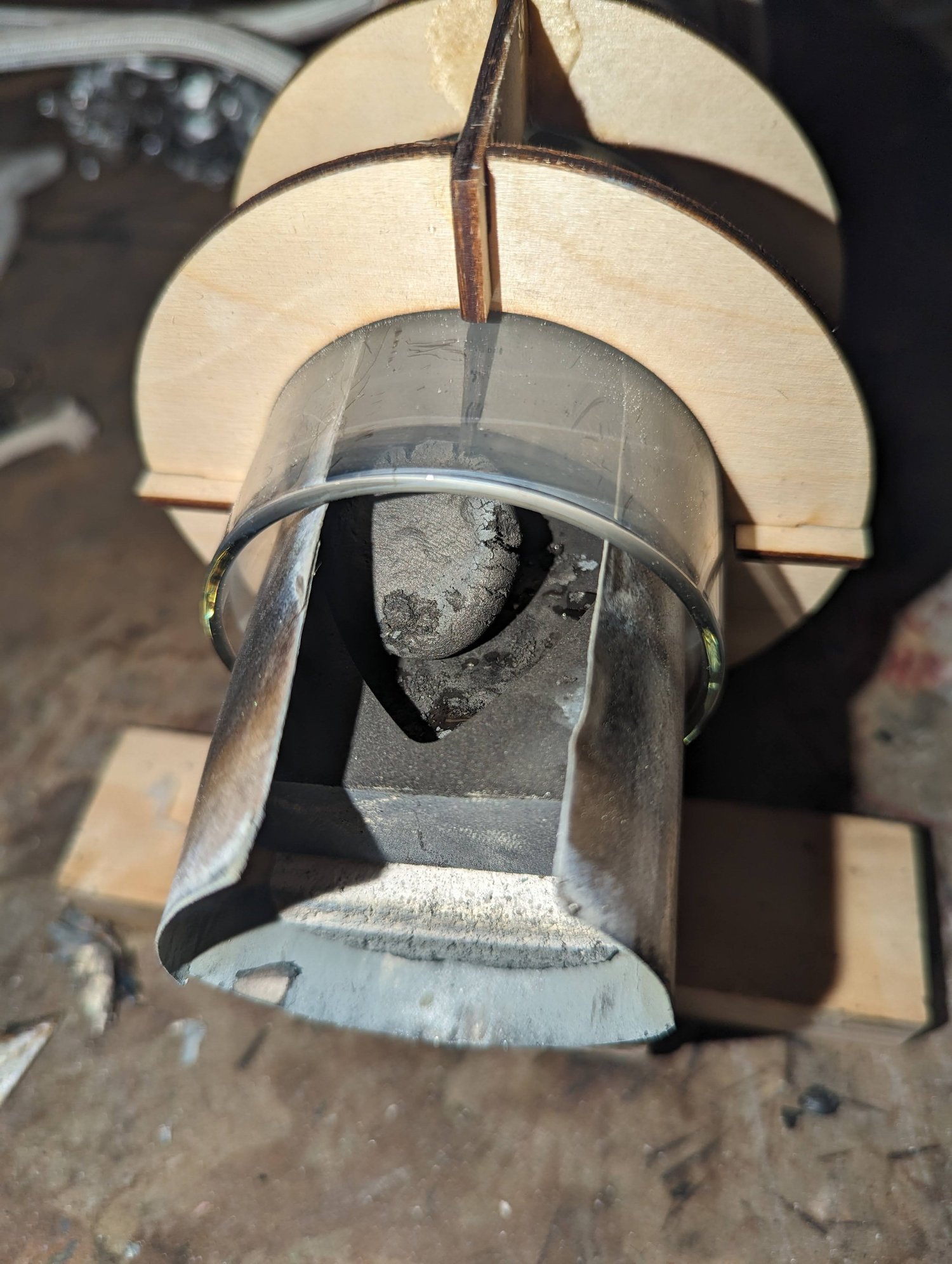
Quartz-tube induction furnaceA quartz-tube induction furnace experimentA quartz tube held in the center of the induction coil, with a graphite platform on a firebrick support inside. The platform could slide in and out for loading samples, and the graphite was the material heated by induction. The tube eventually cracked. I considered the assembly too fragile and abandoned this design.
Personal project
Quartz-tube induction furnace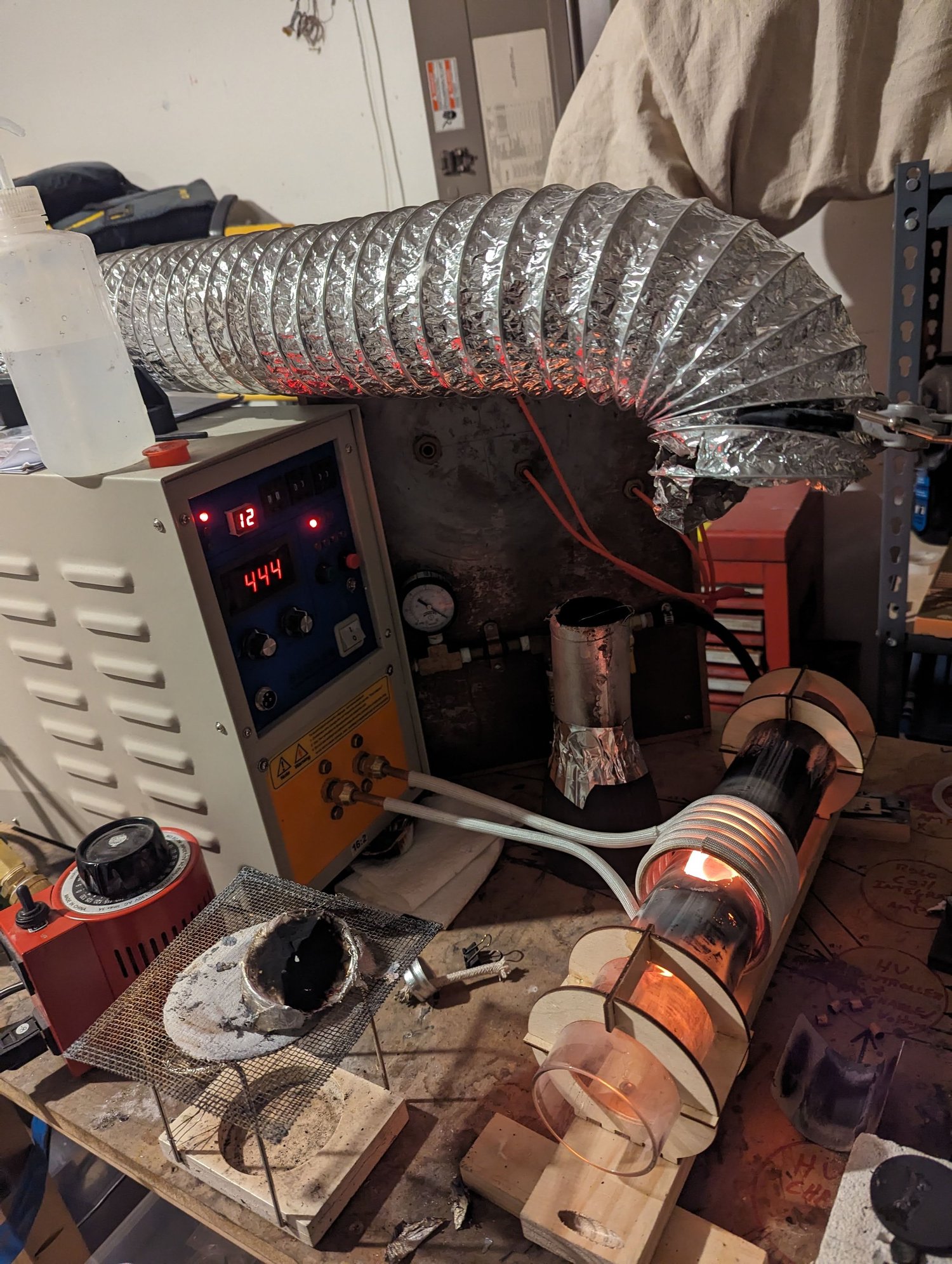
Personal project
Quartz-tube induction furnace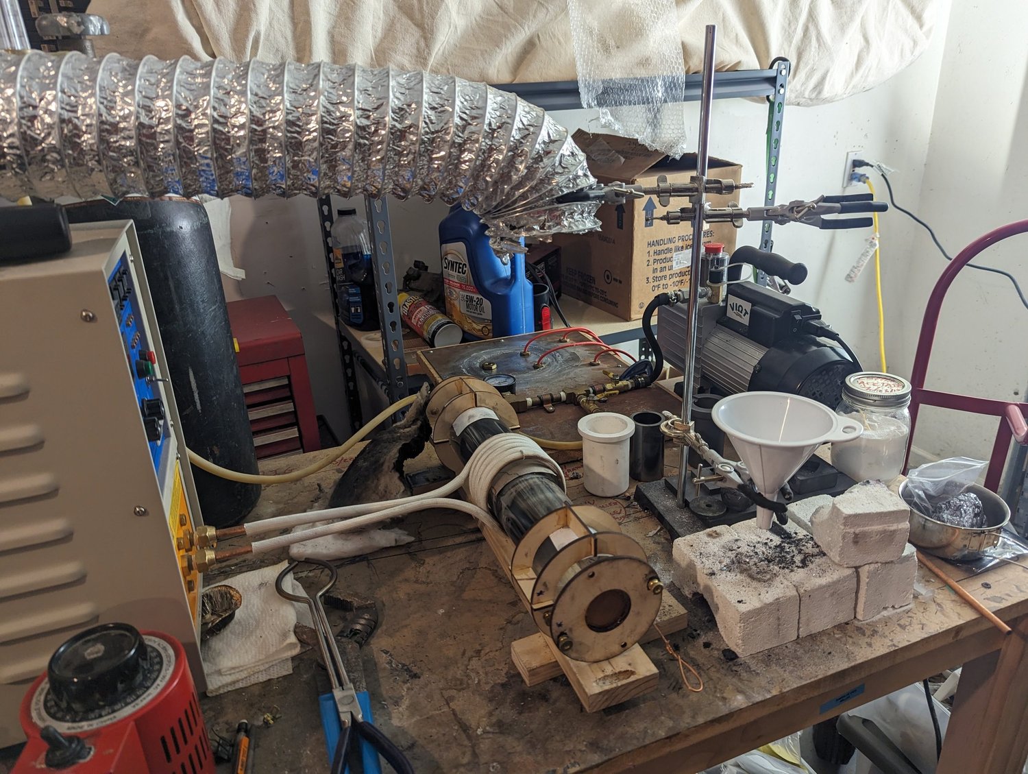
Personal project
Quartz-tube induction furnaceThe quartz-tube furnace setupAnother view of the quartz-tube experiment, showing more of the surrounding equipment. I recall sealing the tube at both ends and operating it under vacuum. After the quartz cracked, I decided the design was too fragile for the work I wanted to do.
Personal project
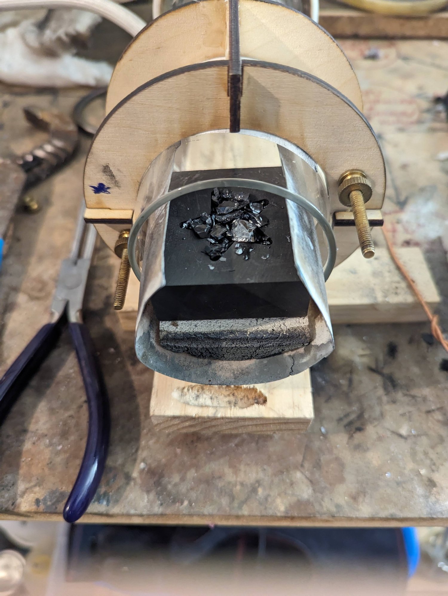
Quartz-tube induction furnaceTrying a silicon samplePolycrystalline silicon chunks loaded for an exploratory heating trial. I wanted to see whether this setup could remelt them, but I did not establish a successful melt and suspected the furnace could not reach the temperature needed.
Personal project
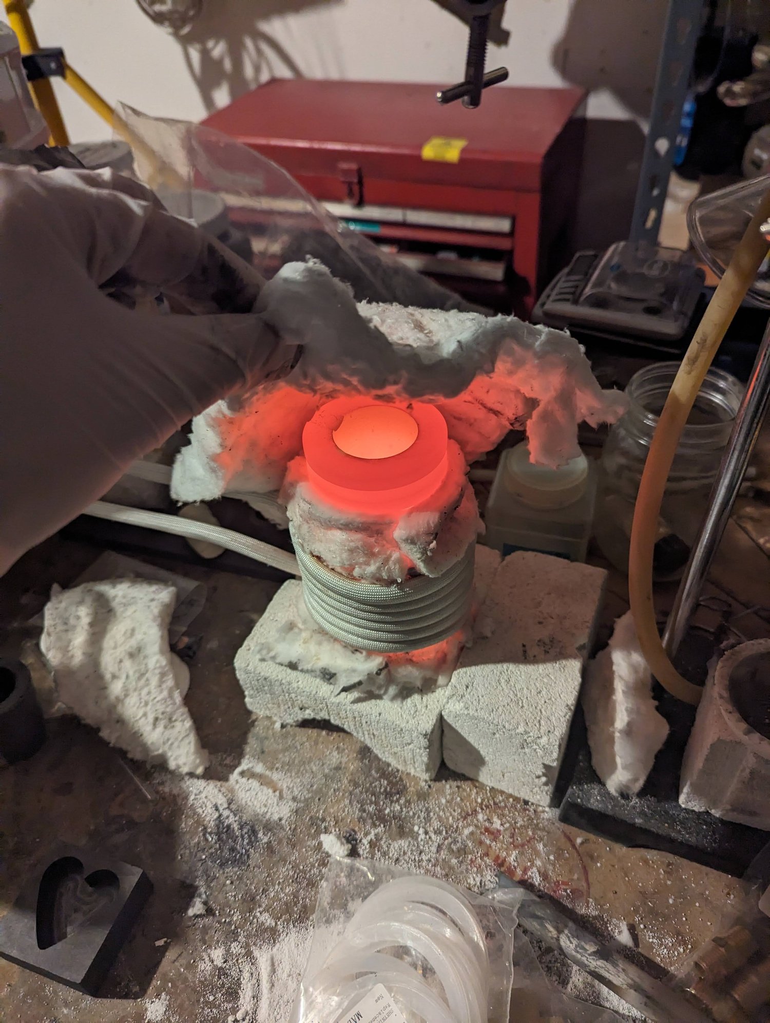
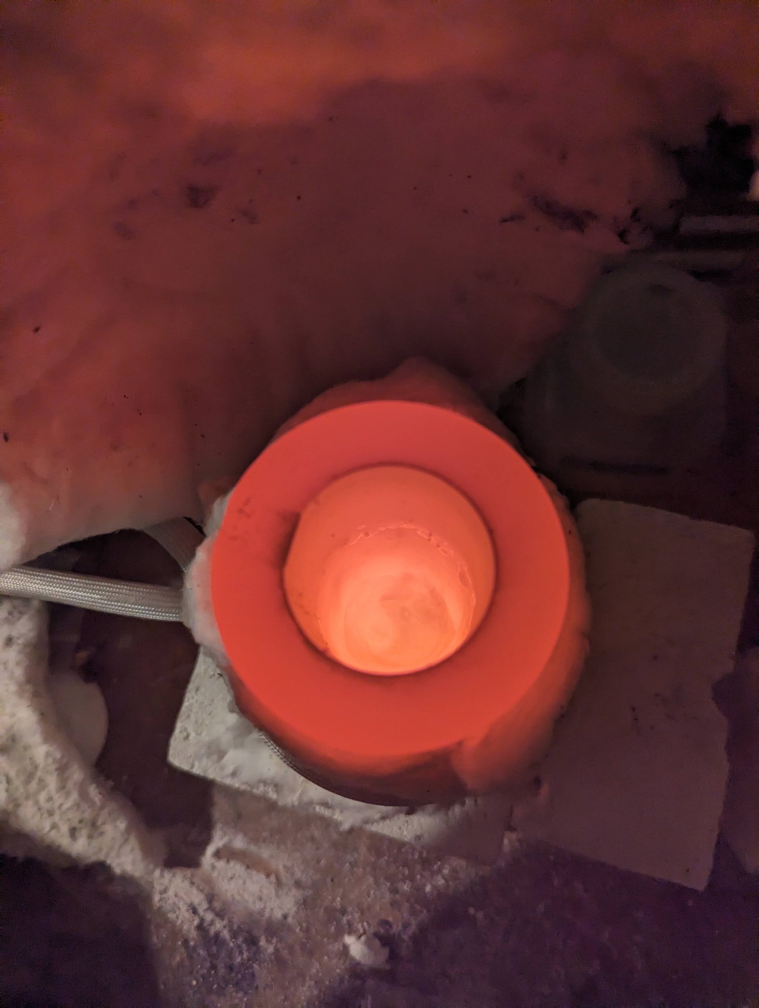
Quartz-tube induction furnaceHeating a graphite mold by inductionA graphite mold on a firebrick support during an induction-heating experiment. The graphite glowed orange, showing how readily this arrangement heated it. I used the hot graphite as a container and heat source for small melting trials.
Personal project
Quartz-tube induction furnace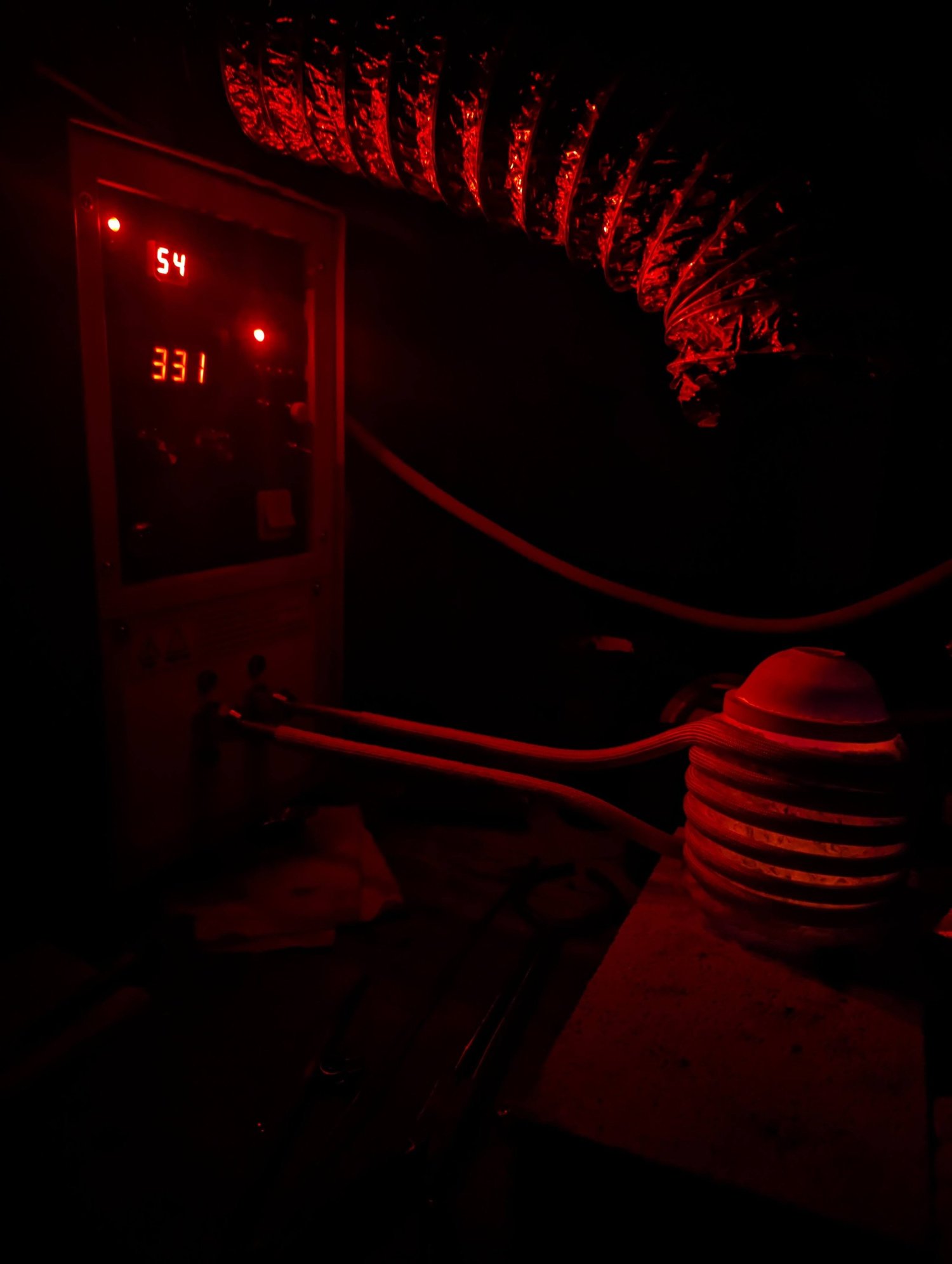
Personal project
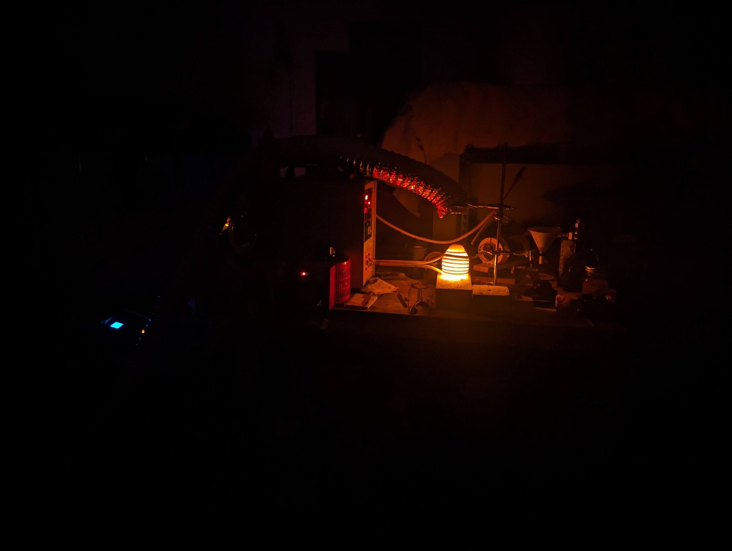
Quartz-tube induction furnaceA smaller crucible with a coverA similar induction-heating trial with a smaller graphite crucible. I placed a second crucible upside down over it as a cover, hoping to reduce heat lost through moving air. The stacked shape reminded me of a little beehive.
Personal project
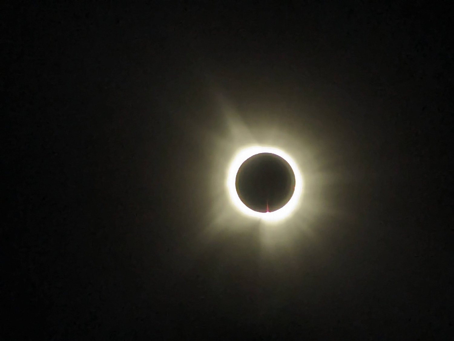
Quartz-tube induction furnaceAnother view of the covered crucibleAnother view of the small covered-crucible experiment. The upper crucible acted as a lid while I explored ways to retain more heat around the sample during induction heating.
Personal project
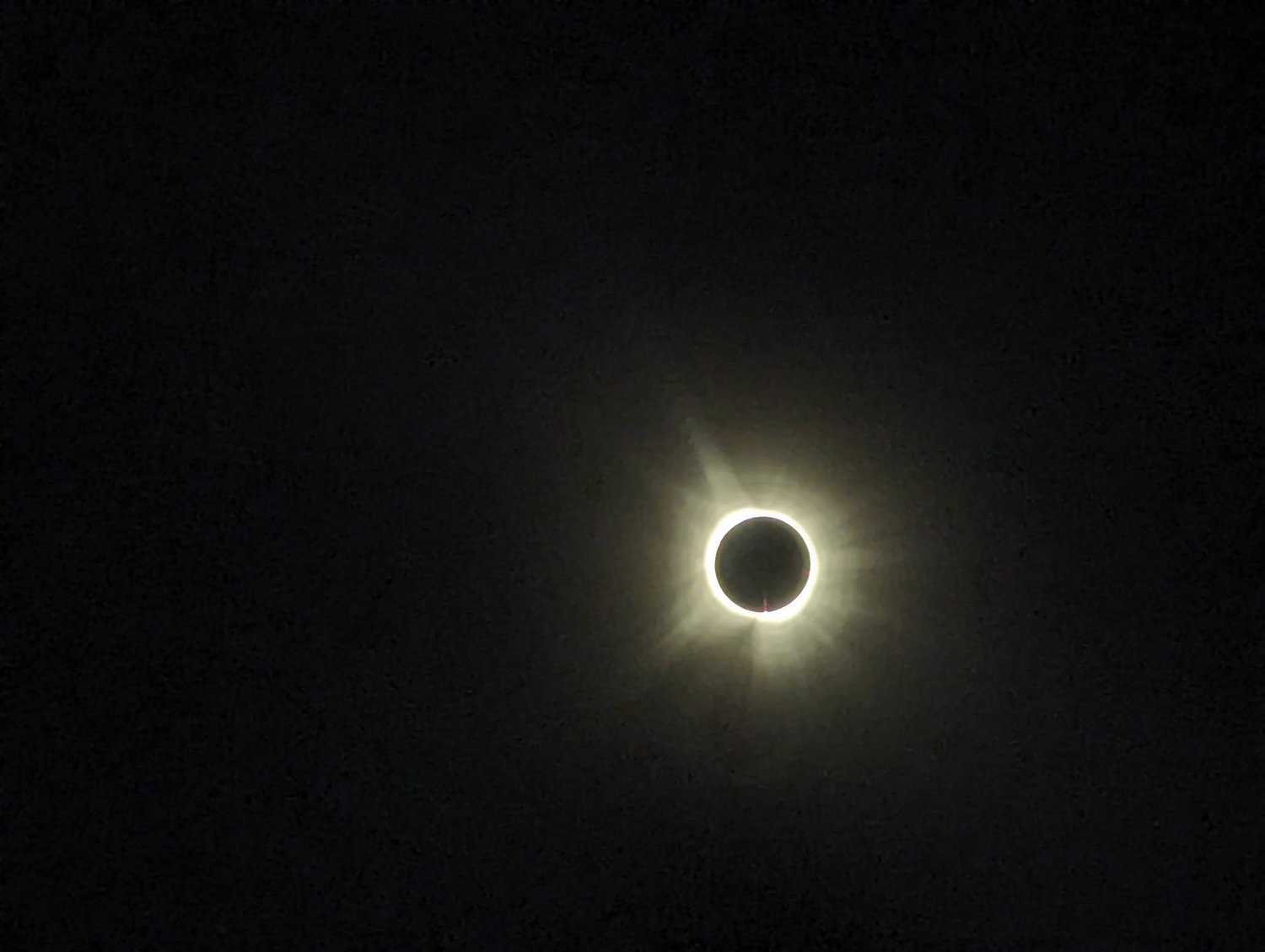
2024 solar eclipseSeeing the 2024 total solar eclipseA photograph from my trip to see the total solar eclipse in 2024. I drove a long way to reach the viewing area, and the experience was unlike anything I had seen before. I would gladly make another trip to see one again.
Personal project
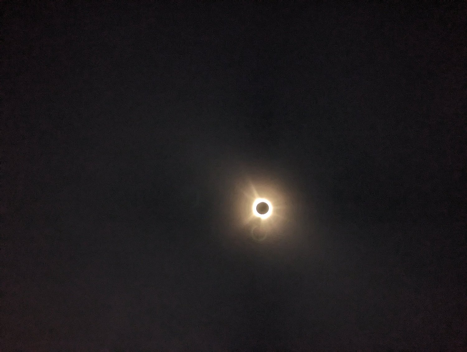
2024 solar eclipseAnother image from the eclipse tripAnother photograph from the 2024 eclipse, kept as a personal record of the experience. These images sit alongside my project work as a reminder of an especially memorable day of observing the natural world.
Personal project
2024 solar eclipseA personal record of the eclipseA further image from the same eclipse trip. I kept this group of photographs as personal notes from an event that made the long drive worthwhile.
Personal project
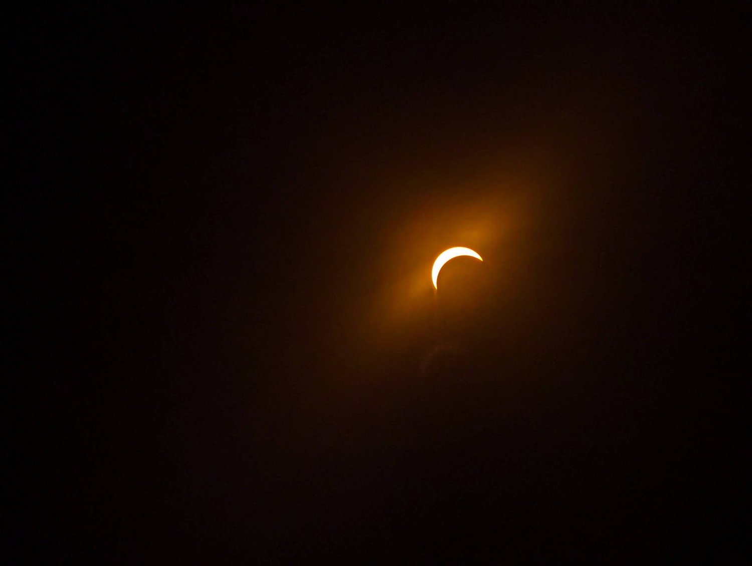
2024 solar eclipseThe Sun reduced to a crescentA partial phase of the 2024 eclipse, with the visible part of the Sun reduced to a bright crescent. This is one of the images I kept from the trip.
Personal project
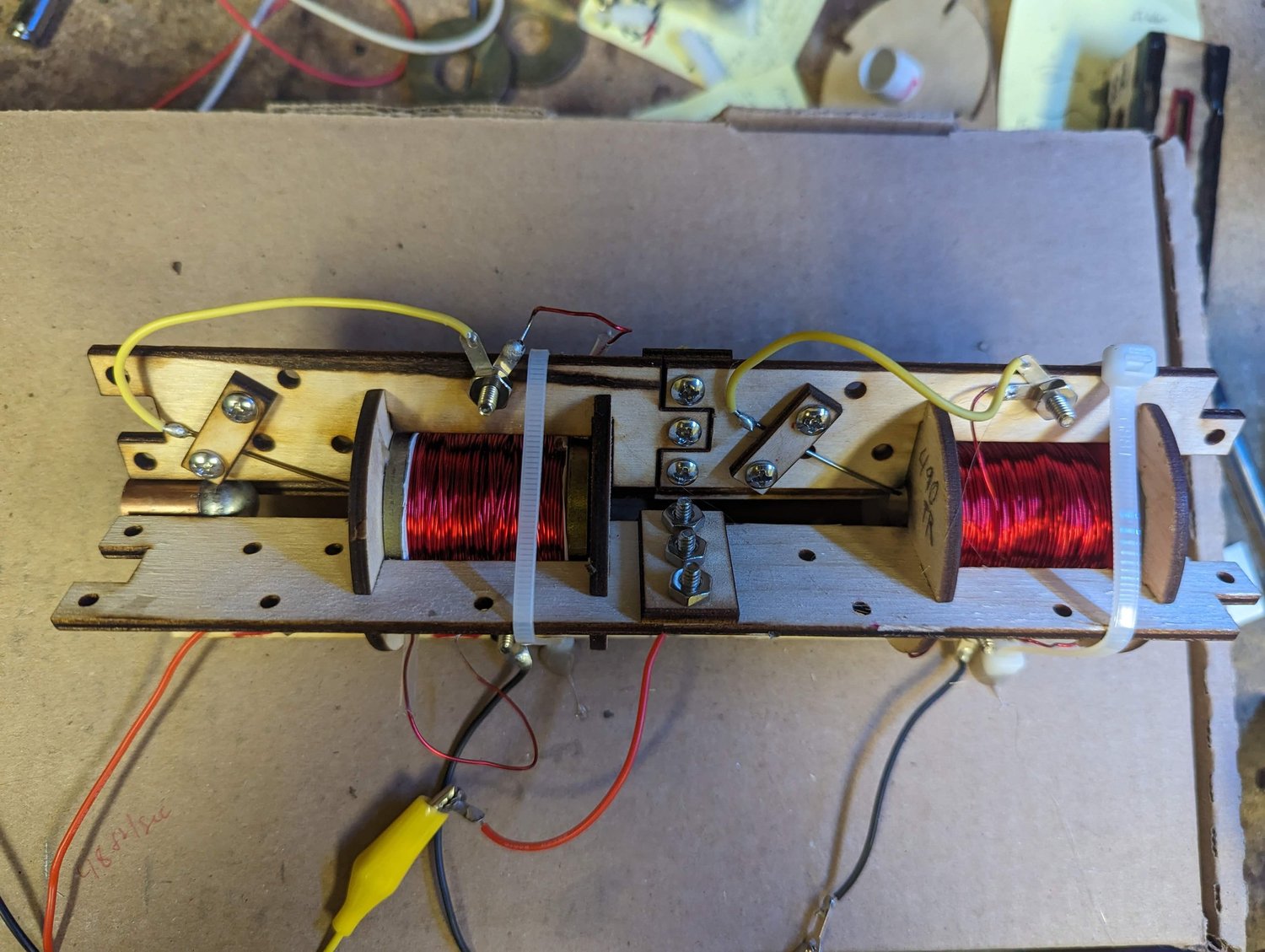
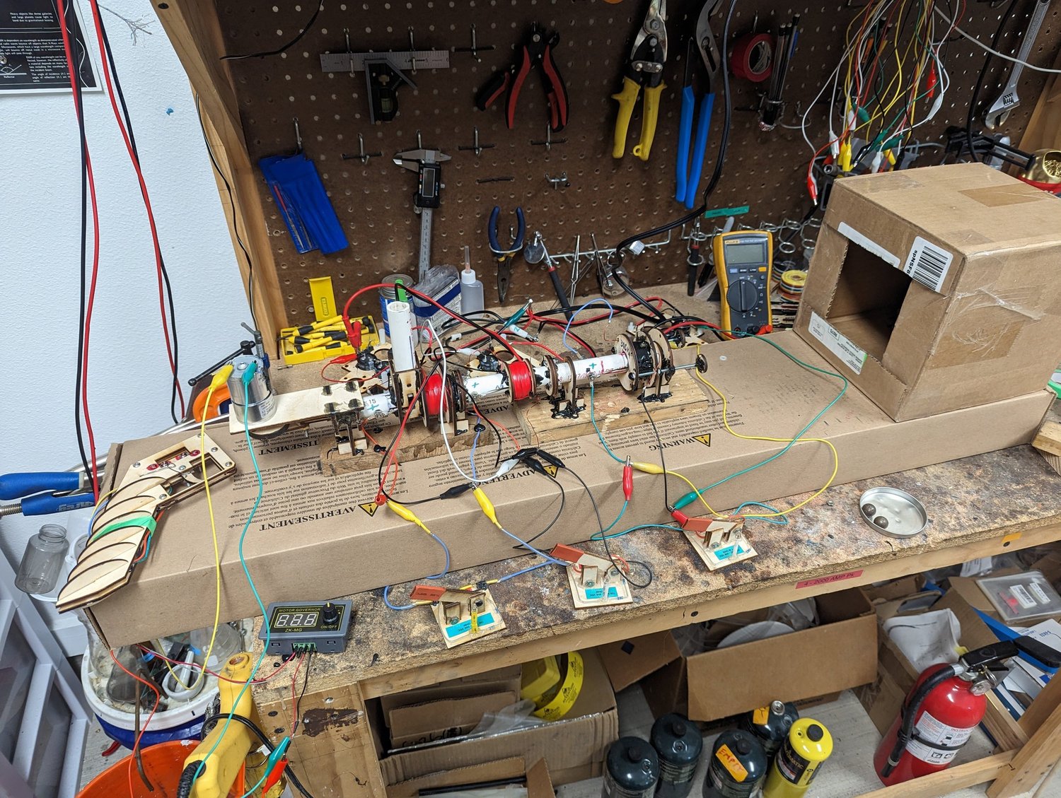
Magnetic-launcher experimentsAn electromagnetic launcher prototypeAn experimental electromagnetic launcher from an earlier electronics project. I used it to explore the relationship between electromagnetism, electrical switching, and motion, and documented several prototype variations during the work.
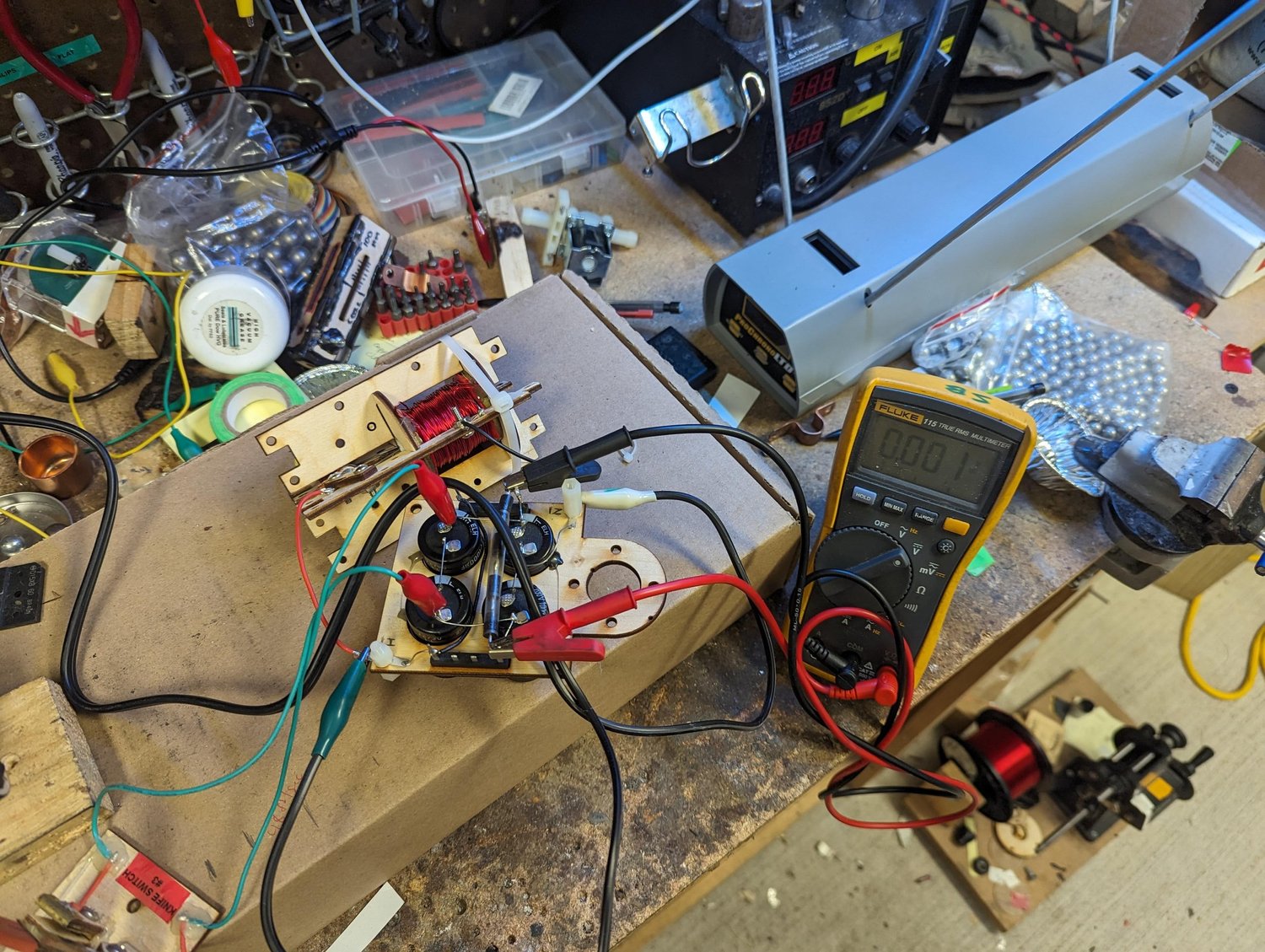
Personal project
Magnetic-launcher experimentsMeasuring the prototype’s motionA single-stage prototype beside a chronograph, an instrument used to measure the speed of a passing object. I no longer recall the measured result reliably, so this photograph records the test arrangement without assigning a speed.
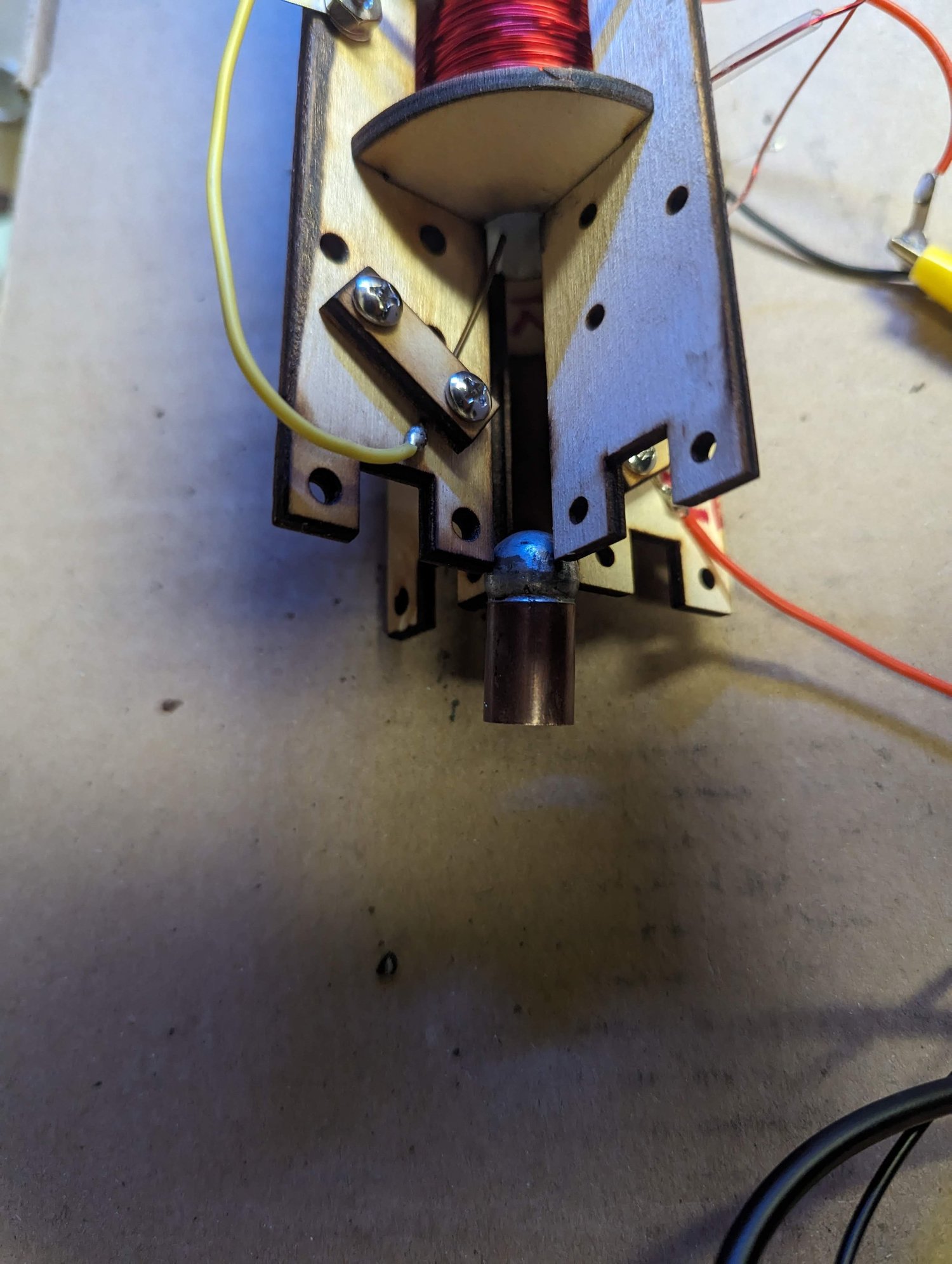
Personal project
Magnetic-launcher experimentsAnother view of the launcher prototypeA closer view of one end of the electromagnetic launcher prototype. This image documents the physical assembly from another angle as part of the project record.
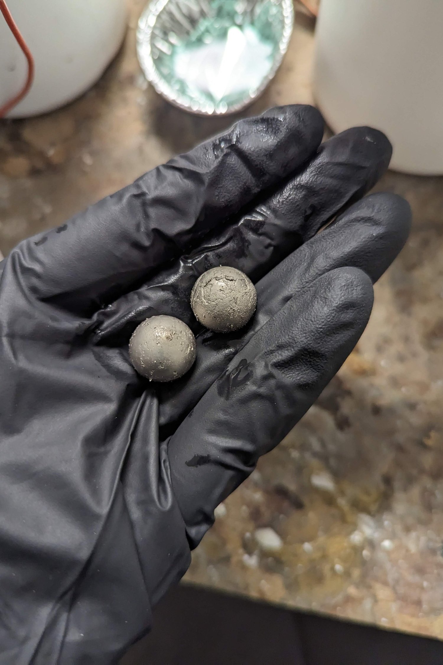
Personal project
Magnetic-launcher experimentsNickel and copper coating experimentsSurface-finishing experiments on iron ball bearings using nickel and copper coatings. This group of photographs records the plating work and the handling of the small metal samples during an earlier electronics project.
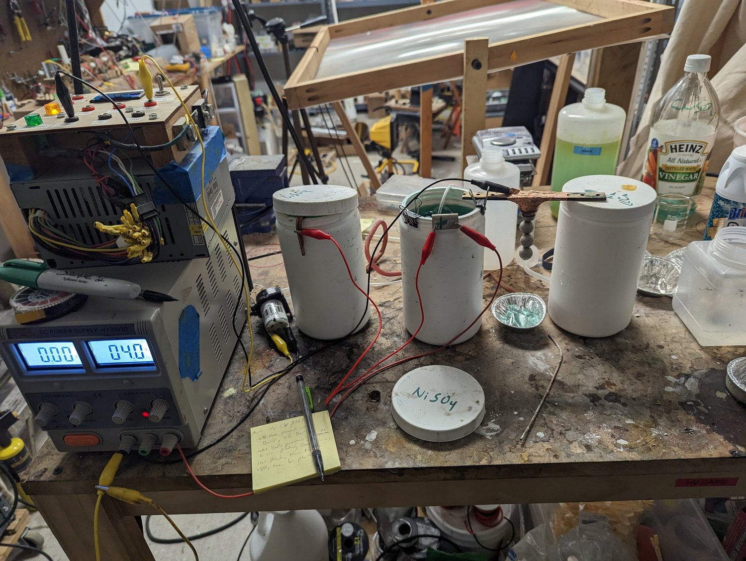
Personal project
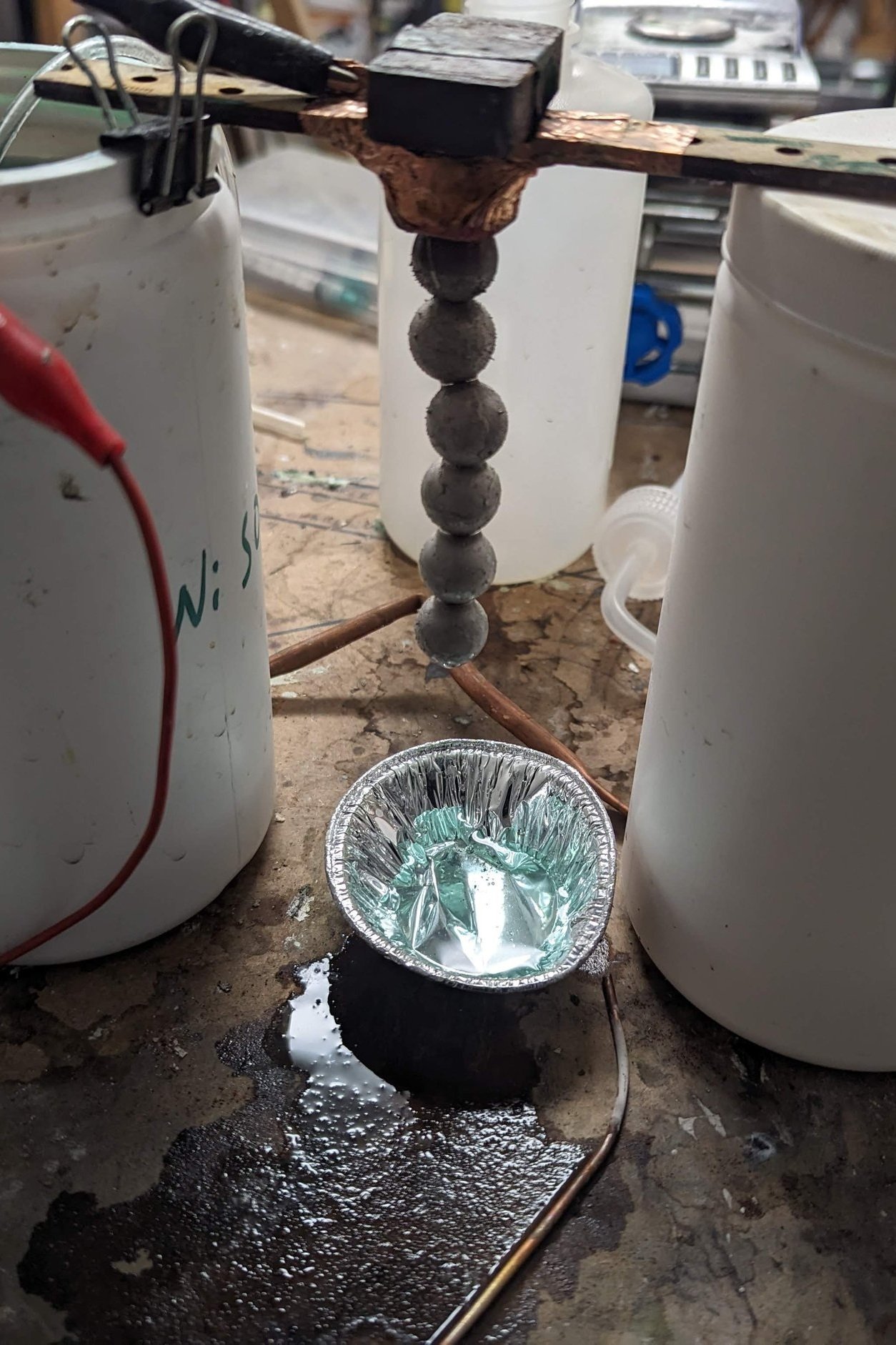
Magnetic-launcher experimentsThe electroplating benchThe bench setup for the coating trials, including a power supply, separate plating containers, and air-bubbling equipment. I used this arrangement while experimenting with metal finishes on the ball-bearing samples.
Personal project
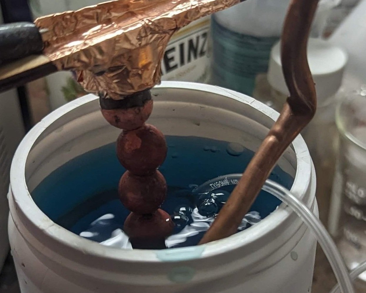
Magnetic-launcher experimentsRinsing the samplesThe ball-bearing samples being rinsed during the plating work. This photograph documents the handling and cleaning of the small parts between treatments.
Personal project
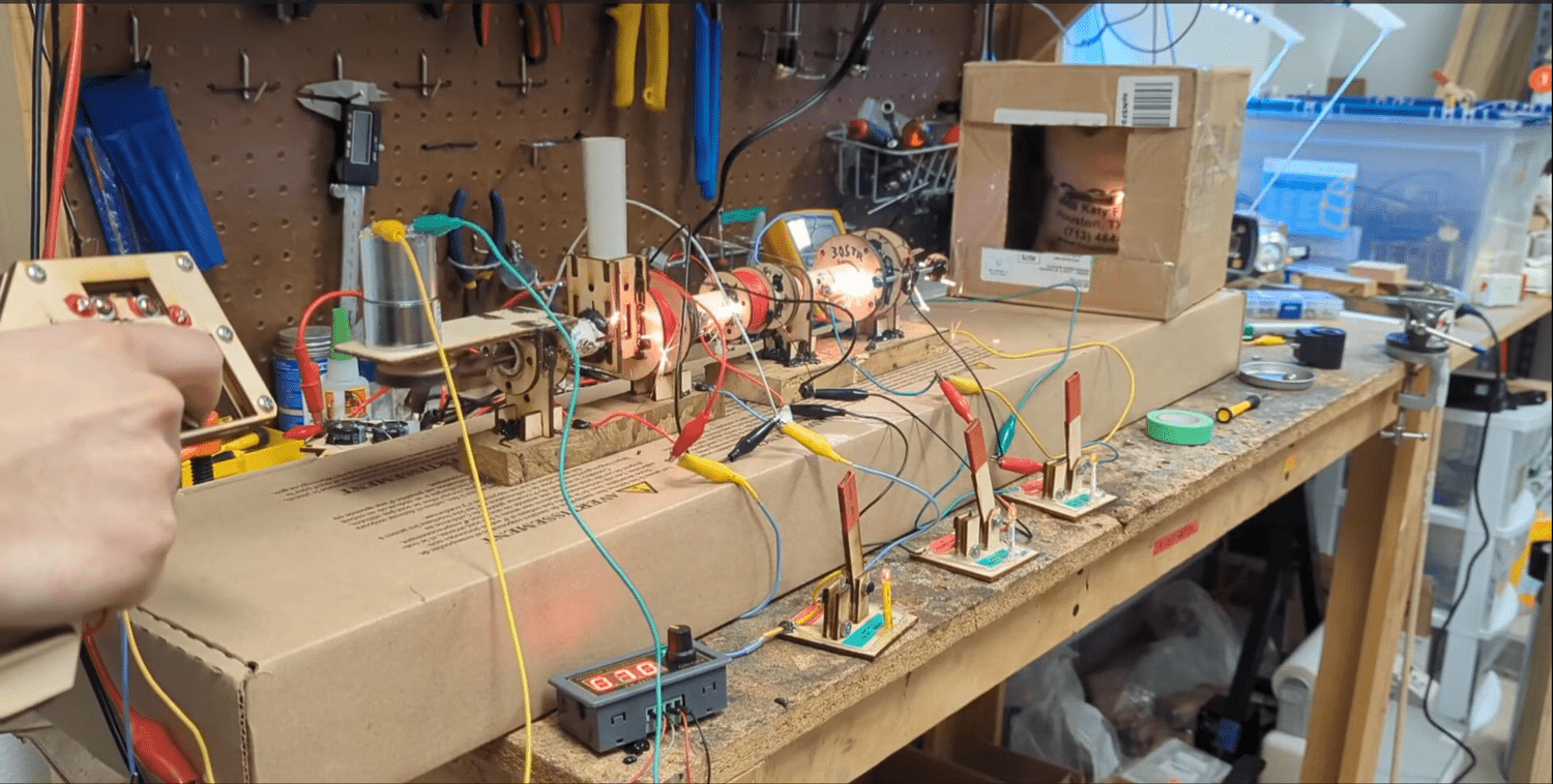
Magnetic-launcher experimentsA coating trial in progressThe metal samples immersed in one of the plating containers. This image is part of the record of my nickel and copper surface-finishing experiments.
Personal project
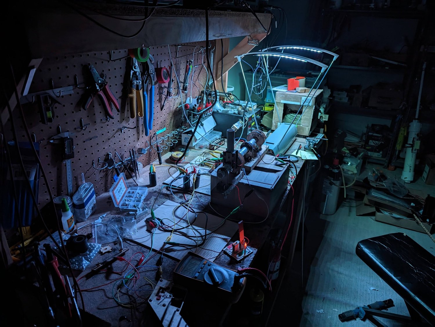
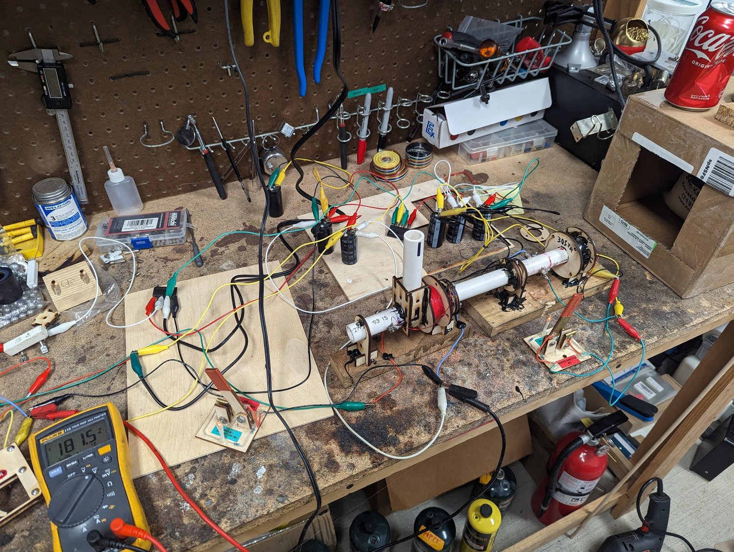
Magnetic-launcher experimentsAn earlier magnetic-launcher prototypeAn earlier experimental electromagnetic launcher, shown as a complete assembly. This project brought together electrical switching, mechanical components, and motion measurement, with several prototype versions documented along the way.
Personal project
Magnetic-launcher experimentsRecording speed measurementsA chronograph measurement setup used during the prototype tests. A chronograph measures the speed of an object as it passes through its sensing area. This photograph records the measurement equipment used with the experiment.
Personal project
Magnetic-launcher experimentsInspecting the prototype componentsA view from the troubleshooting work on the electromagnetic-launcher prototype. I documented the individual assemblies while investigating problems that came up during testing.
Personal project
Magnetic-launcher experimentsAnother view from the test benchAnother photograph from the same series of prototype inspections and tests. Together, these images record the experimental assembly and the work involved in evaluating it.
Personal project
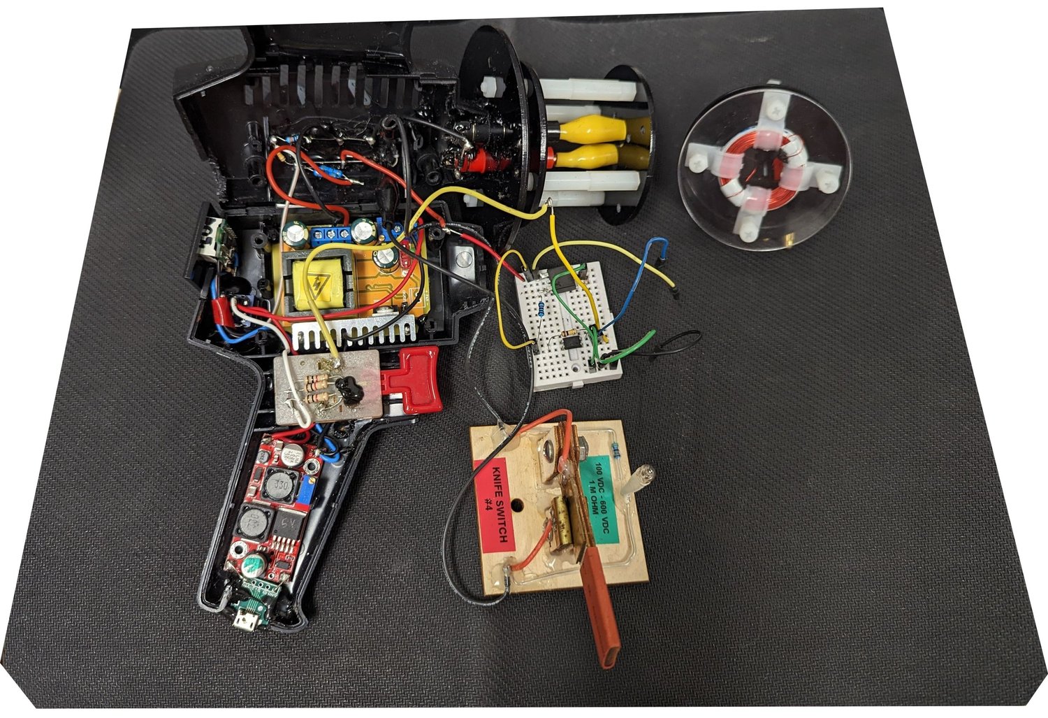
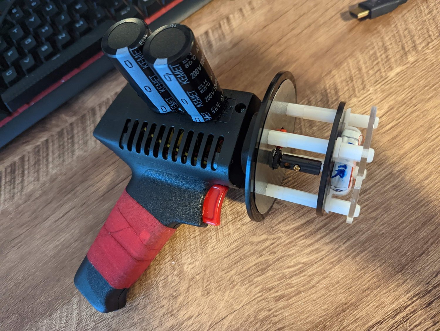
Handheld magnetic-pulse prototypeA handheld magnetic-pulse prototypeA one-off magnetic-pulse experiment built into an old welding-tool housing using salvaged components. The enclosure brought the prototype into a compact handheld form. A voltage display at the rear, outside this view, showed the stored-charge voltage.
Personal project
Handheld magnetic-pulse prototype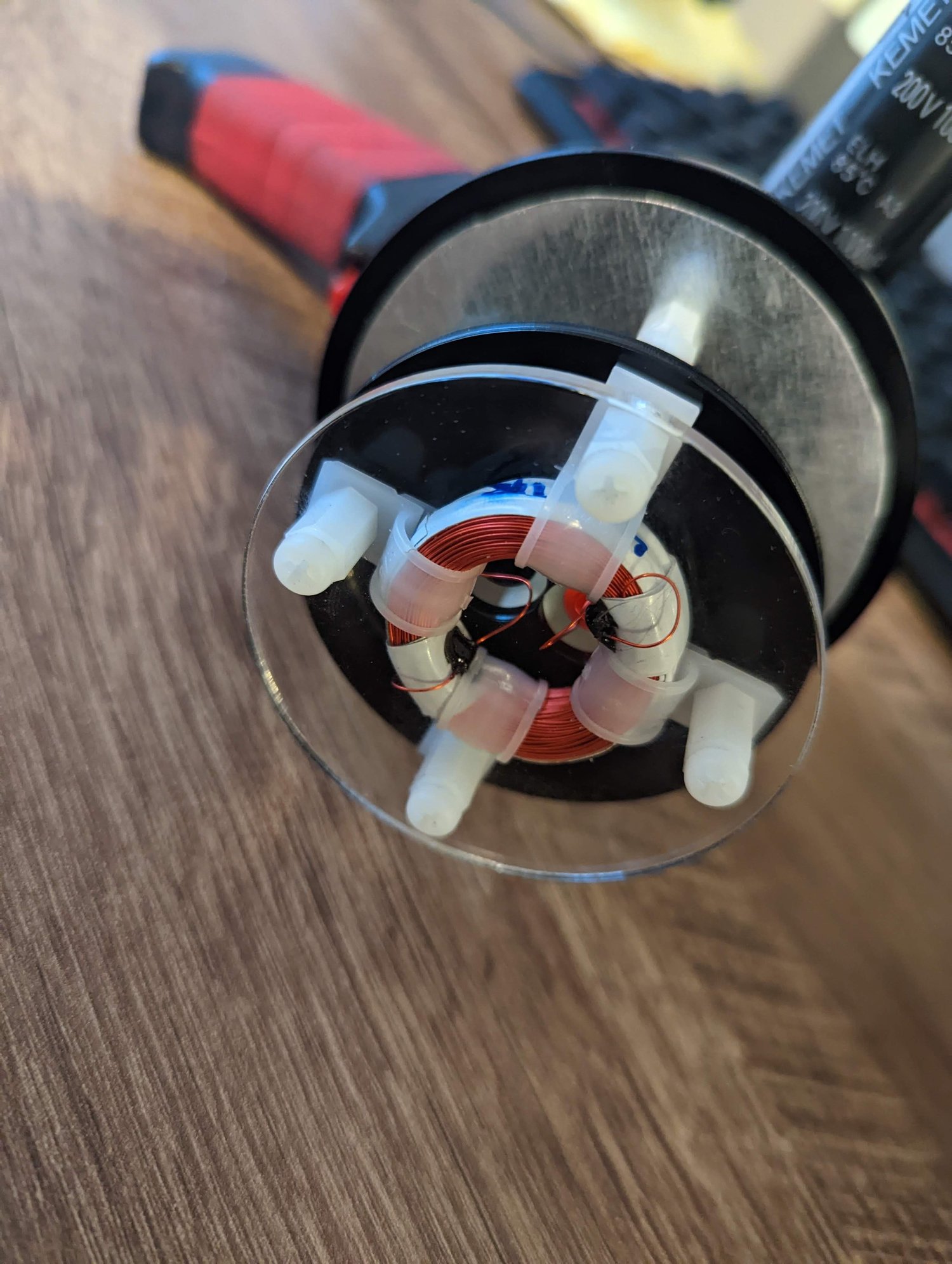
Personal project
Handheld magnetic-pulse prototype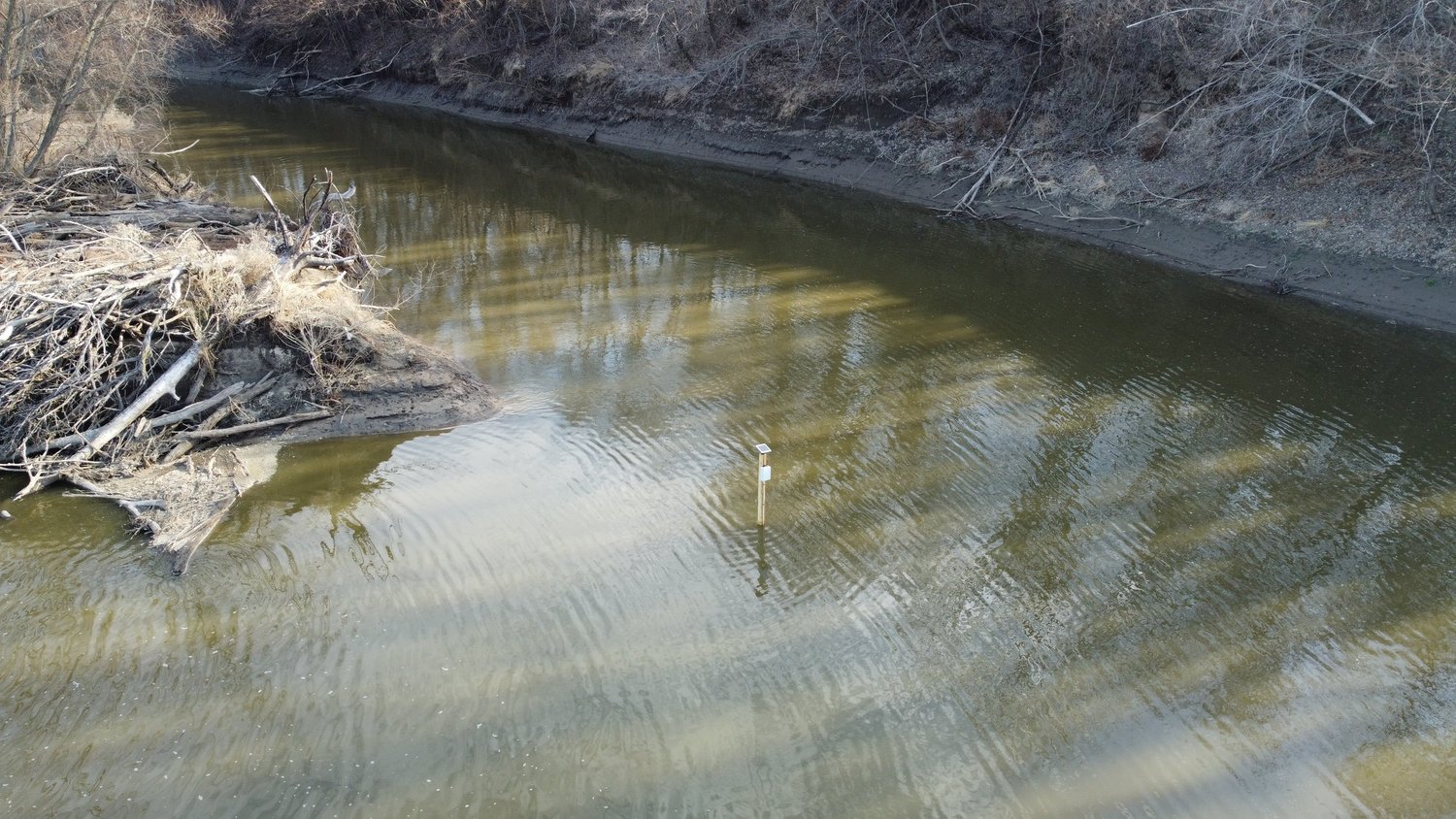
Personal project
Water-quality monitoringA river-deployed optical water monitorA water-monitoring prototype that I deployed on a river for roughly one to two months. It drew in water samples, measured transmitted light at different wavelengths, and compared the readings with a pure-water reference. A solar-charged battery powered the device. It stored readings locally, and I periodically visited with a handheld LoRa radio receiver to download the collected data for analysis.
Personal project
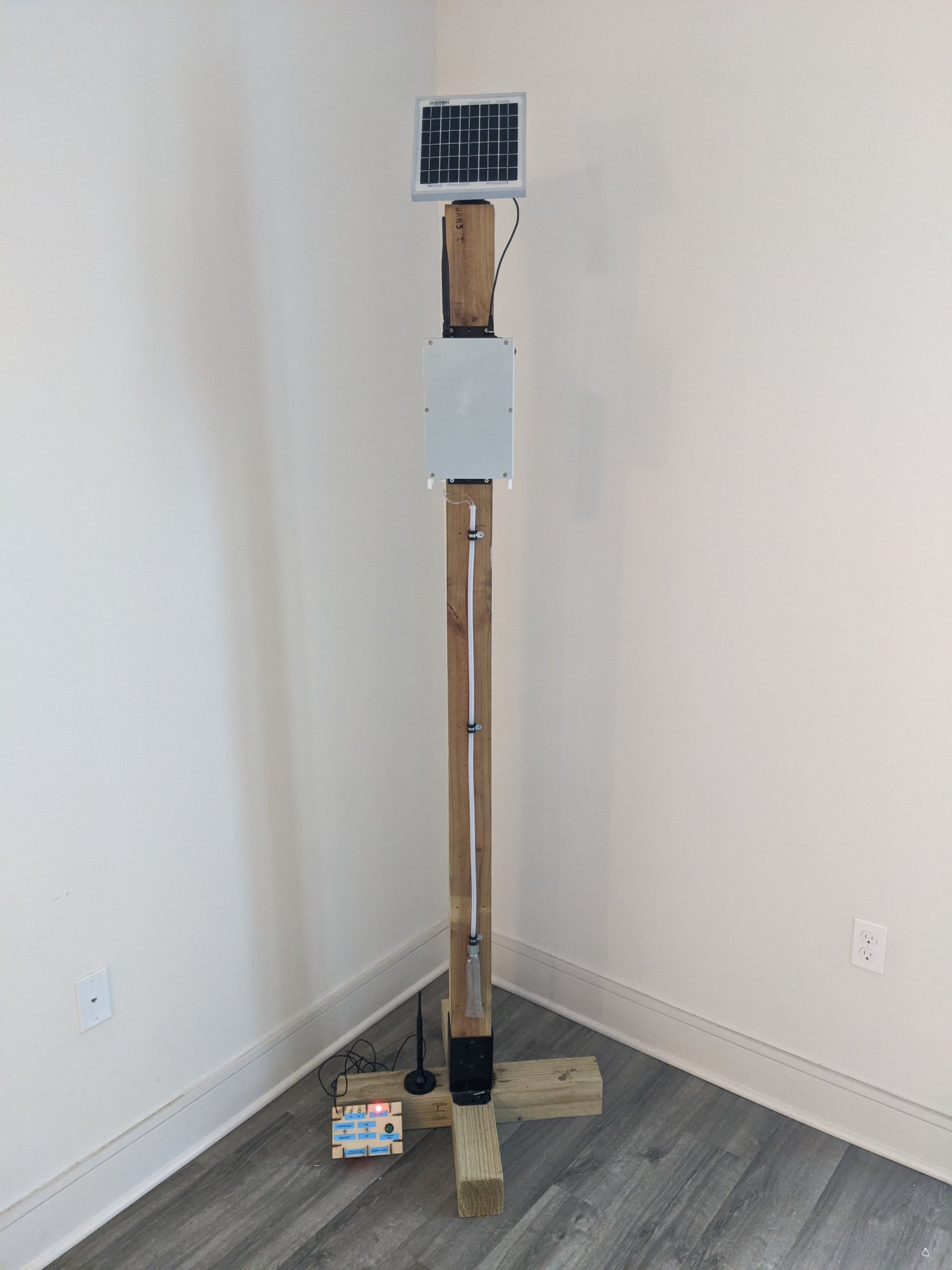
Water-quality monitoringThe monitor and its handheld receiverThe water monitor before deployment, with its handheld receiver below. The receiver’s antenna and controls let me request the stored measurements when I came within radio range, so I could collect data without opening the monitor’s enclosure.
Personal project
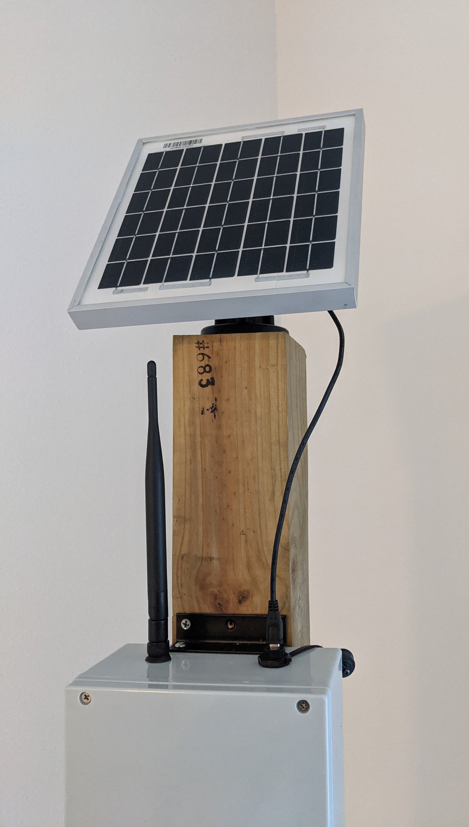
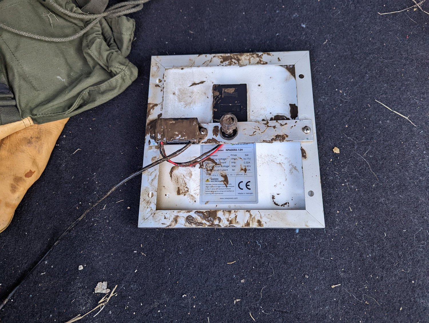
Water-quality monitoringAn updated solar panelA closer view of the solar-panel arrangement. I recall this version having a larger panel than the earlier prototype, intended to improve battery charging during extended deployment.
Personal project
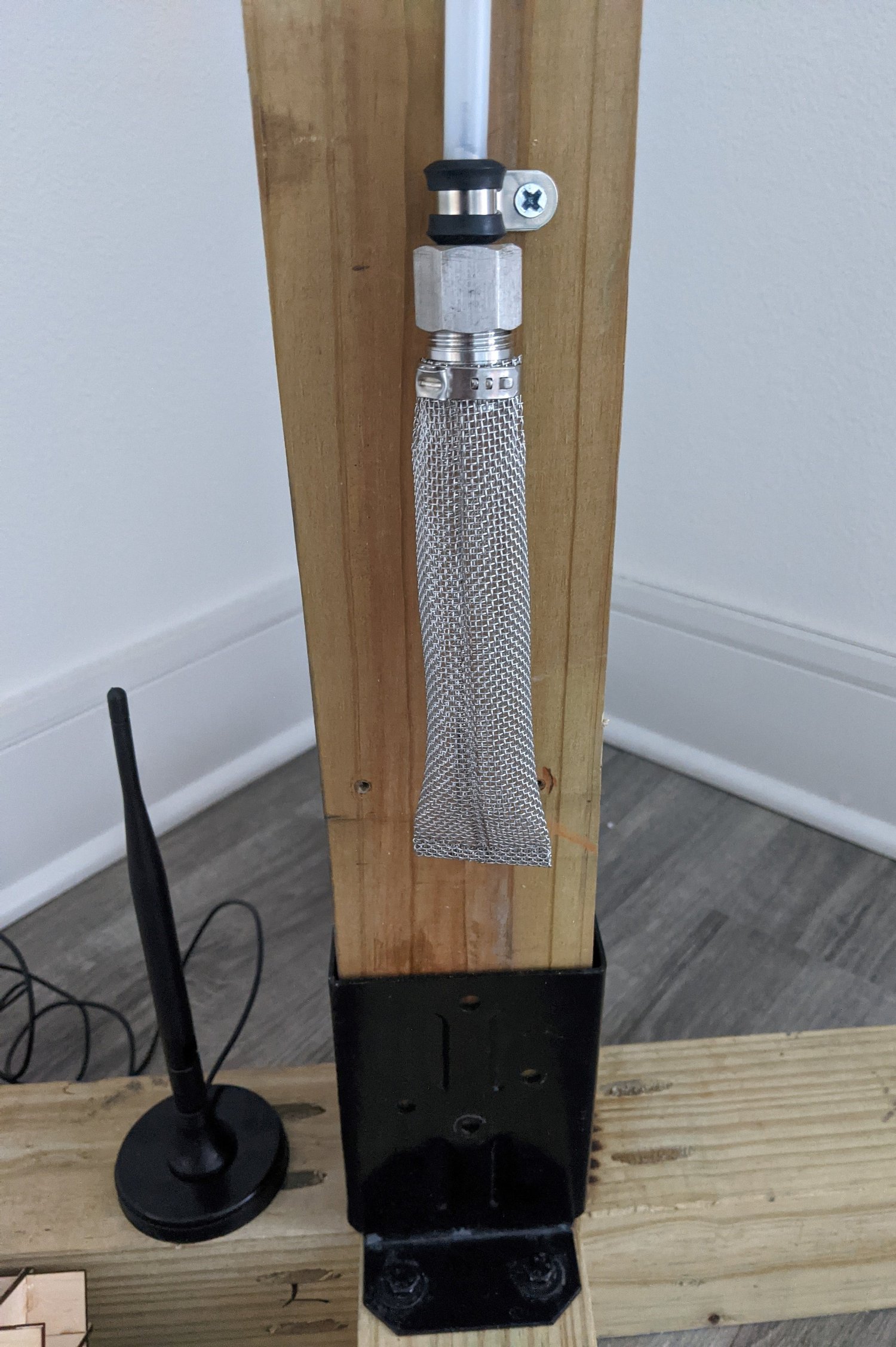
Water-quality monitoringKeeping debris out of the intakeA stainless steel mesh bag protected the water intake from debris. The pumped sampling system still depended on narrow tubing that could clog. For a future version, I would investigate placing the optical sensor head directly in the water and using a simple wiper to keep its window clean, removing the intake pump and tubing.
Personal project
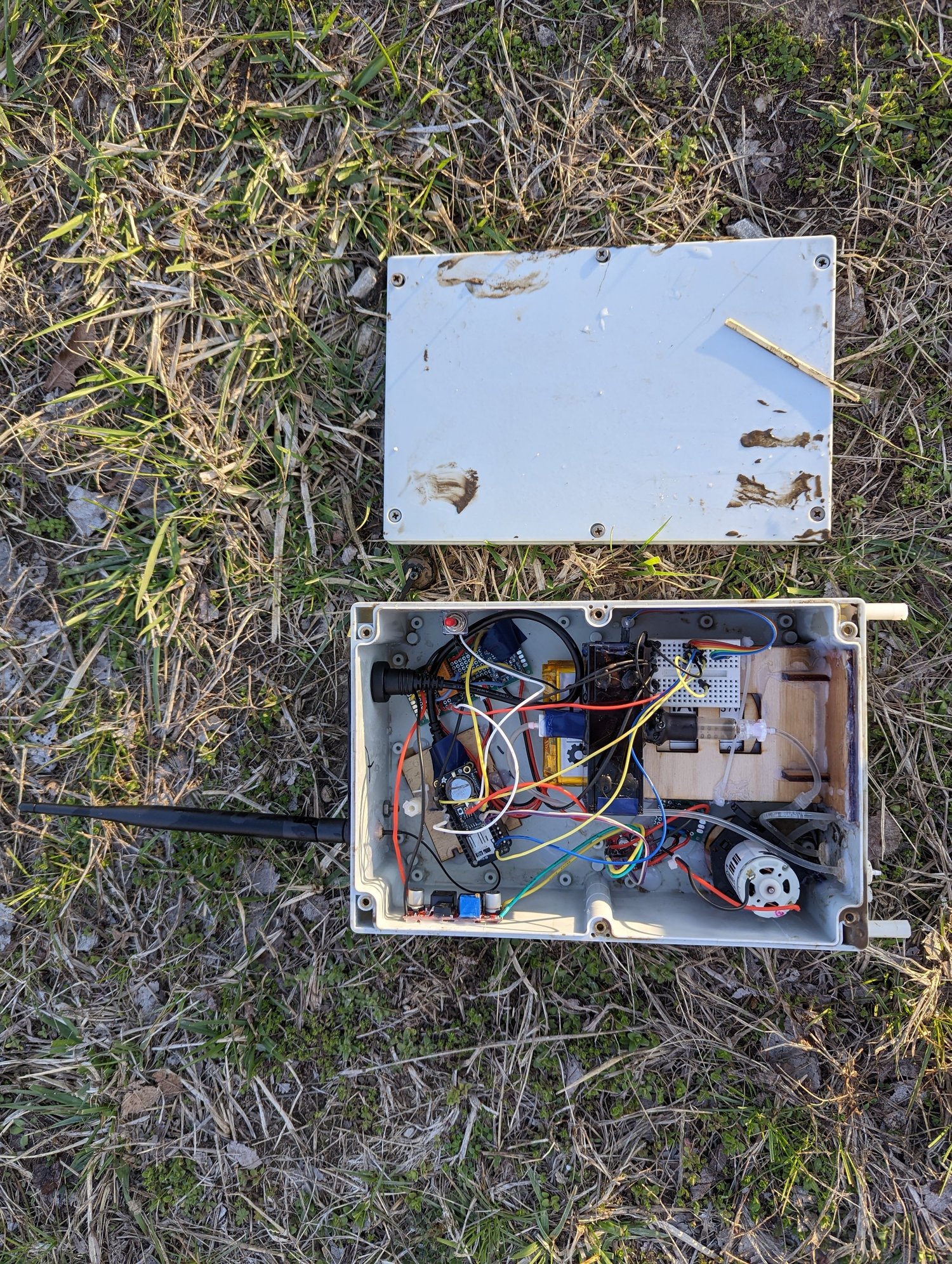
Water-quality monitoringFinding the monitor after high waterThe monitor after rising water had submerged the whole assembly for about a day or two. When the river receded, I was pleased to find it still attached; I had worried it might have been carried downstream.
Personal project
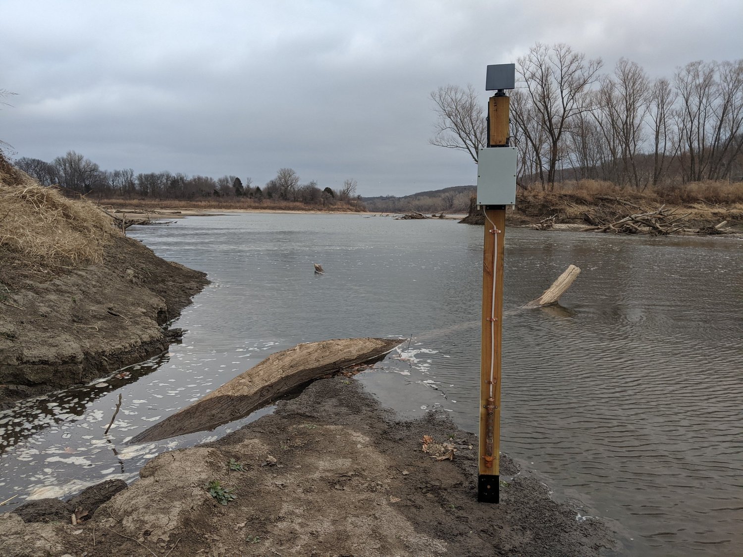
Water-quality monitoringBack in operation after rechargingAnother view after the submersion. The monitor appeared to have stopped because its battery ran down while the submerged solar panel could not recharge it. Once the battery was recharged, the device worked again.
Personal project
Water-quality monitoringAn earlier version with a copper intake guardAn earlier water-monitor prototype with a smaller solar panel and a copper-pipe guard around the intake. The guard helped keep larger debris away, but the narrow sampling tube remained a potential clogging point. This was one reason I later considered eliminating the pump and measuring directly in the water.
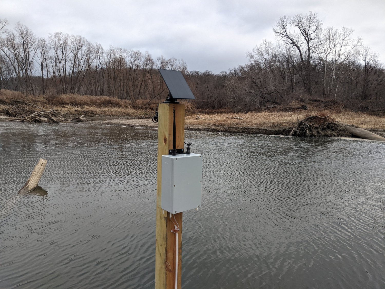
Personal project
Water-quality monitoringAnother view of the earlier river monitorA different angle on the earlier deployed monitor. This version combined solar power, radio data retrieval, and a pumped water-sampling arrangement in a compact assembly.
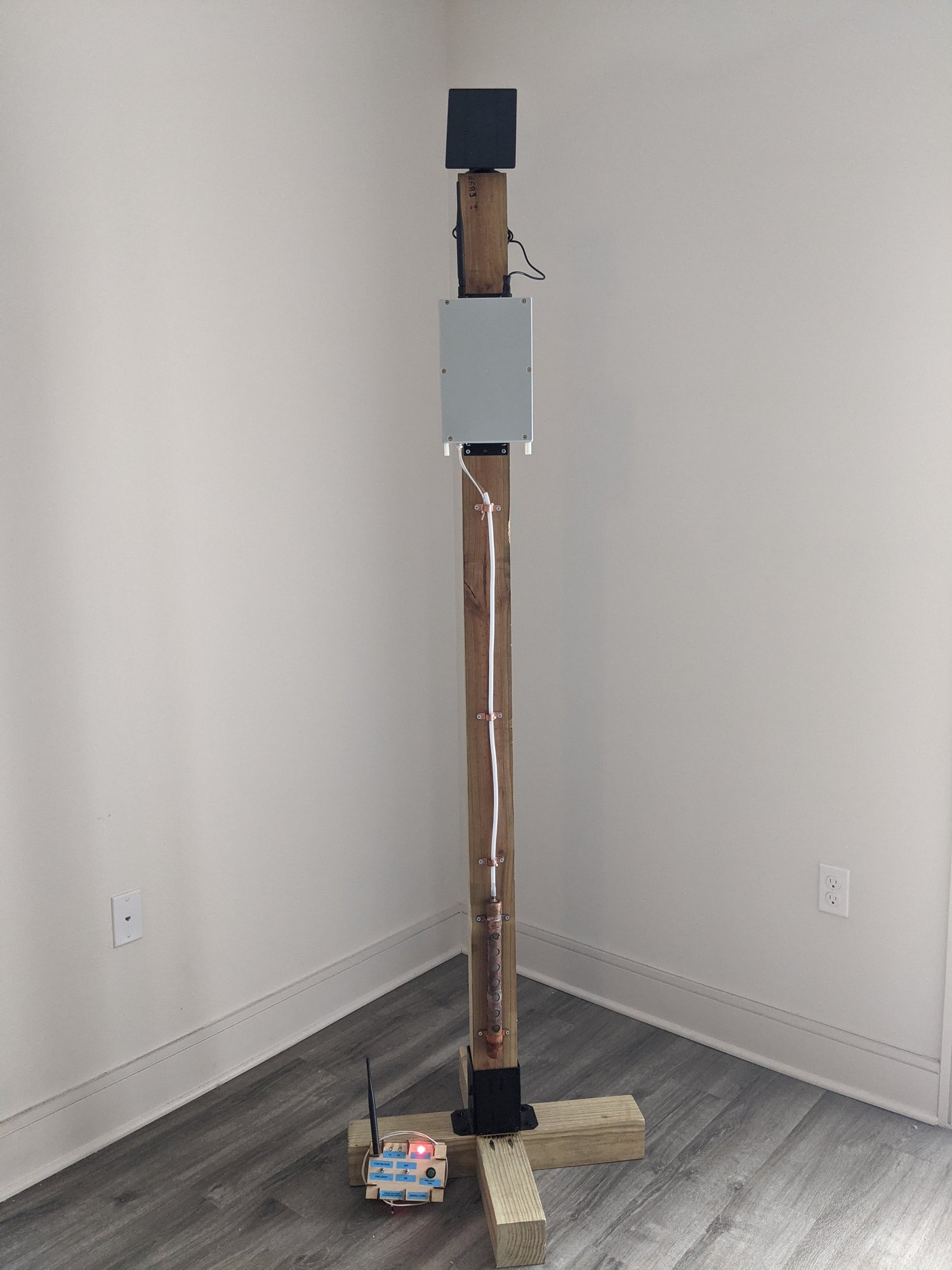
Personal project
Water-quality monitoringPreparing the earlier monitor for deploymentThe earlier water-monitor assembly before installation. This view records the prototype as it was prepared for testing beside the river.
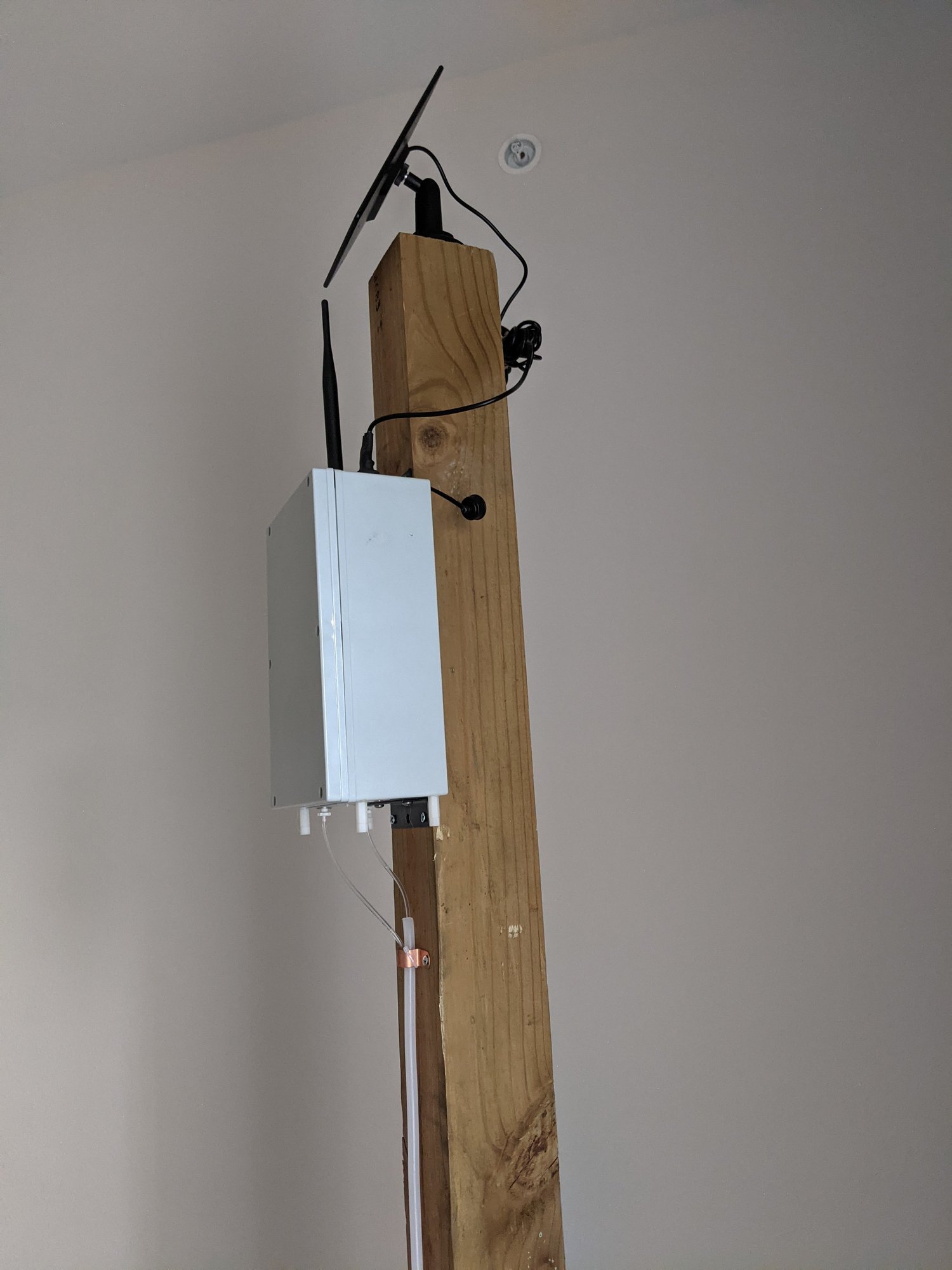
Personal project
Water-quality monitoringA second view before installationAnother view of the same monitor before deployment. These photographs document the assembly and its external components before the field test.
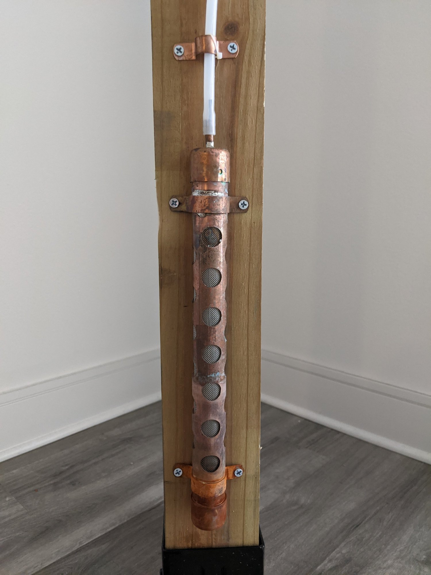
Personal project
Water-quality monitoringThe copper intake guardA closer view of the copper component used to guard the sampling intake. I was trying to reduce debris entering the device and also considered whether copper might help limit biological growth. The narrow tube behind the guard remained the more important reliability concern.
Personal project
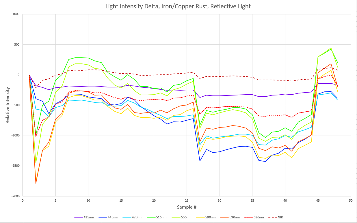
Water-quality monitoringComparing optical channels across samplesAn example of multichannel optical data: each colored trace represents a different wavelength band, and the horizontal axis follows successive samples. Plots like this let me compare how the measured light intensity changed across channels. This particular chart is labeled as a reflected-light test.
Personal project
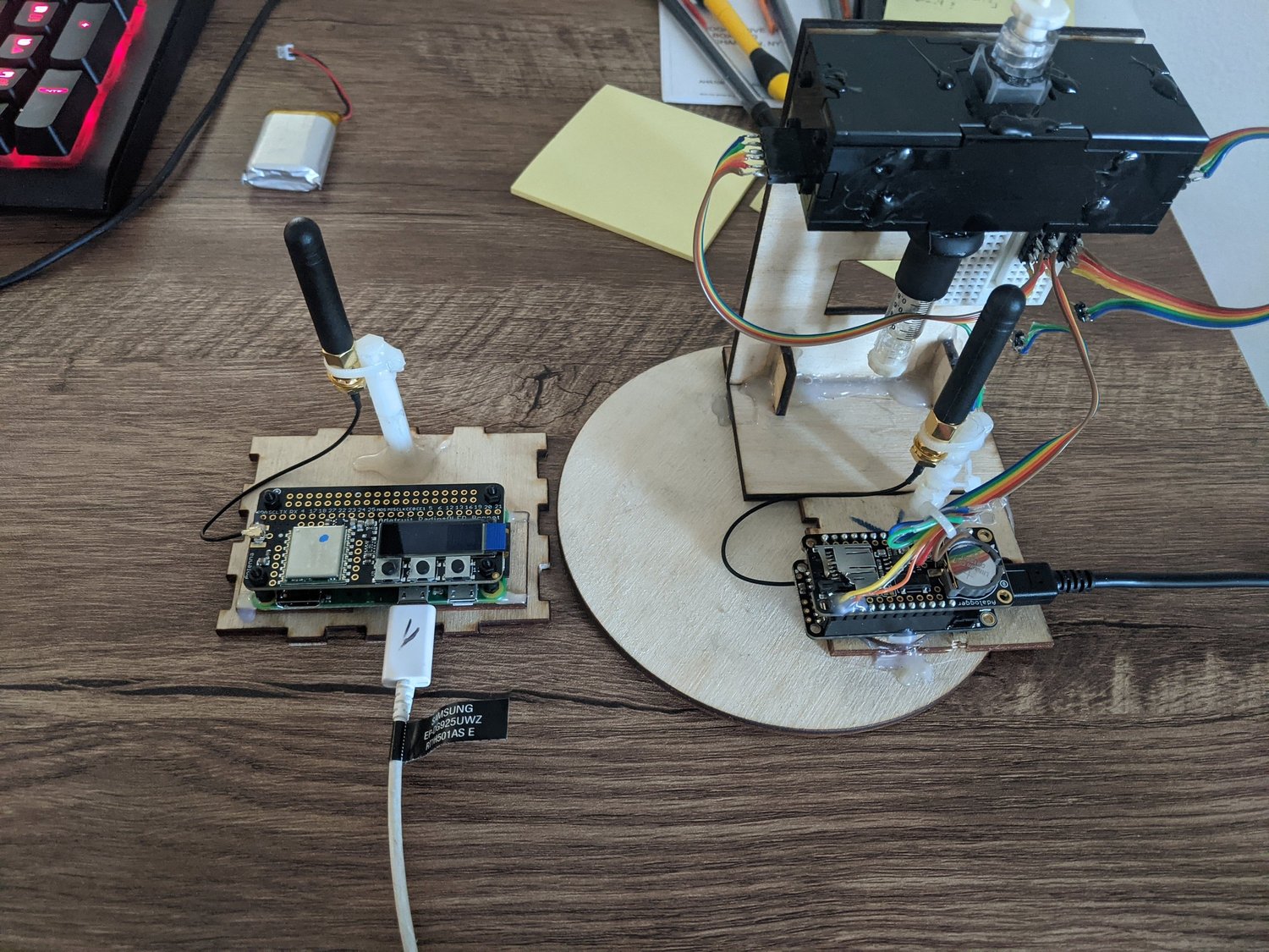
Water-quality monitoringAn early monitor-and-receiver pairAn early iteration of the optical water monitor and its radio receiver. I later changed the receiver and used larger antennas on both ends of the LoRa link while developing the field-deployment version.
Personal project
Water-quality monitoringA larger spectrometer-based water monitorAn earlier, larger monitor controlled by a Raspberry Pi. A tungsten lamp shone through the water sample; a lens and diffraction grating then spread the transmitted light across a linear photodiode array—a row of light detectors. I experimentally mapped detector positions to wavelengths and used their readings to compare the light transmitted by different samples.
Personal project
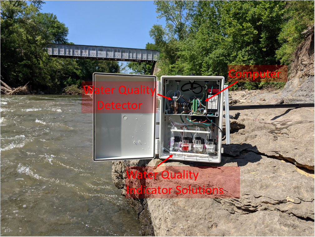
Water-quality monitoringThe optical sensor, computer, and reagent systemAn annotated view of the larger monitor’s optical sensor, computer, and indicator-solution containers. I explored adding wet-chemistry tests, but could not dose the reagents consistently enough, so I used the optical transmission measurements. For a future dosing system, I would investigate smaller peristaltic pumps, which move fluid by squeezing flexible tubing.
Personal project
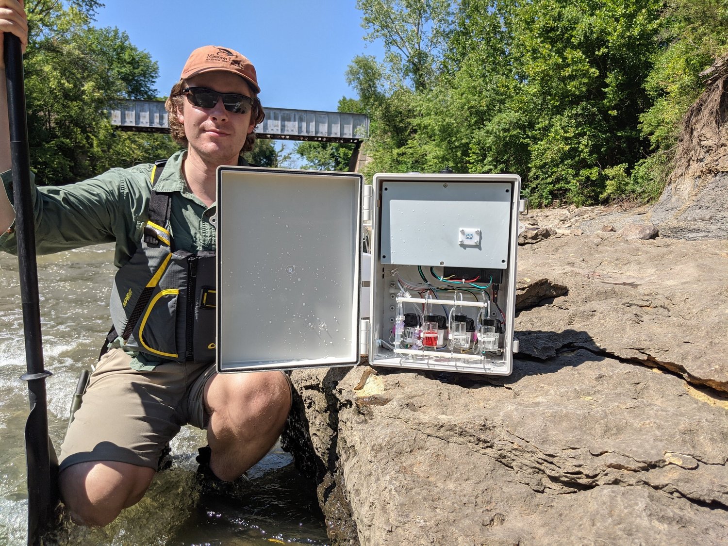
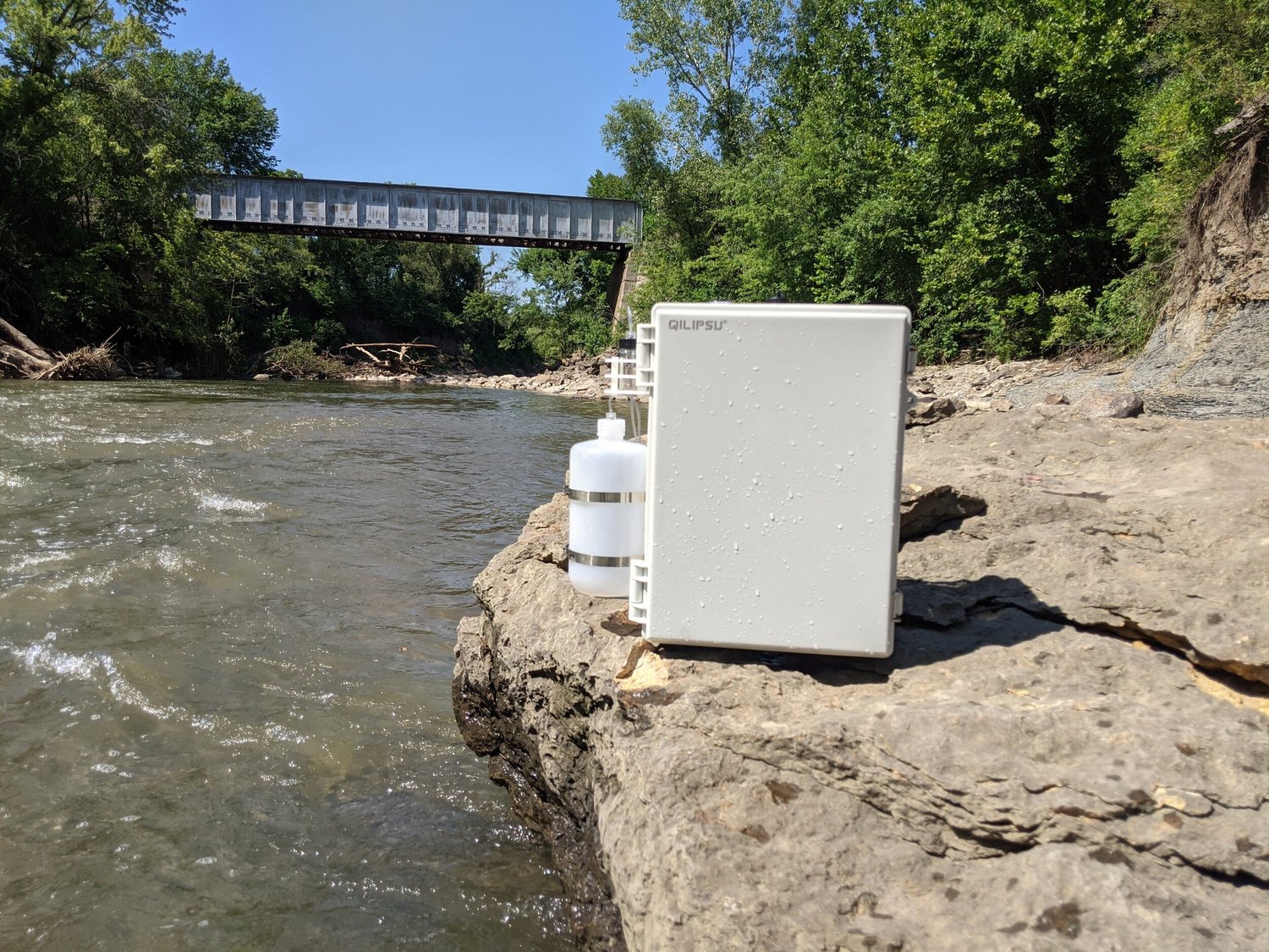
Water-quality monitoringThe enclosed monitor beside the riverThe larger water-monitor assembly with its enclosure closed, photographed at the river. Later iterations enclosed the sample’s fluid path more fully to reduce the risk of overflow if a pump failed to stop.
Personal project
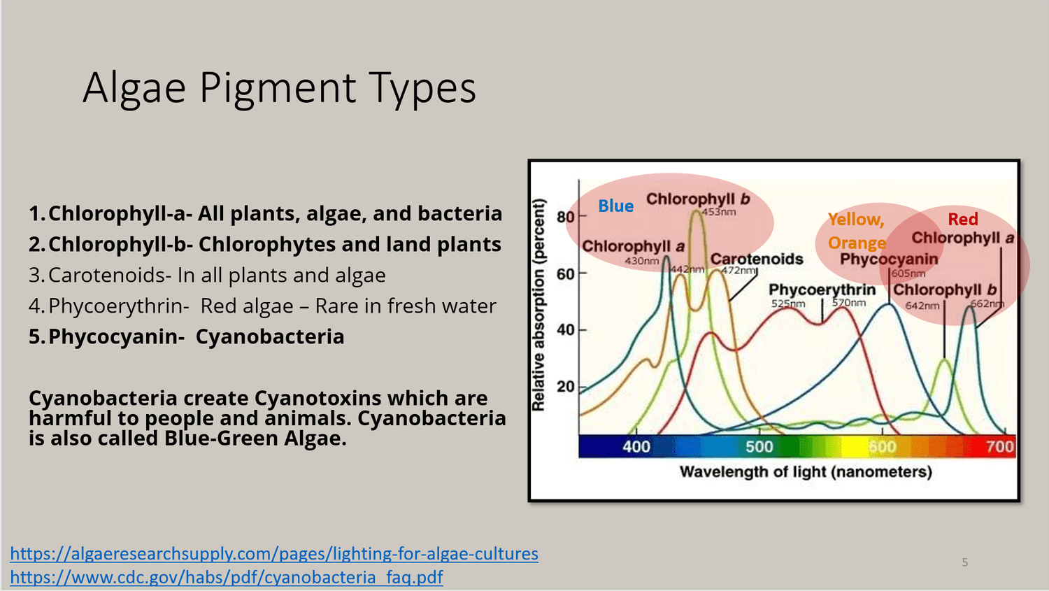
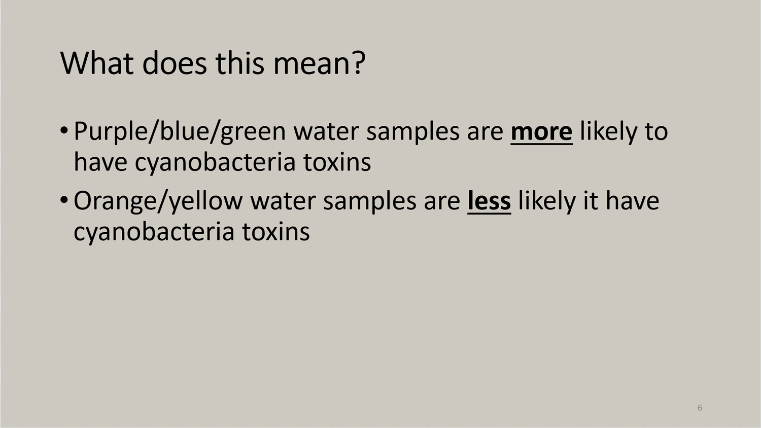
Water-quality monitoringA hypothesis that still needed calibrationI was investigating whether reduced light transmission at particular wavelengths could suggest the presence of different algae pigments. The next step was to grow known algae cultures and compare their measurements, but a move interrupted the project before I did that work. I still have the device; calibration and controlled validation remain necessary to turn the idea into a reliable monitoring product.
Personal project
Water-quality monitoringExplaining the idea to water-quality specialistsOne of the slides I shared with my local water authority and water-quality scientists. I wanted to explain the optical approach, why differences between algae pigments interested me, and what I hoped further experiments could establish.
Personal project
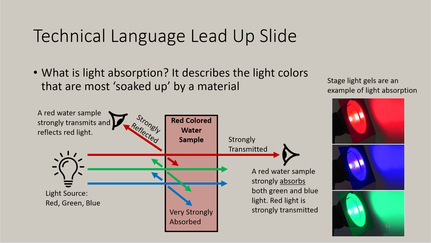
Water-quality monitoringExplaining how light interacts with a sampleA slide for a less technical audience, introducing light transmission, absorption, and reflection. It helped explain the measurement idea: shine light through a water sample and compare the light that emerges with a reference measurement.
Personal project
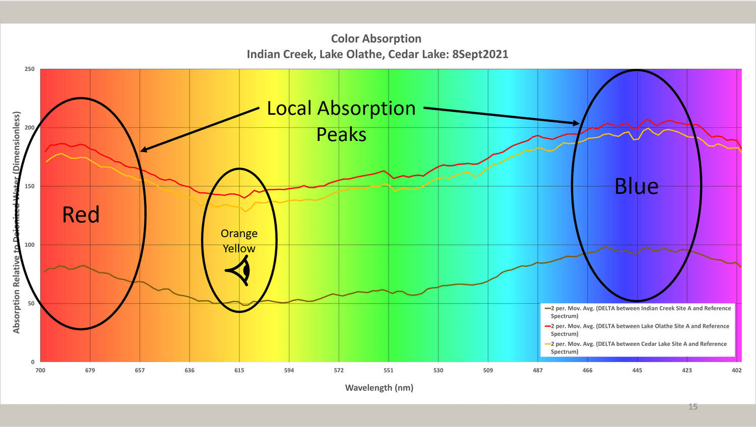
Water-quality monitoringReading the shape of a sample’s optical responseAn example of the wavelength-by-wavelength plot produced from water samples. I interpreted the highlighted peaks as stronger losses of red and blue light, with weaker losses in the orange-yellow region. That pattern suggested an orange-yellow appearance for the sample. The graph compares the optical response with a reference; it was part of an exploratory study.
Personal project
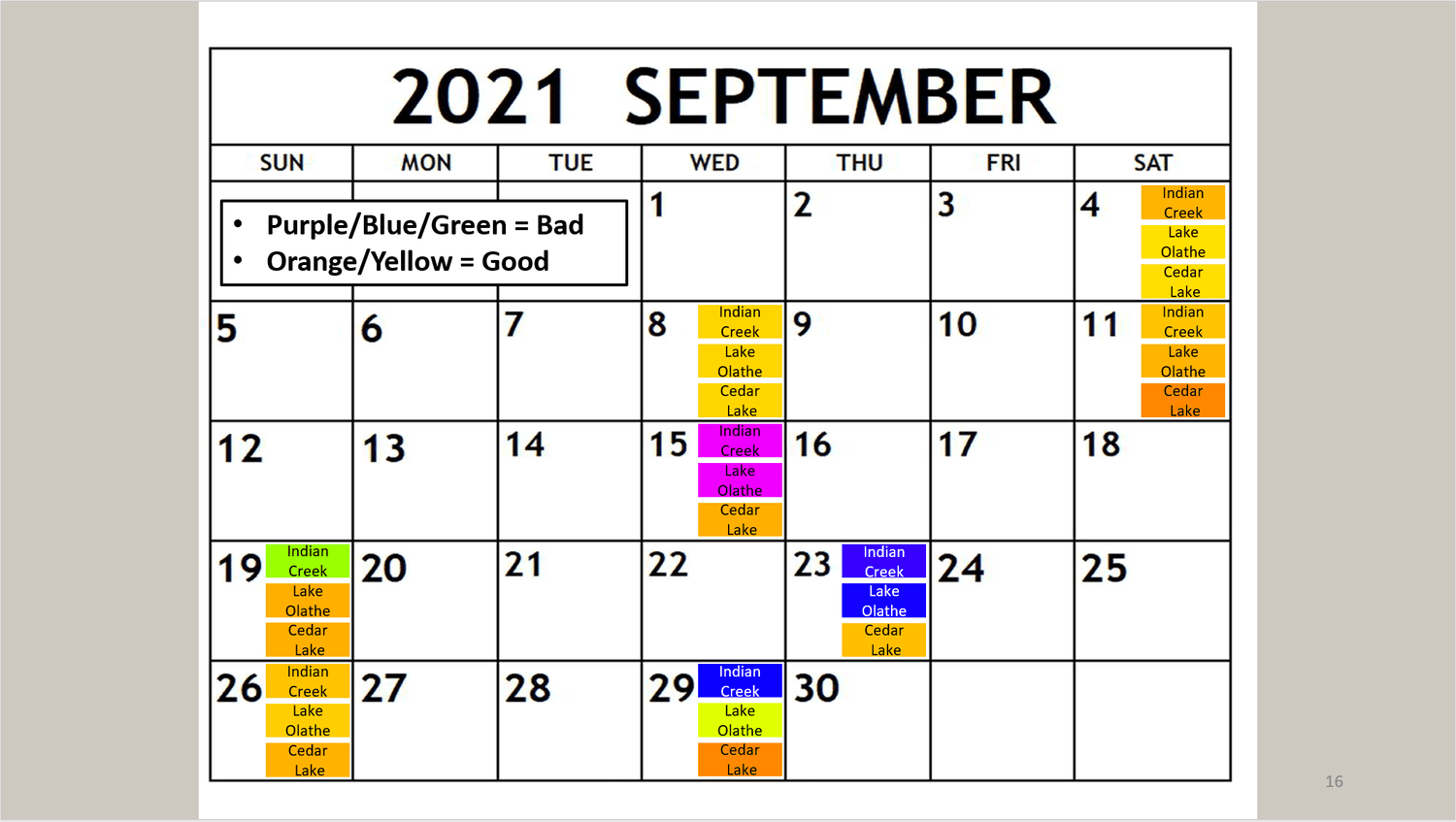
Water-quality monitoringA month of sampling at three locationsA sampling calendar from a monthlong study at three locations. I collected water in jars from the same places, brought the samples home, and ran them through the instrument. The calendar records changes in the optical patterns over time. Its ‘good’ and ‘bad’ labels reflect my early, unvalidated interpretation of those patterns.
Personal project
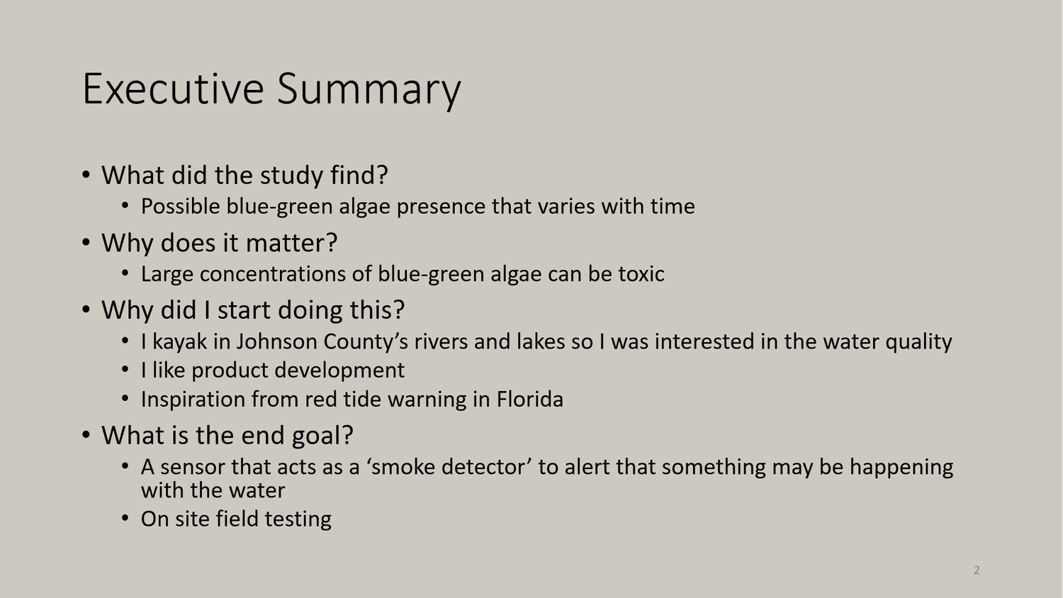
Water-quality monitoringEarly observations and an open questionA summary of the exploratory study. I noticed a tendency toward blue-purple patterns on weekdays and orange-yellow patterns on weekends, and wondered whether activity during the working week might be related. A connection to pollution was a hypothesis that needed checking; the study did not establish a cause or confirm particular algae in the samples.
Personal project
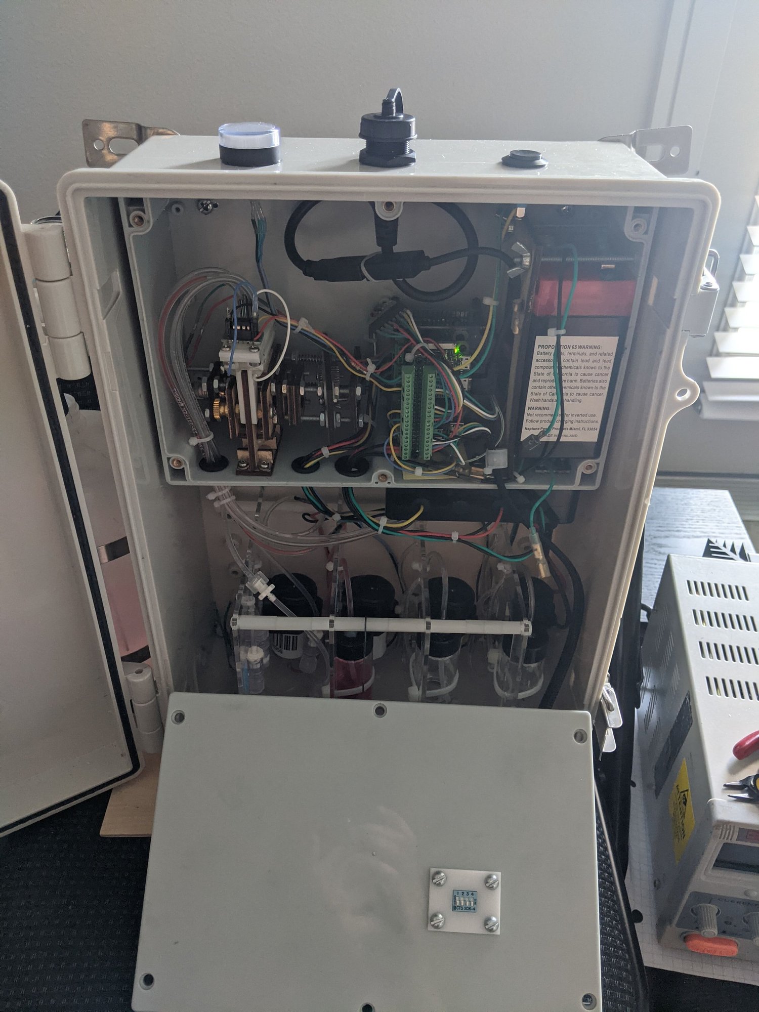
Water-quality monitoringInside the optical sensorThe sensor’s internal components, including the tungsten light source, water-sample slot, lens, diffraction grating, linear photodiode array, and battery. The optical components spread the transmitted light across a row of detectors so I could compare different parts of the spectrum.
Personal project
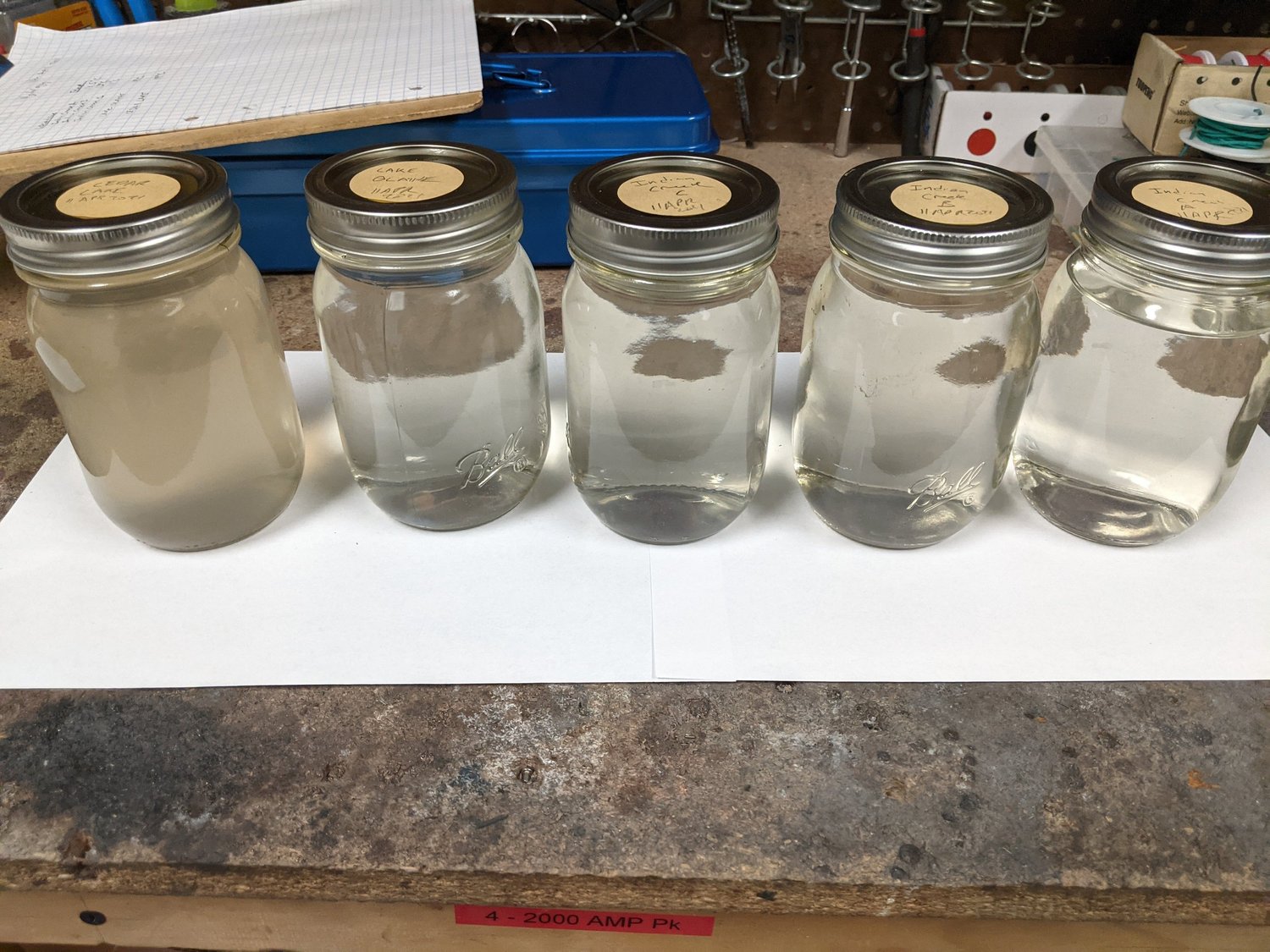
Water-quality monitoringWater samples collected for testingThe jars used to bring samples back from the three collection locations. I tested the collected water at home and compared the resulting plots to follow changes between sites and sampling days.
Personal project
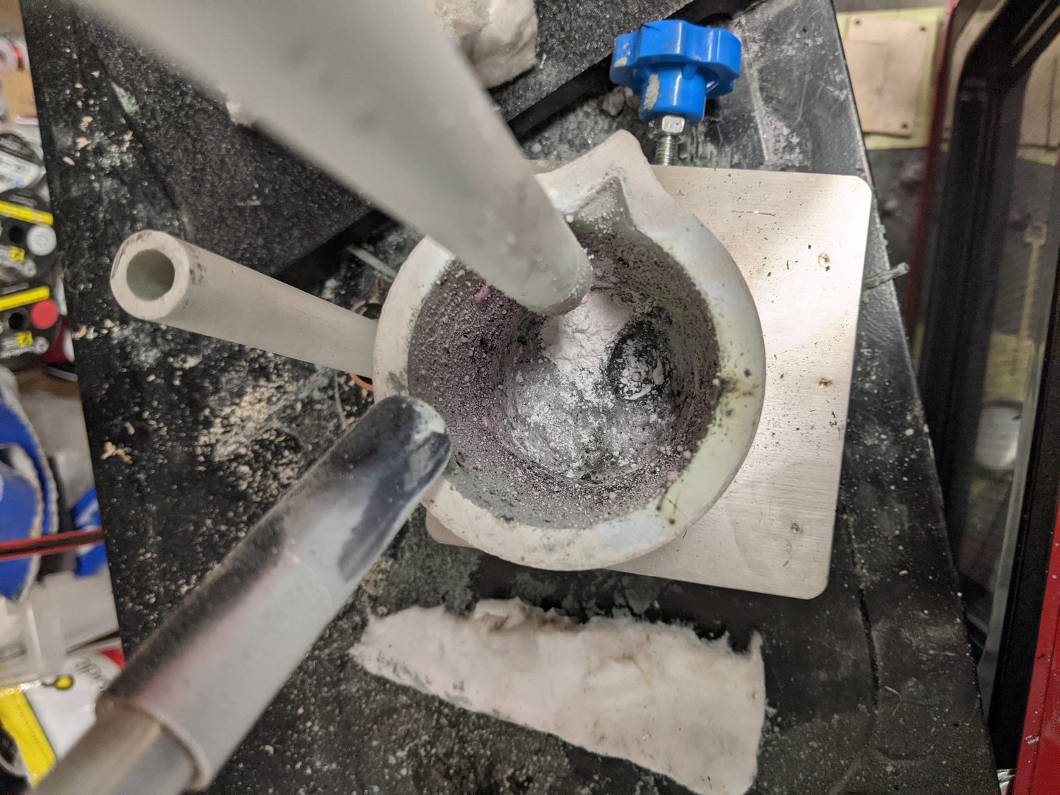
Chemical ruby experimentAn early combustion-based crystal experimentAn early attempt to produce corundum through a combustion-based process. The intense reaction left an oxide mass that I interpreted as sapphire or corundum, but it contained substantial impurities. I would not repeat this arrangement. It was an exploratory result rather than a controlled crystal-growth process.
Personal project
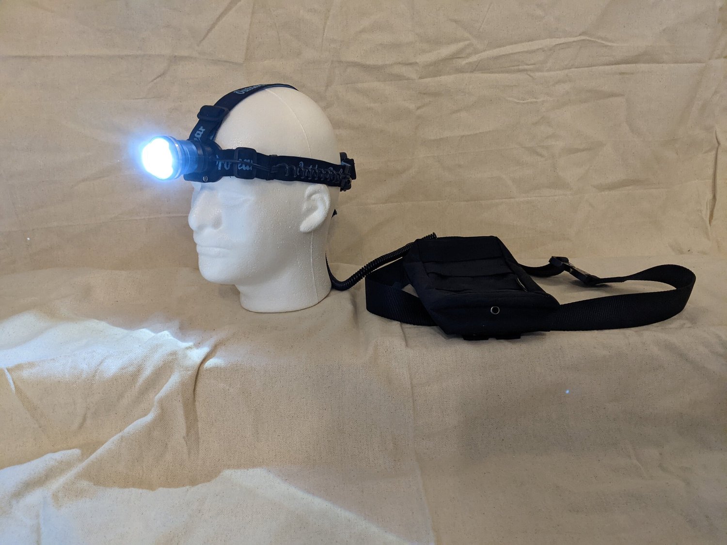
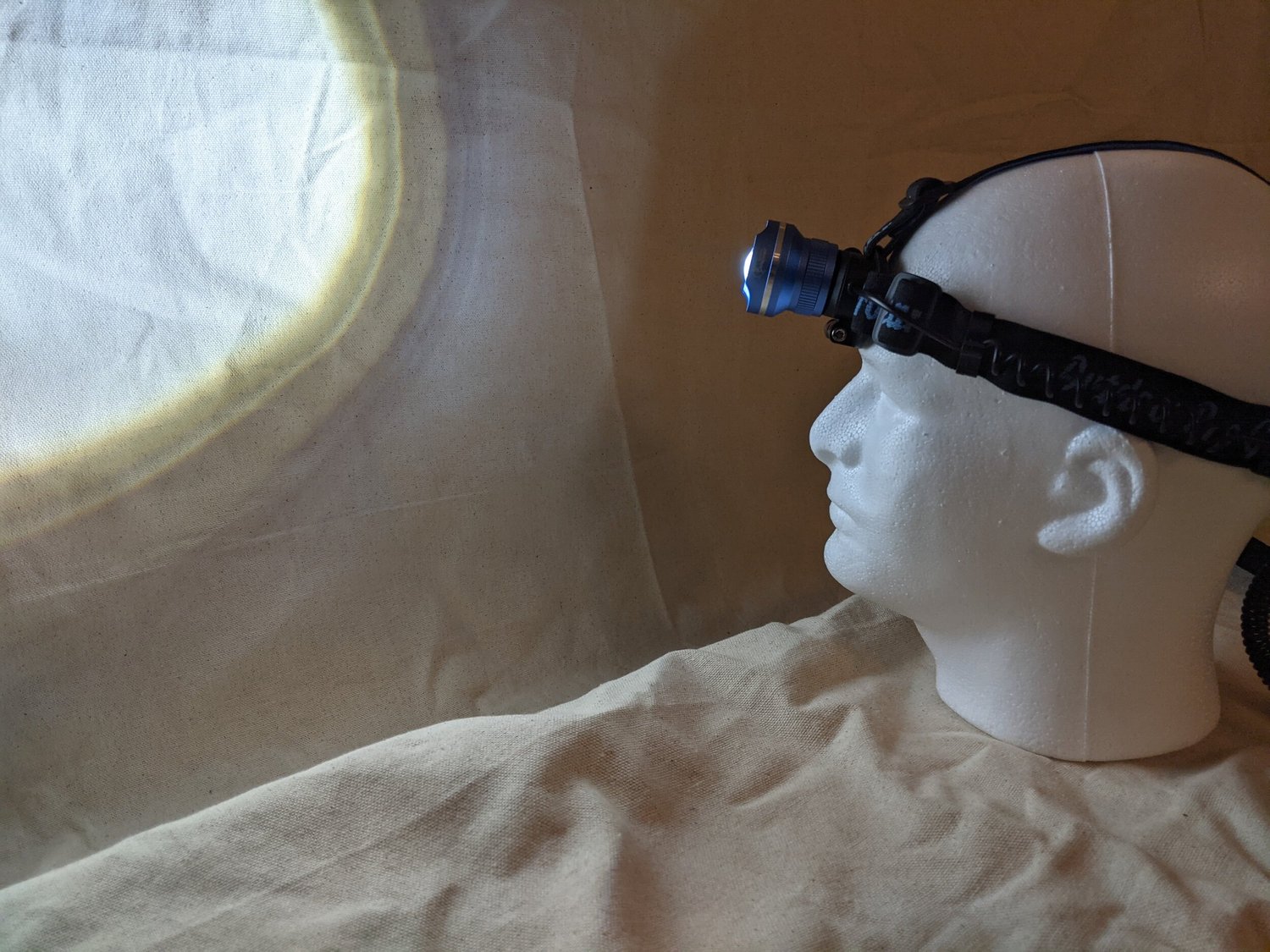
Headlamp battery modificationA headlamp with a larger battery supplyI liked this headlamp’s bright LED, but its small original batteries limited how long I could use it. I adapted it to draw from a larger battery bank, with the aim of extending its runtime. It was a simple packaging and power-supply modification to a light I already enjoyed using.
Personal project
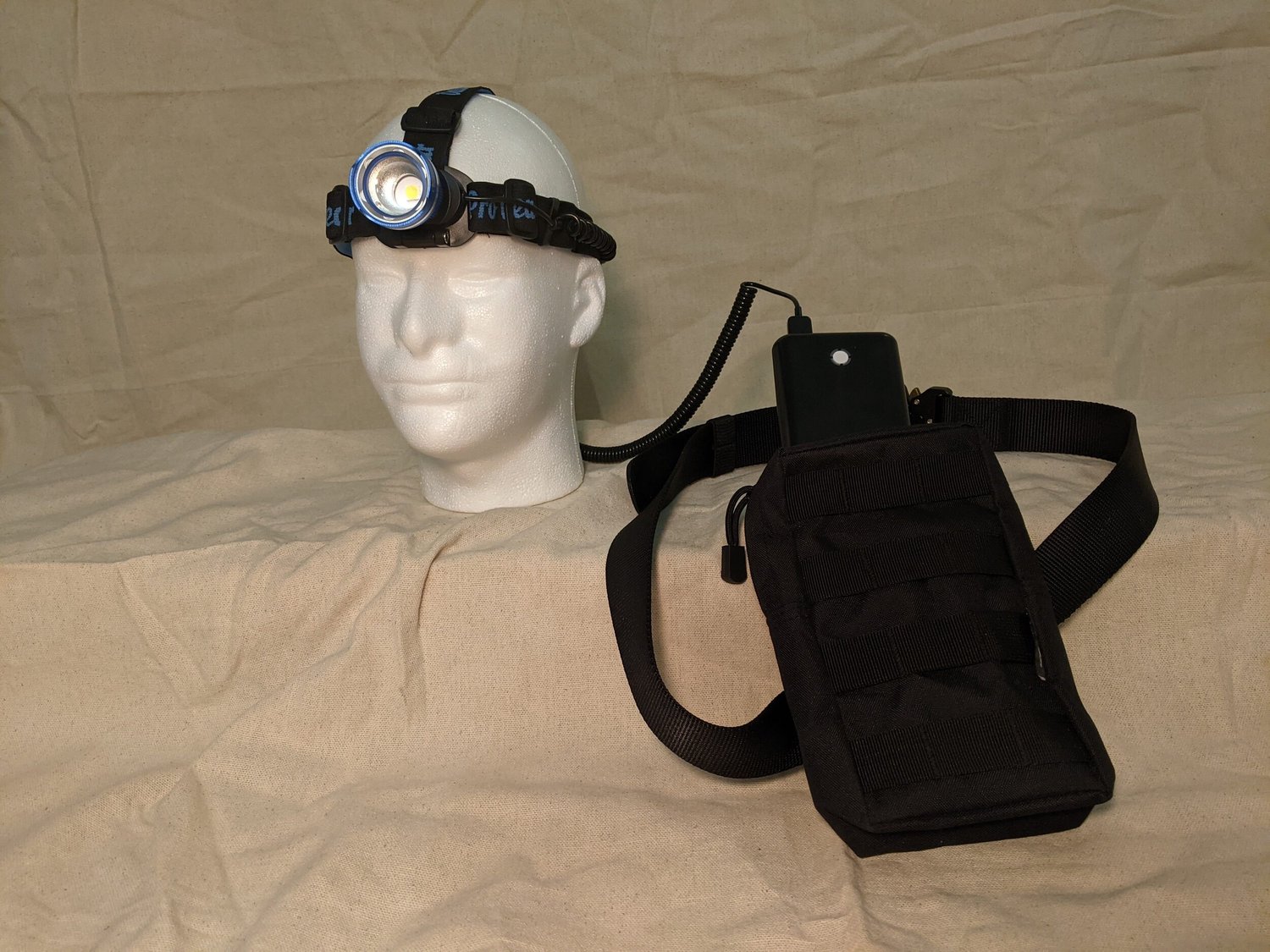
Headlamp battery modificationAnother view of the headlamp modificationAnother view of the headlamp and its larger power source. My goal was longer use between battery changes, especially for situations where a hands-free light would be needed for an extended period.
Personal project
Headlamp battery modificationThe modified headlamp assemblyA further view of the battery-bank headlamp project. This was a small practical modification focused on runtime, rather than a redesign of the lamp’s optics or LED.
Personal project
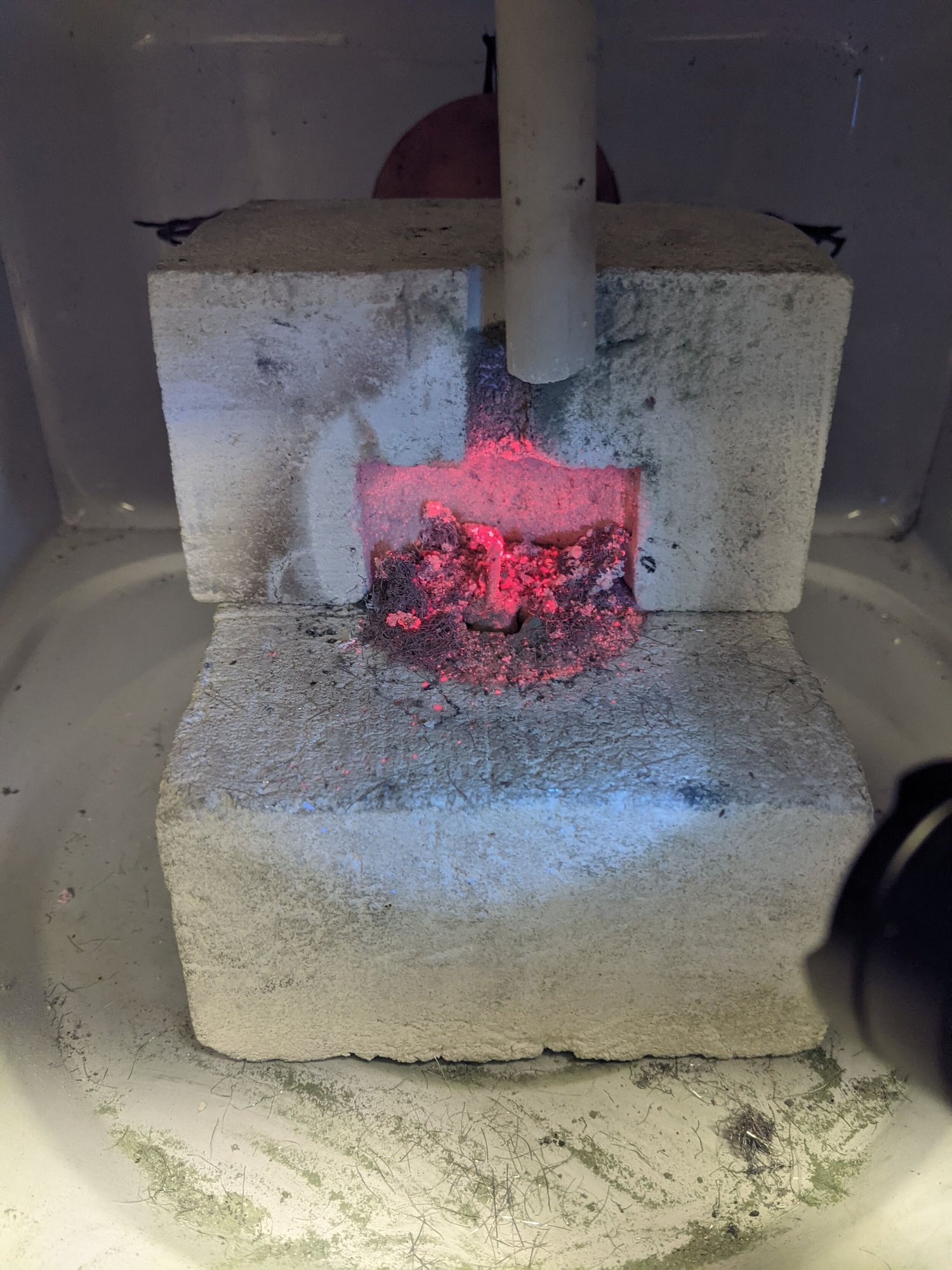
Microwave-plasma furnaceExploring microwave plasma as a heat sourceAn experimental attempt to use microwave-excited plasma as the heat source for ruby-growth trials. I recovered small fluorescent pieces that I interpreted as ruby, but the heating process was difficult to control. This remained an exploratory prototype with unresolved questions about containment and repeatability.
Personal project
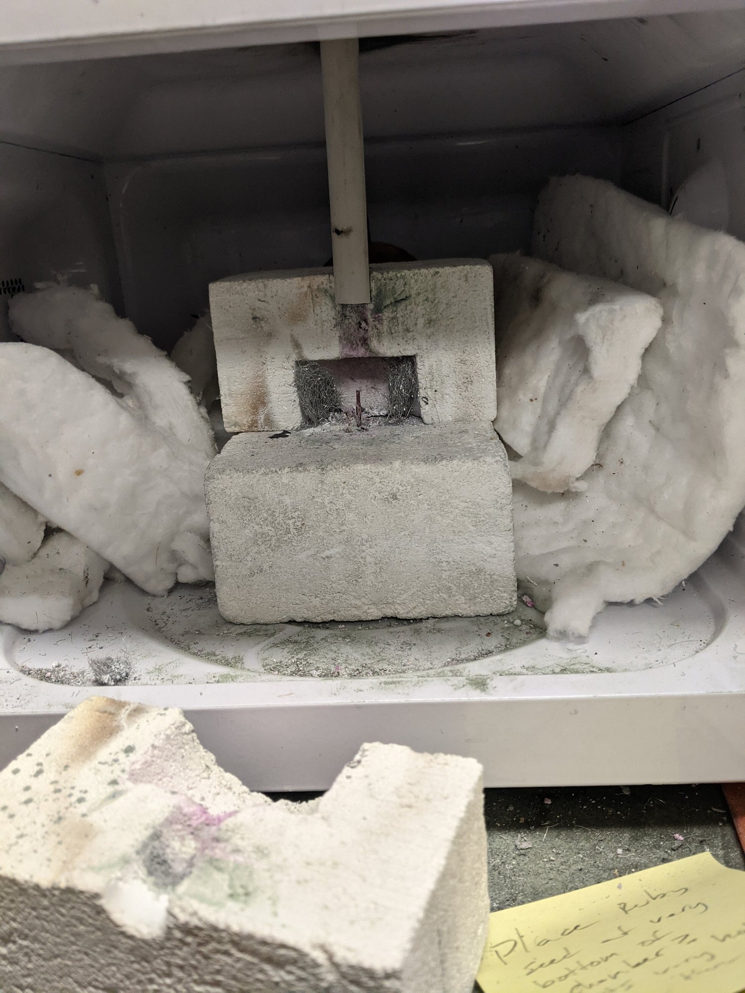
Microwave-plasma furnaceThe furnace’s insulating materialsA view inside the experimental microwave furnace, showing firebrick and high-temperature ceramic insulation. These materials were part of my effort to retain heat around the small reaction chamber during the early trials.
Personal project
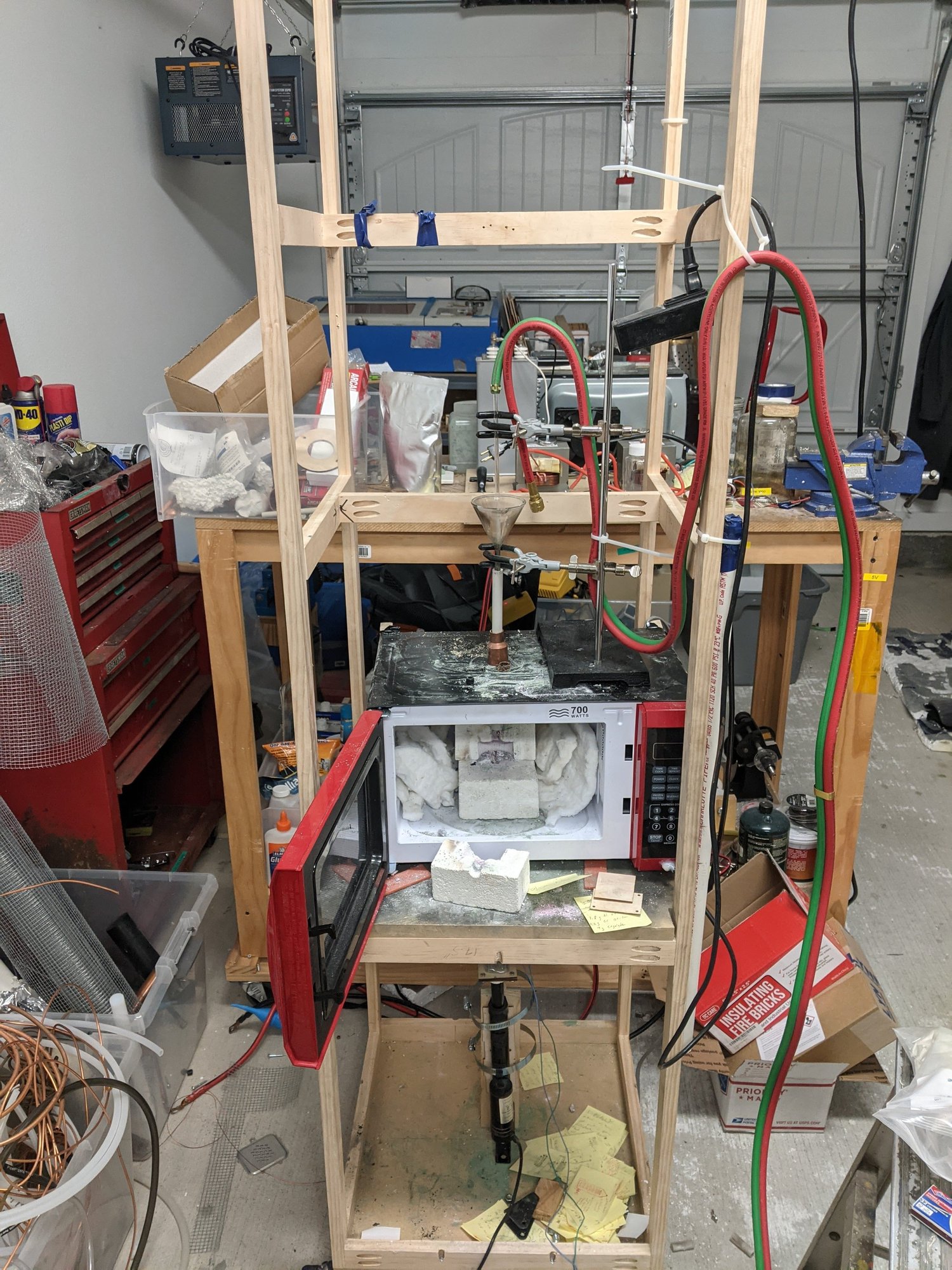
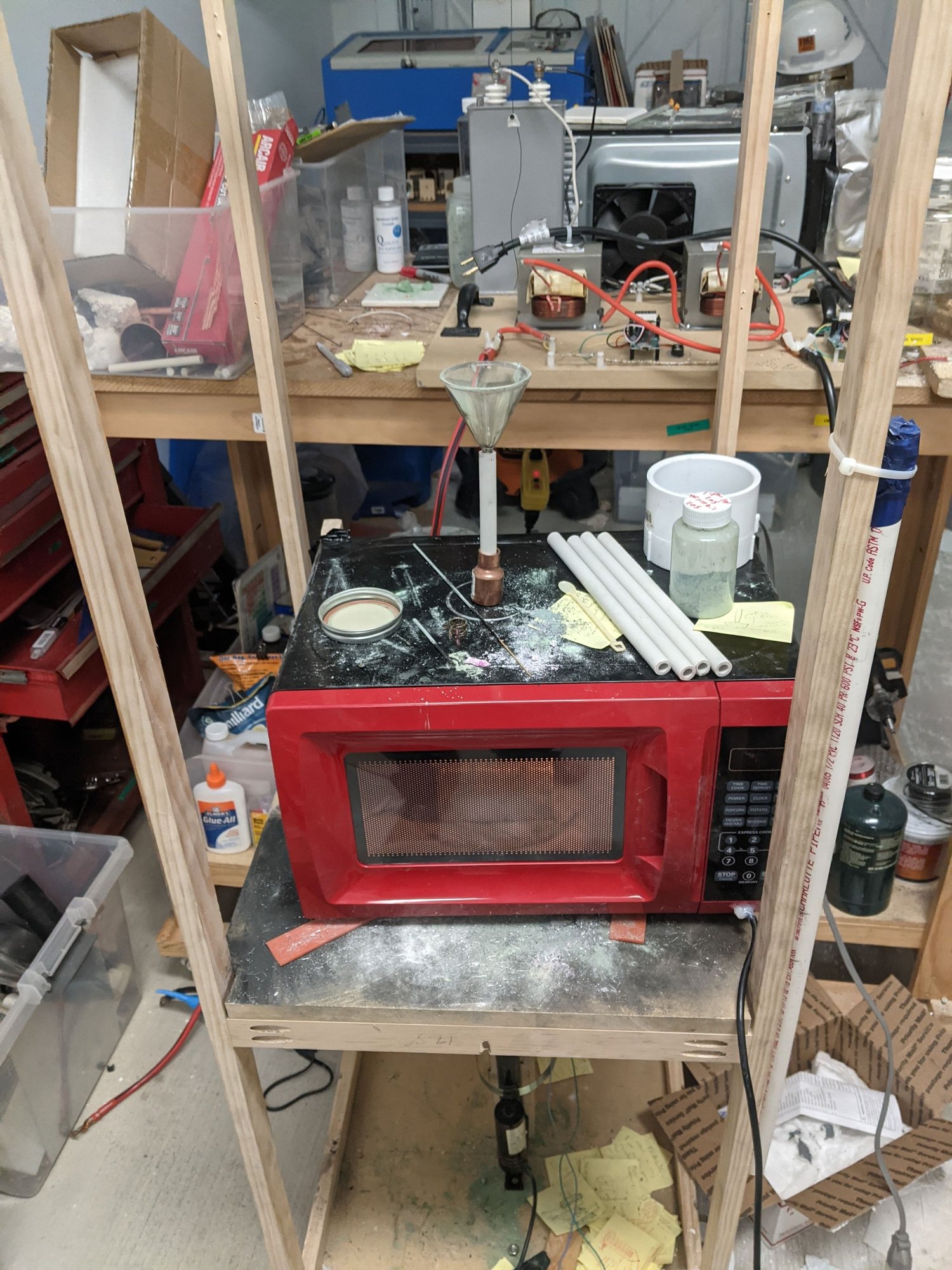
Microwave-plasma furnaceThe experimental furnace assemblyThe complete prototype, including the external feed hardware visible above the enclosure. I was exploring a way to introduce the sample material during heating, but the process still needed much better control.
Personal project
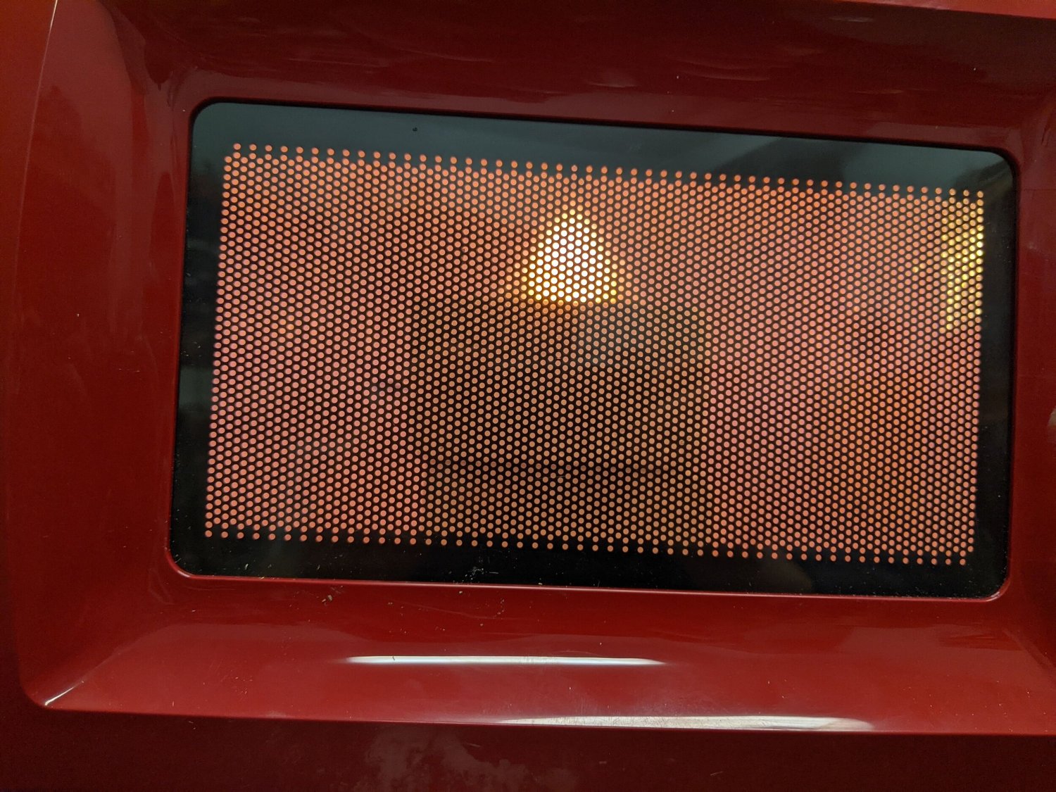
Microwave-plasma furnaceAn exterior view of the prototypeAnother view of the microwave-furnace experiment with the door closed. The photographs record an early prototype in the wider series of trials exploring different heat sources for crystal-growth experiments.
Personal project
Microwave-plasma furnaceA bright plasma during a containment trialThe bright glow from a trial using an inverted borosilicate-glass funnel. I wanted the heat concentrated within the refractory chamber, but this arrangement exposed the limitations of the containment approach. It was one of several early experiments that still needed better control.
Personal project
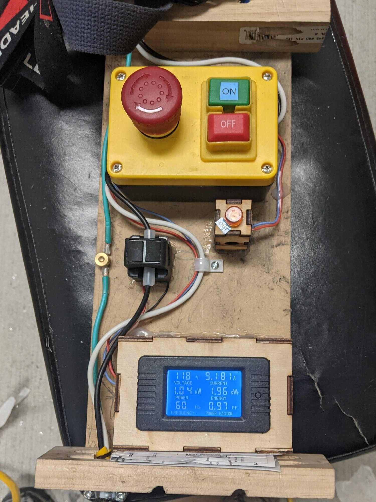
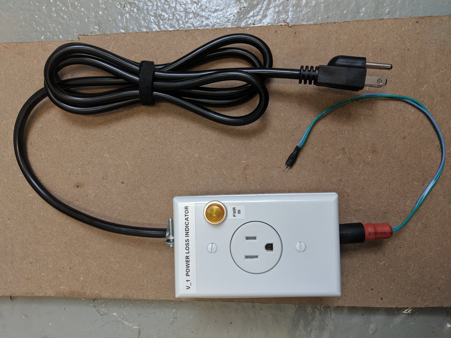
Bench power meter and off switchPower monitoring with a prominent off buttonA control box I made for my experiments, combining a readily accessible off button with a power meter. I wanted a convenient way to switch off the connected equipment and see how much electrical power it was using.
Personal project
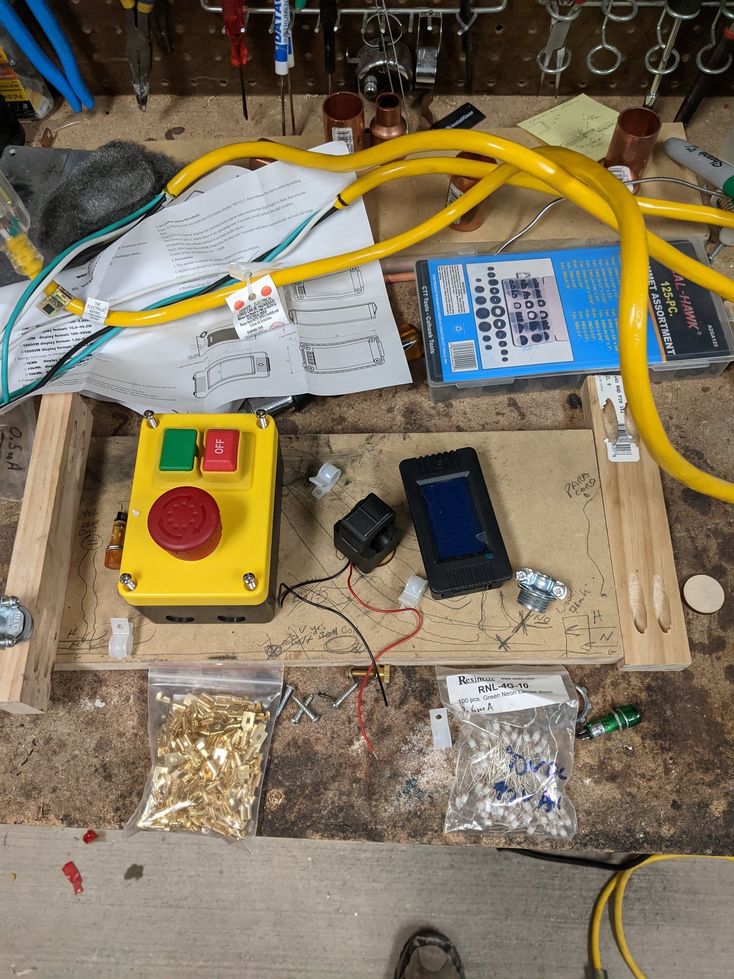
Bench power meter and off switchThe power-control box before assemblyThe components of the power-monitoring and shutoff box before final assembly. This view records the work of bringing the controls and meter together in one enclosure.
Personal project
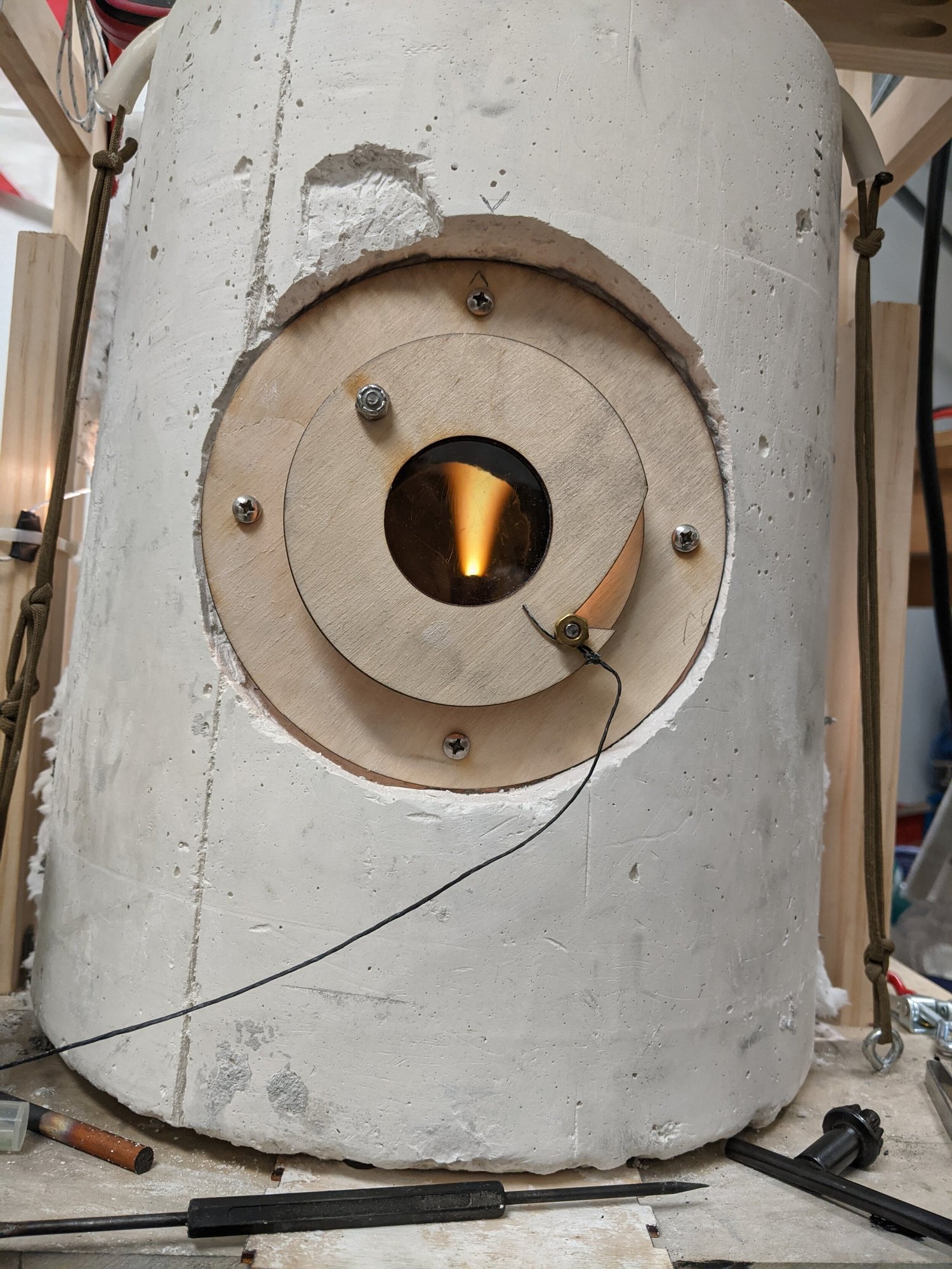
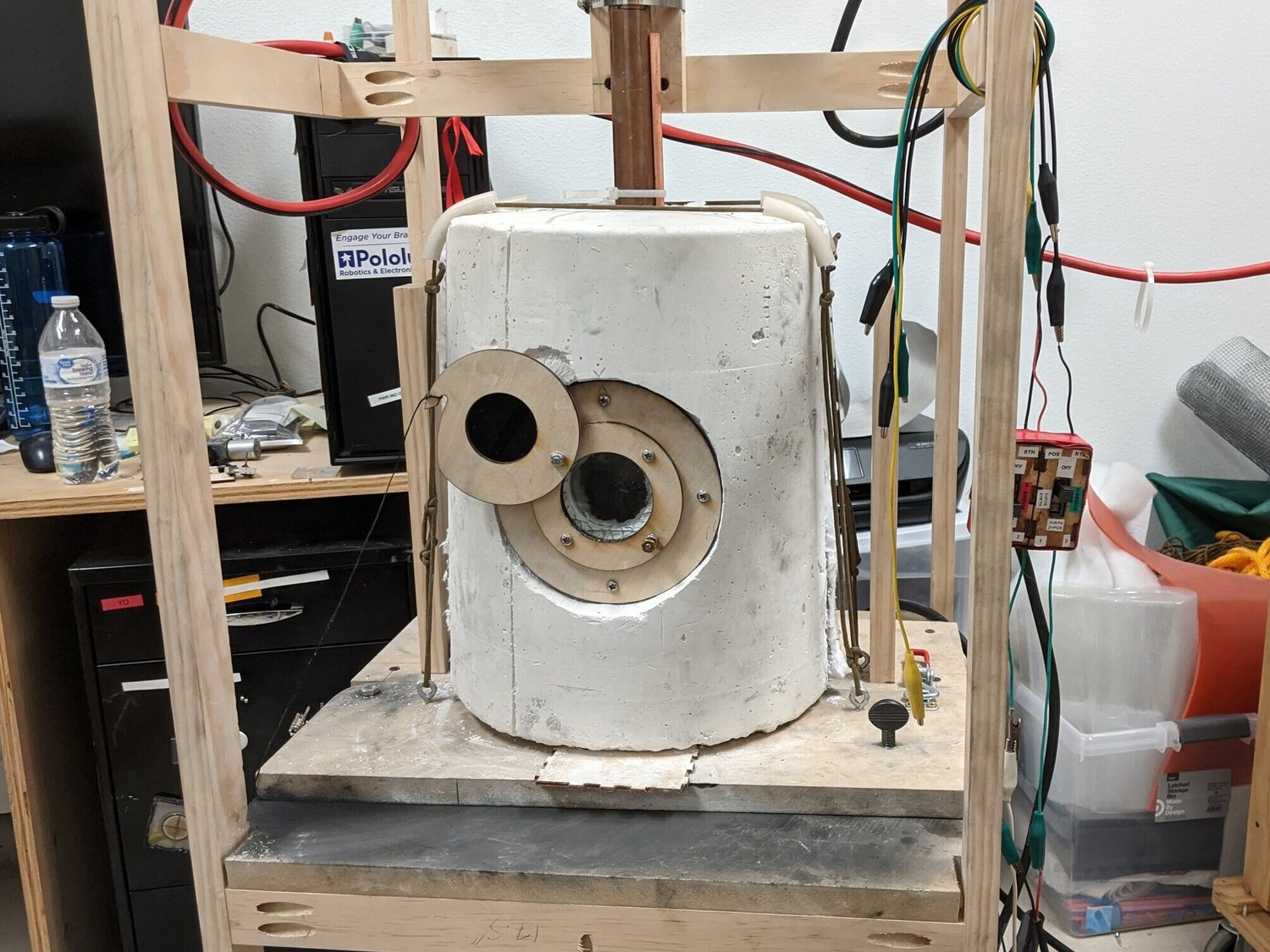
Electric-arc ruby furnaceAn electric-arc furnace for crystal-growth trialsAn attempt to explore a flame-fusion-style process using an electric arc as the heat source. I made a split enclosure from plaster mixed with vermiculite and added ceramic-wool insulation inside. The design included a feed opening above the chamber and a small front viewing port.
Personal project
Electric-arc ruby furnaceThe furnace’s front viewing portA closer view of the small opening used to observe the furnace interior. I fitted welding filter glass in front of it to reduce the brightness of the view during the arc experiments.
Personal project
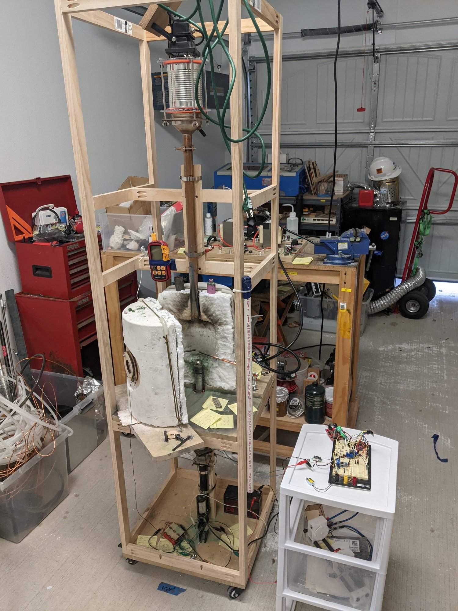
Electric-arc ruby furnaceThe split chamber and powder-feed assemblyThe complete furnace assembly with its enclosure opened for access. Above it, a reservoir and long copper tube formed an experimental powder feeder. I was exploring how to introduce small amounts of alumina into the heated region during a crystal-growth trial.
Personal project
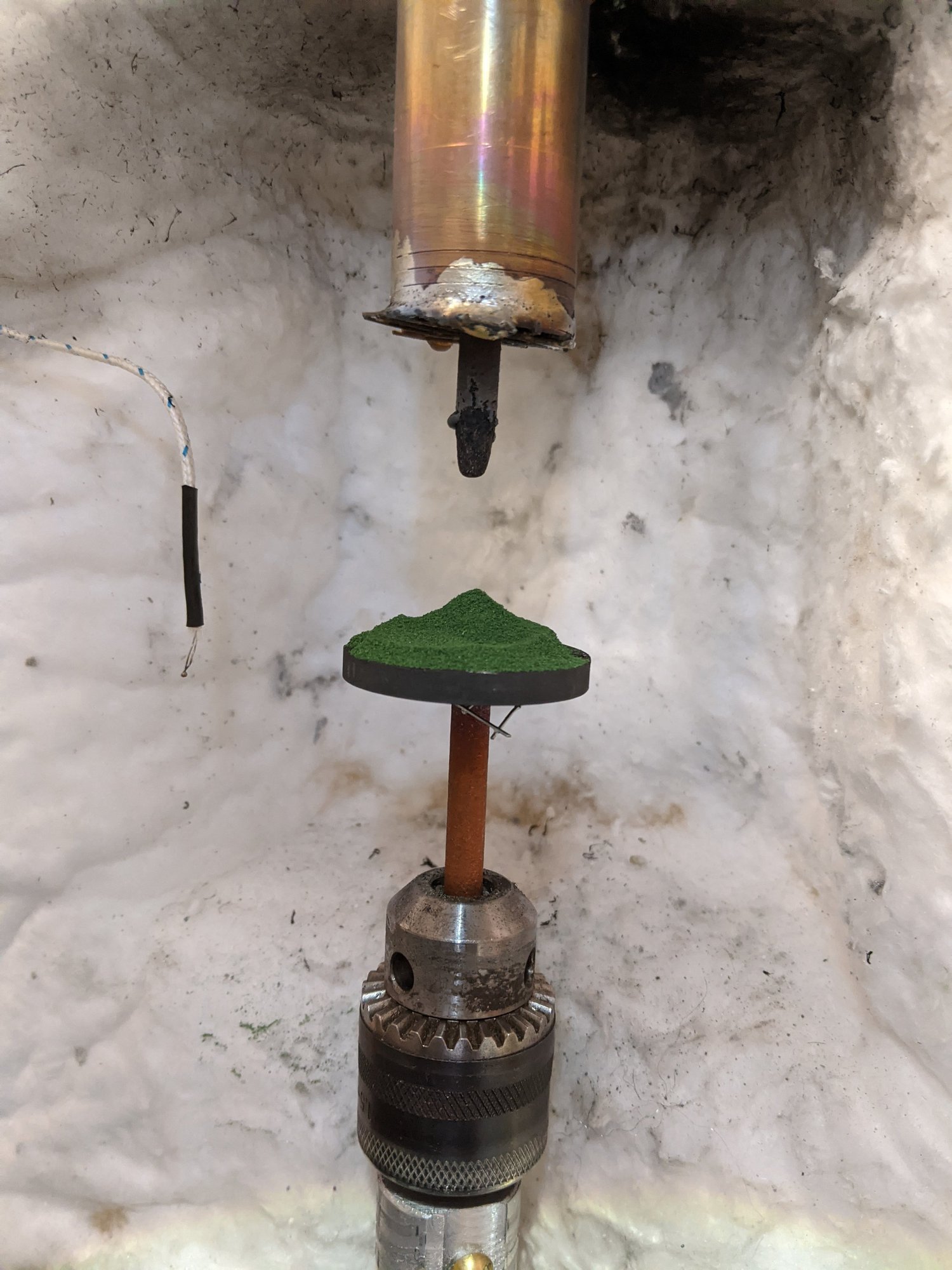
Electric-arc ruby furnaceA replaceable sample holder with lift and rotationOne arc-heating arrangement positioned an electrode above a graphite platform holding the oxide feedstock. A collet—a small clamping holder—made the head replaceable. The supporting mechanism could rotate and move vertically, letting me explore different sample positions during the furnace experiments.
Personal project
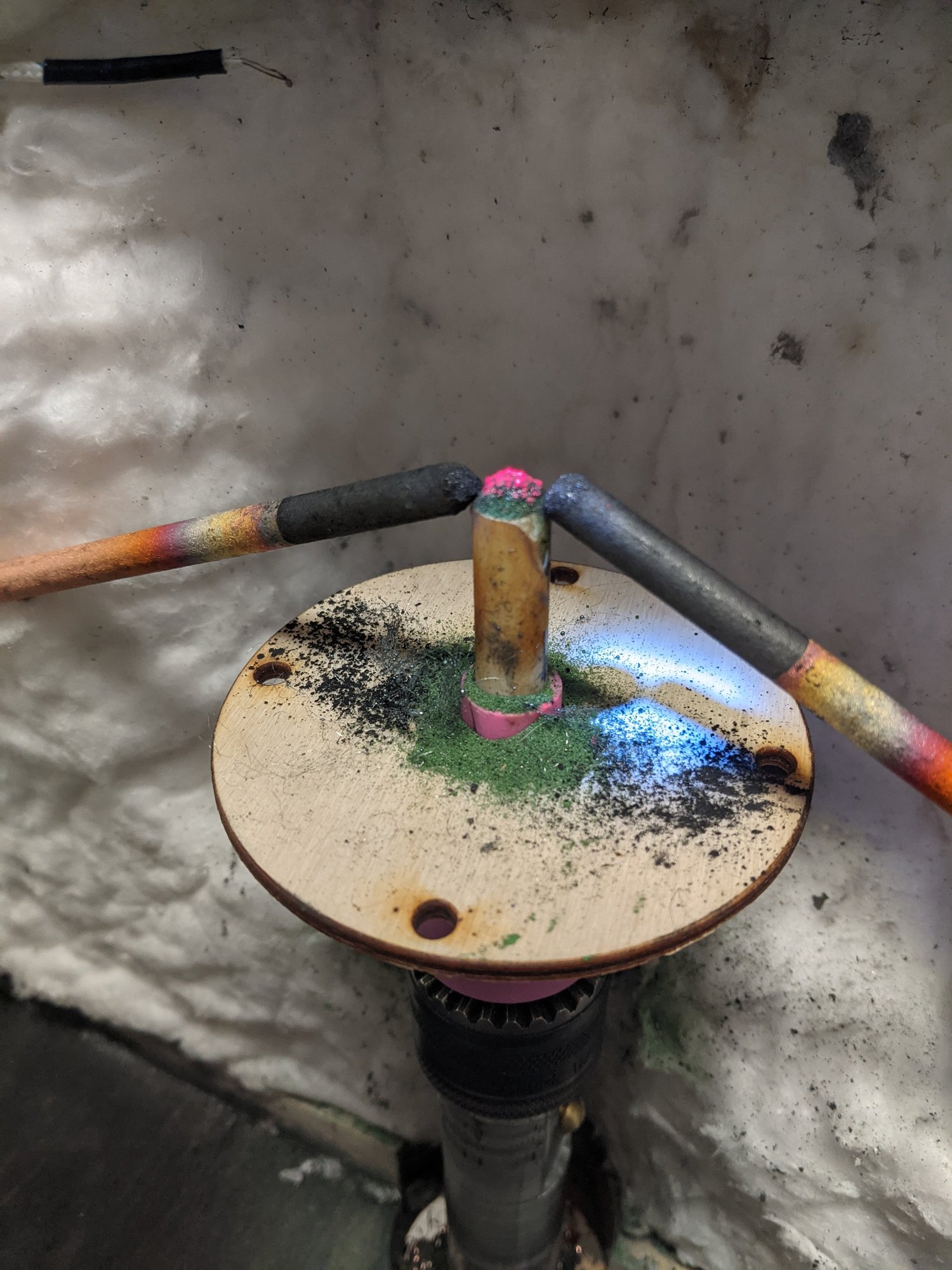
Electric-arc ruby furnaceAnother carbon-arc heating trialAn experiment using an arc between two carbon electrodes as the heat source for a sapphire-growth attempt. This was one of several heating arrangements I explored while developing the furnace.
Personal project
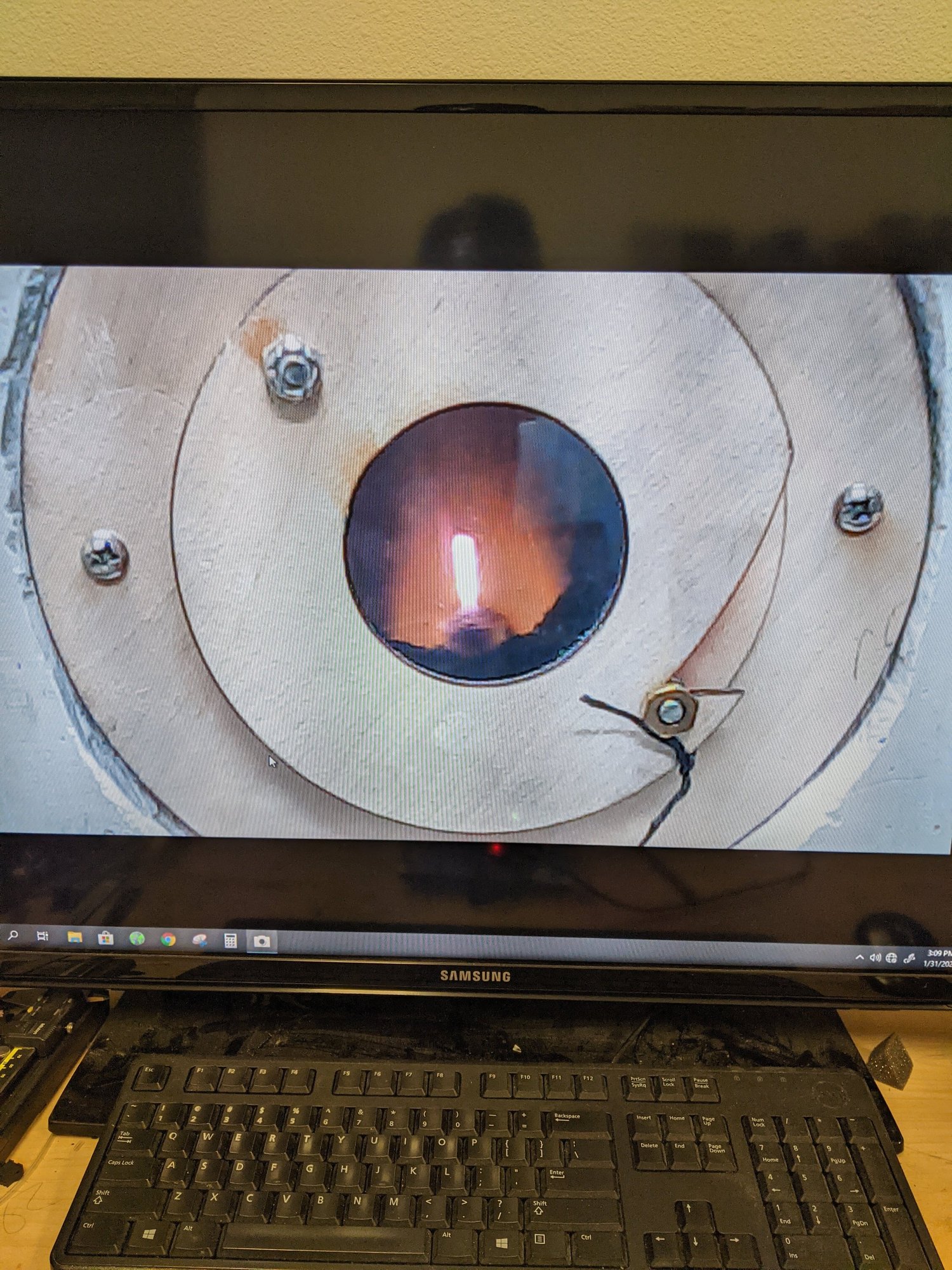
Electric-arc ruby furnaceWatching the furnace through a cameraA video camera aimed at the front of the furnace let me monitor the experiment remotely. The bright central target is a ruby seed crystal attached to a porcelain rod, intended to provide a starting point for growth.
Personal project
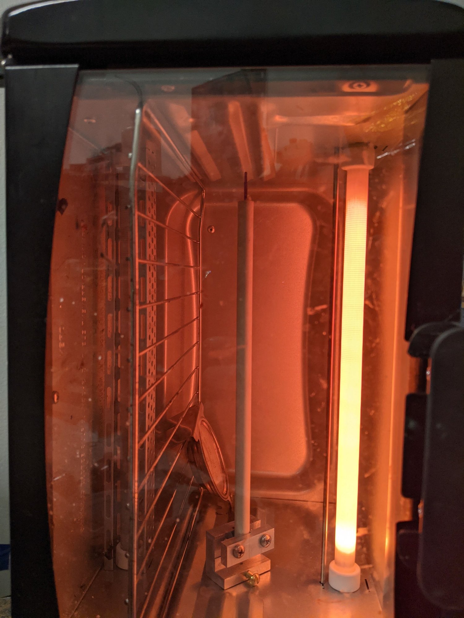
Electric-arc ruby furnaceThe ruby seed and its ceramic supportThe ruby seed crystal mounted on its ceramic support rod. This assembly was intended to hold the seed in the heated region as additional material was introduced during a growth experiment.
Personal project
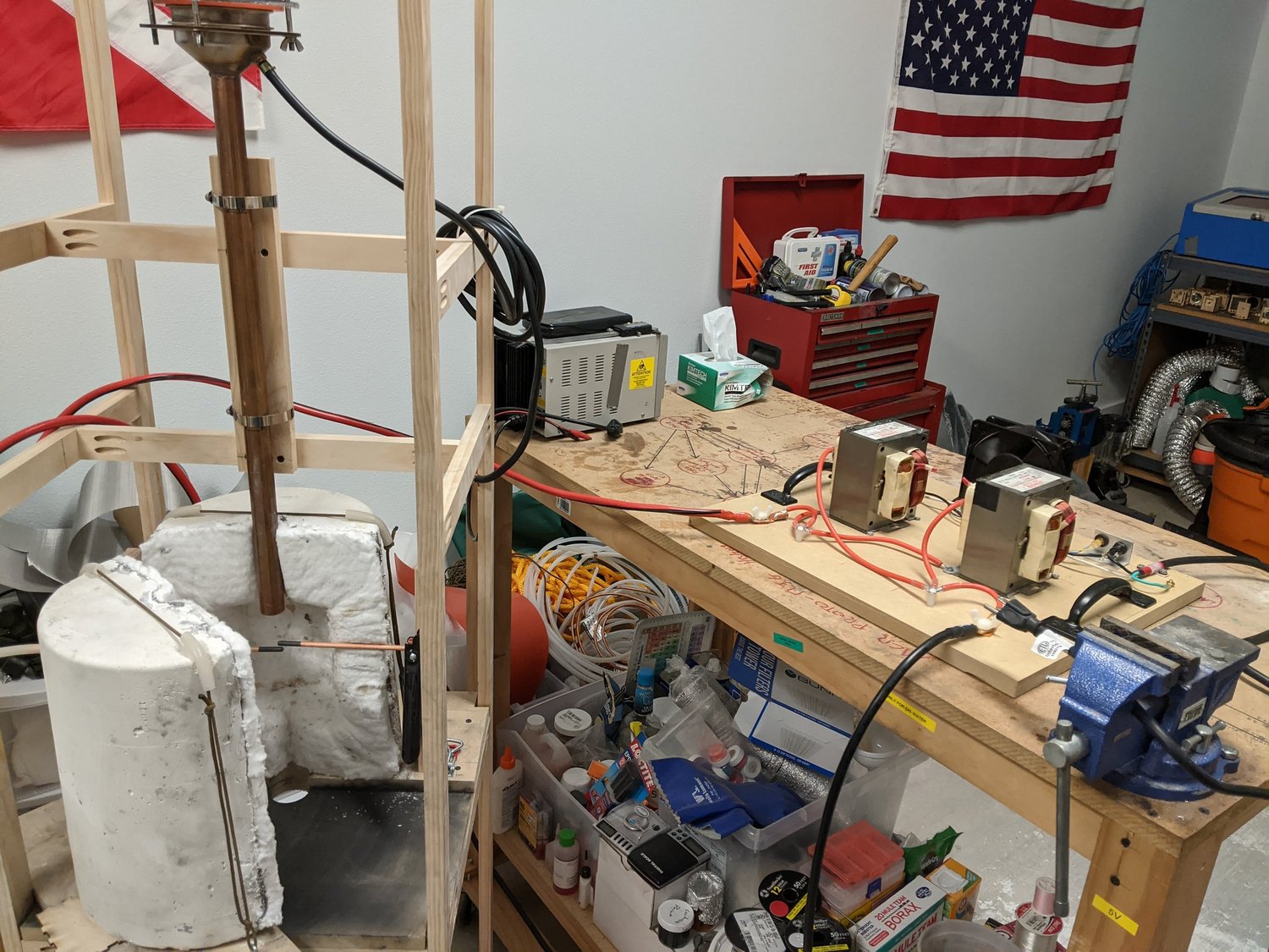
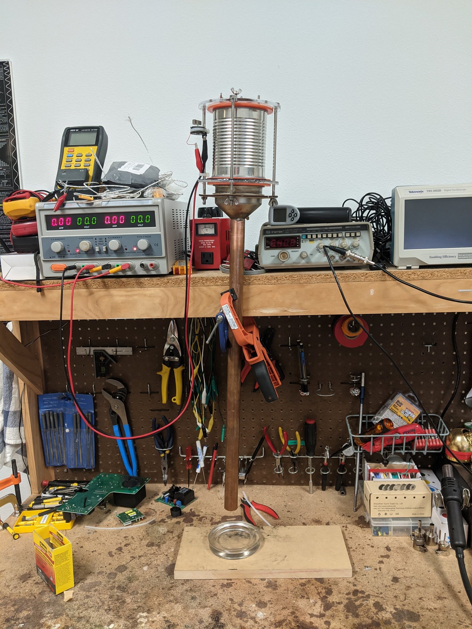
Electric-arc ruby furnaceThe arc furnace during constructionA construction-stage view of the furnace and supporting equipment. The two microwave-oven transformers on the right were part of the experimental arc power source. The photograph records the assembly before the later enclosure and monitoring arrangements were complete.
Personal project
Electric-arc ruby furnaceTesting the powder feederA test of the reservoir, fine mesh, and feed tube intended to deliver small quantities of alumina to the furnace. Developing a manageable powder feed was a separate part of the project alongside the heating and sample-positioning systems.
Personal project
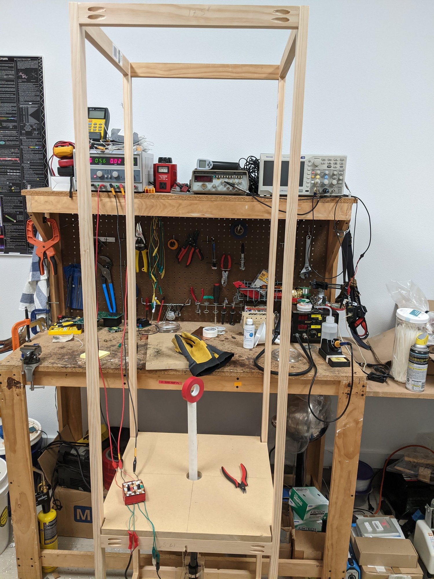
Electric-arc ruby furnaceBuilding the support frameThe wooden frame under construction. It provided a structure for mounting the chamber and the other mechanical parts of the furnace experiment.
Personal project
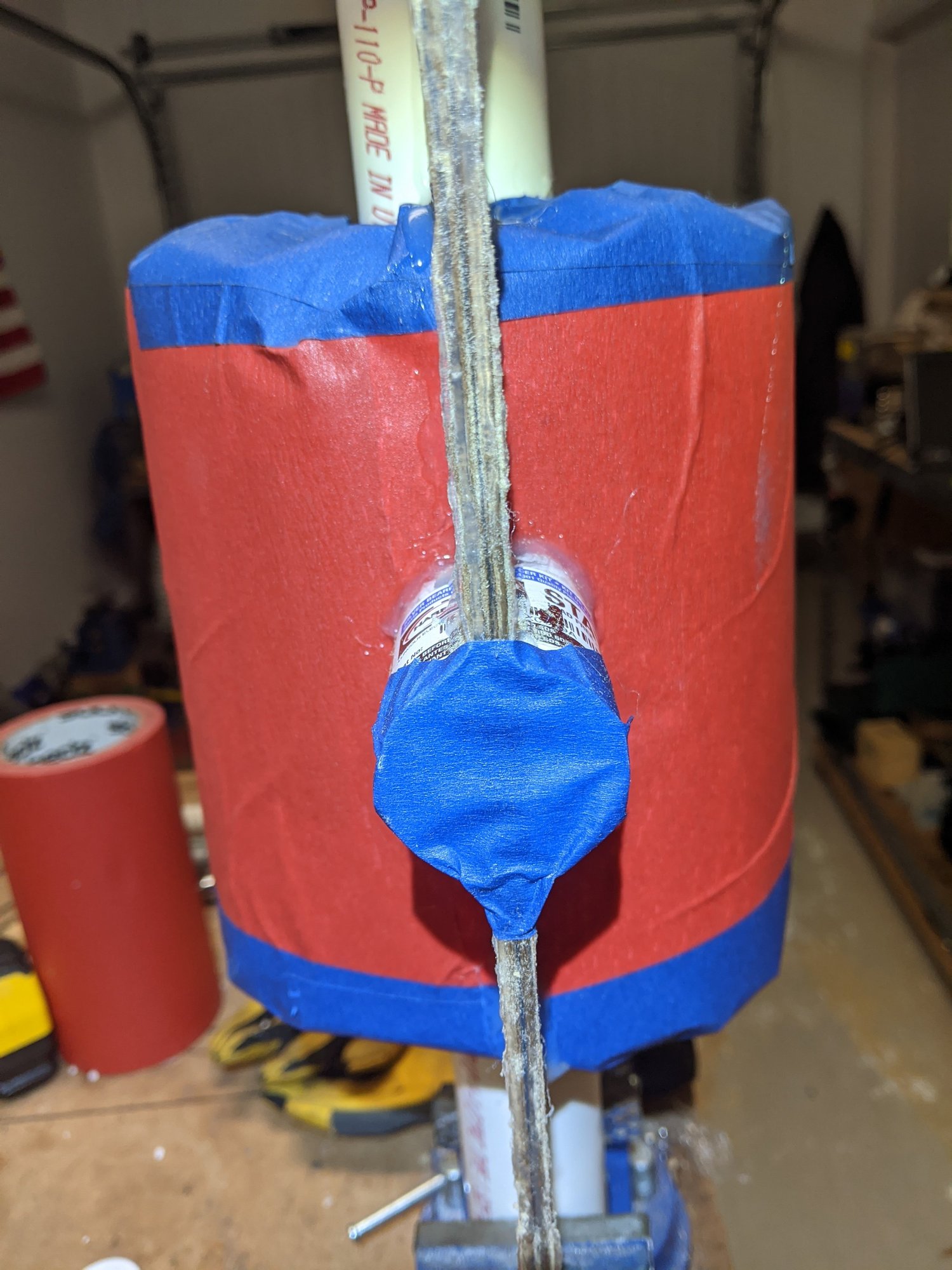
Electric-arc ruby furnaceMaking the chamber moldThe form used to define the inside of the plaster furnace enclosure. I added wire mesh as reinforcement while developing the mold and casting arrangement for the two chamber halves.
Personal project
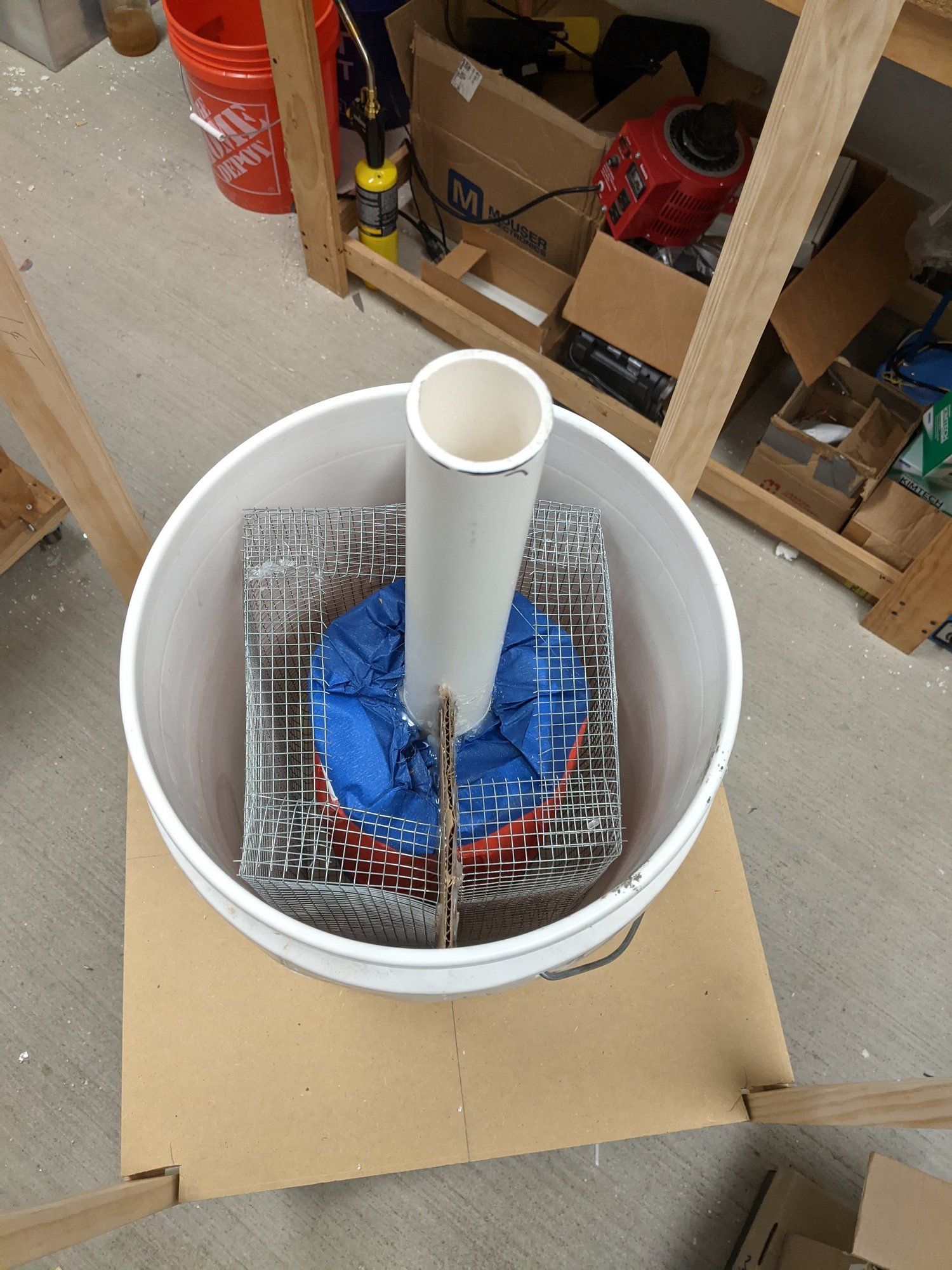
Electric-arc ruby furnaceCasting the enclosureThe enclosure mold inside a bucket used as the outer casting form. The inner form defined the chamber cavity, while the plaster mixture filled the space around it to create the shell.
Personal project
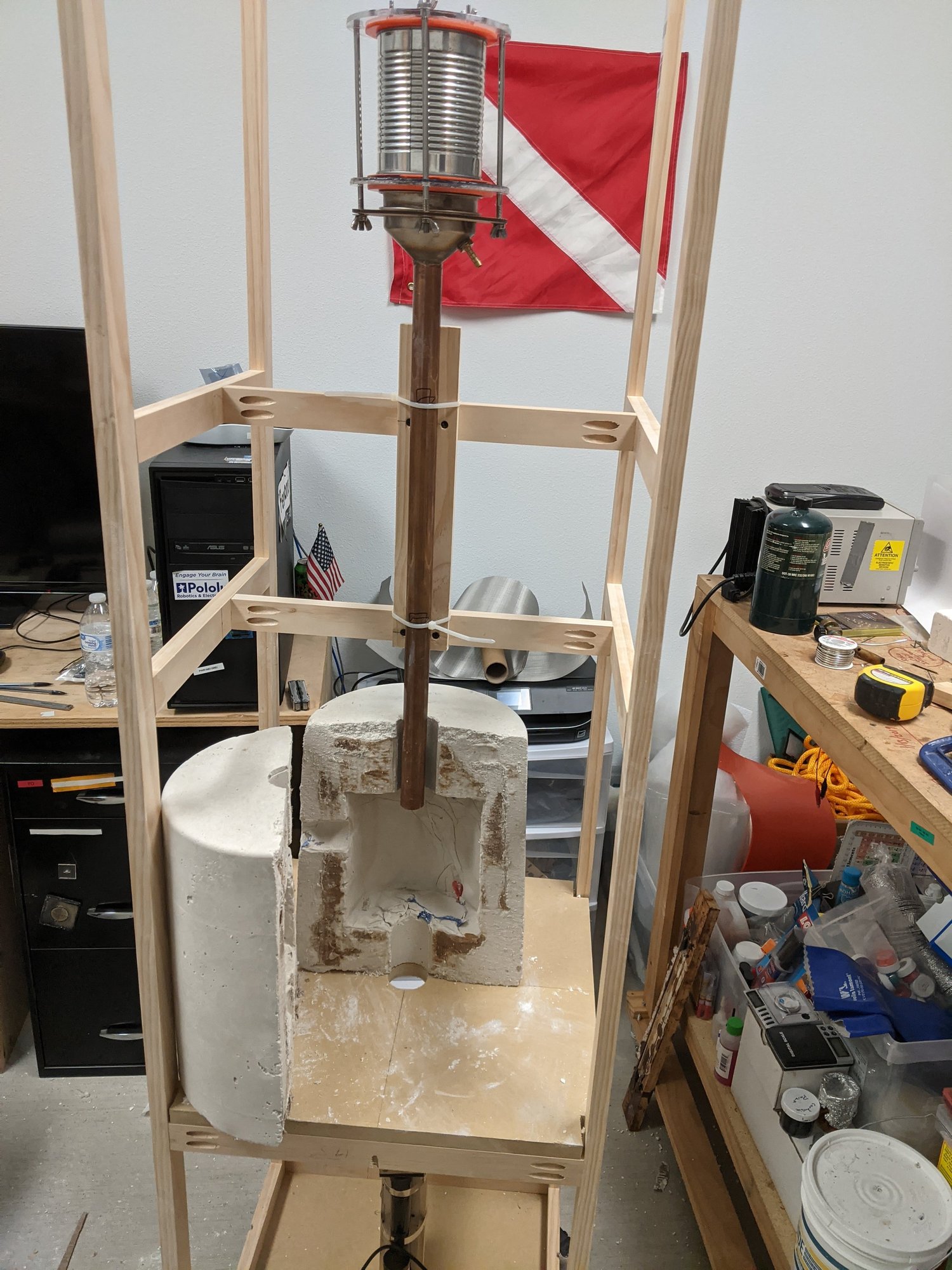
Electric-arc ruby furnaceThe two cast chamber halvesThe plaster enclosure after the casting forms were removed. The two halves enclose a central cavity and can be opened to reach the experimental heating and sample-holder components.
Personal project
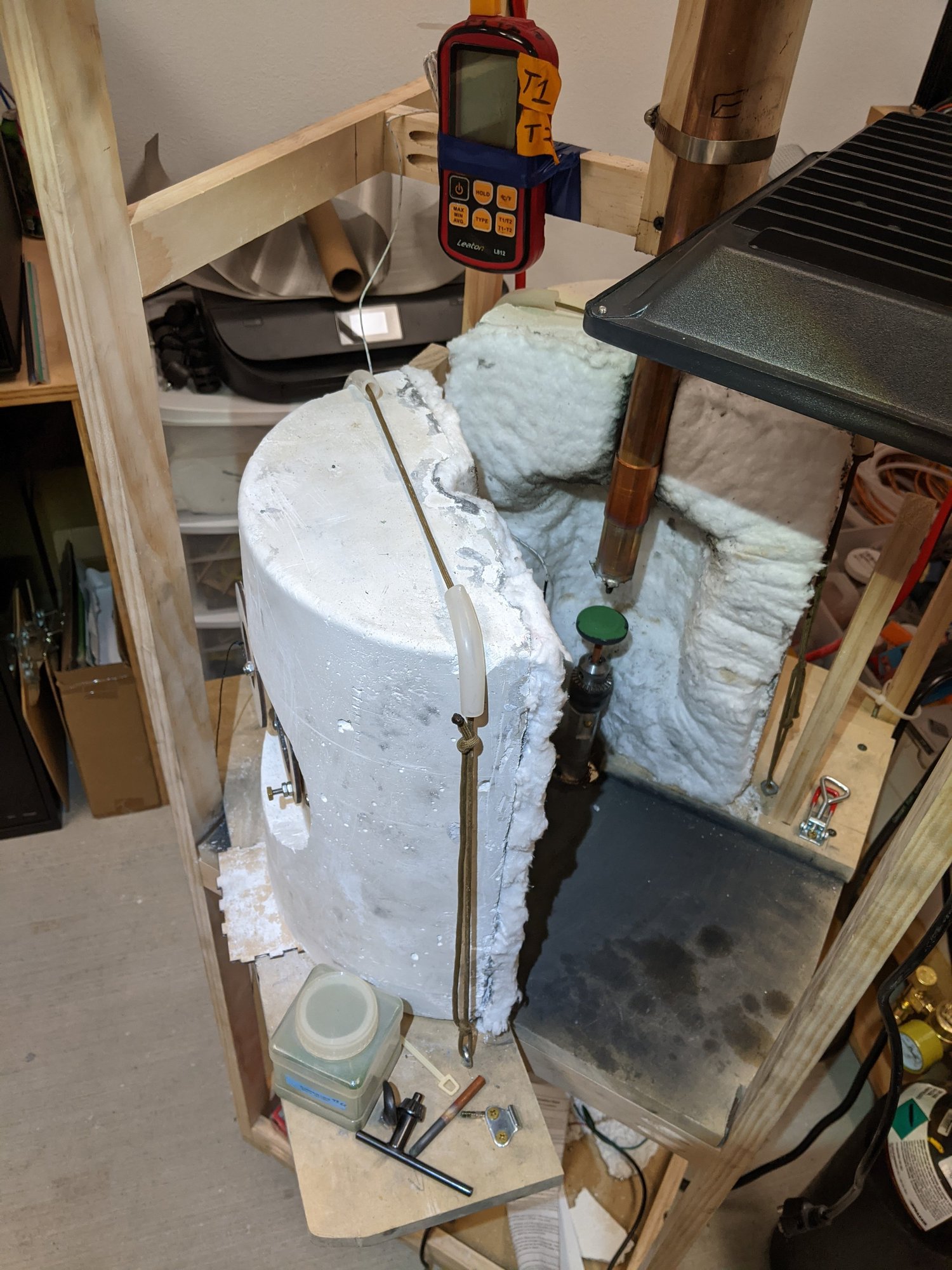
Electric-arc ruby furnaceAdding the inner insulationCeramic wool lining the inside of the two cast chamber halves. This was an additional insulation layer intended to help retain heat around the experimental furnace’s working region.
Personal project
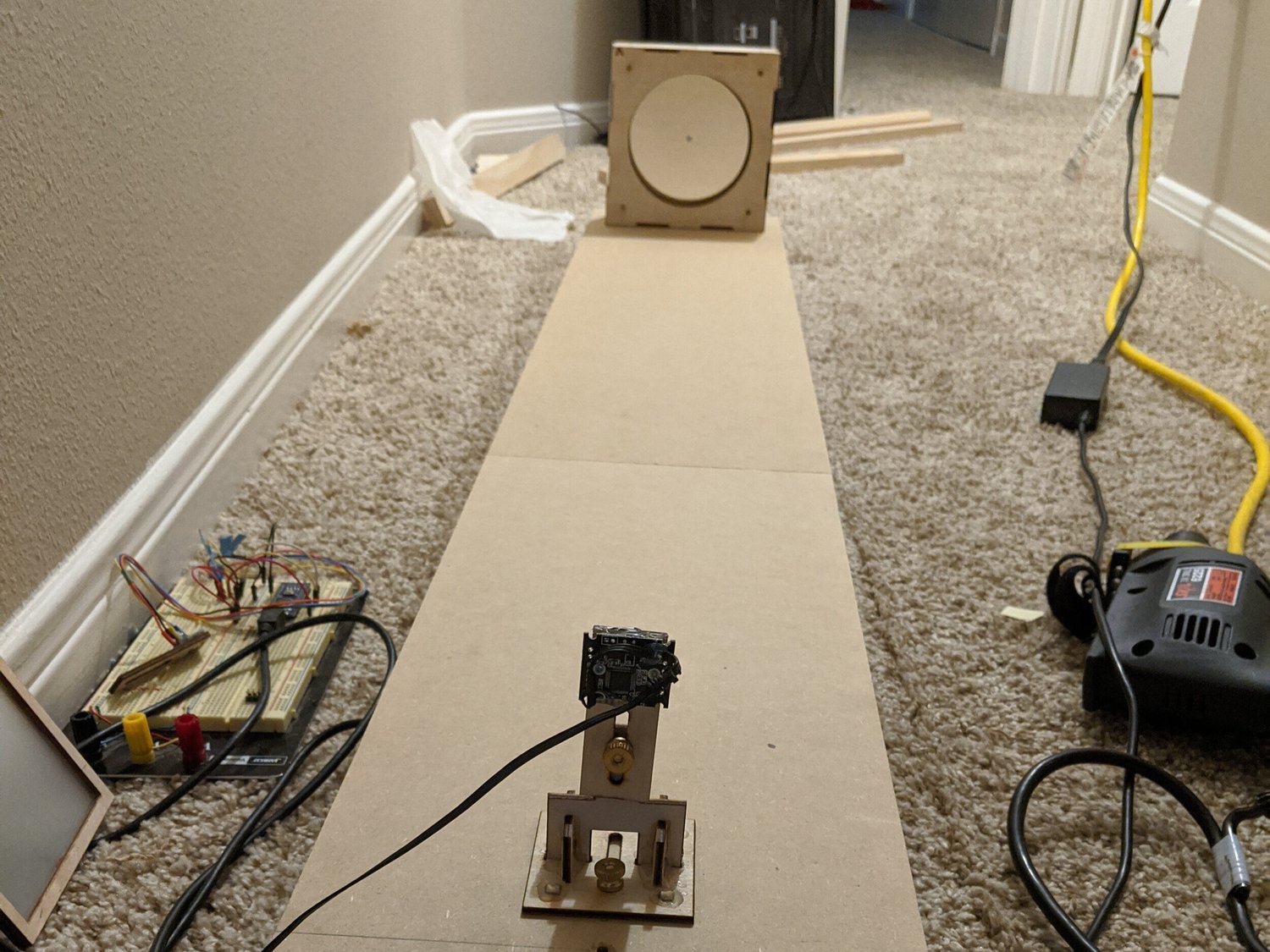
Mirror telescope experimentA webcam and mirror optics experimentAn experimental optical setup with a small webcam in the foreground and a slightly concave first-surface mirror behind it. I was exploring how to capture a distant target with the mirror and camera, using a simple adjustable structure.
Personal project
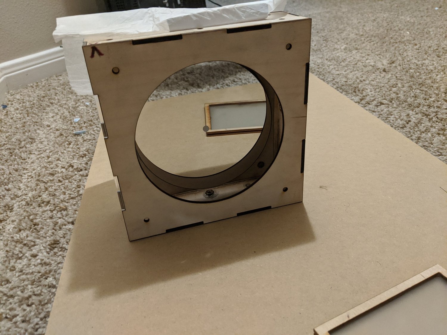
Mirror telescope experimentThe concave mirrorA closer view of the curved mirror used in the camera experiment. Its reflective coating is on the front surface, and the curvature was used to bring light from the target toward the imaging arrangement.
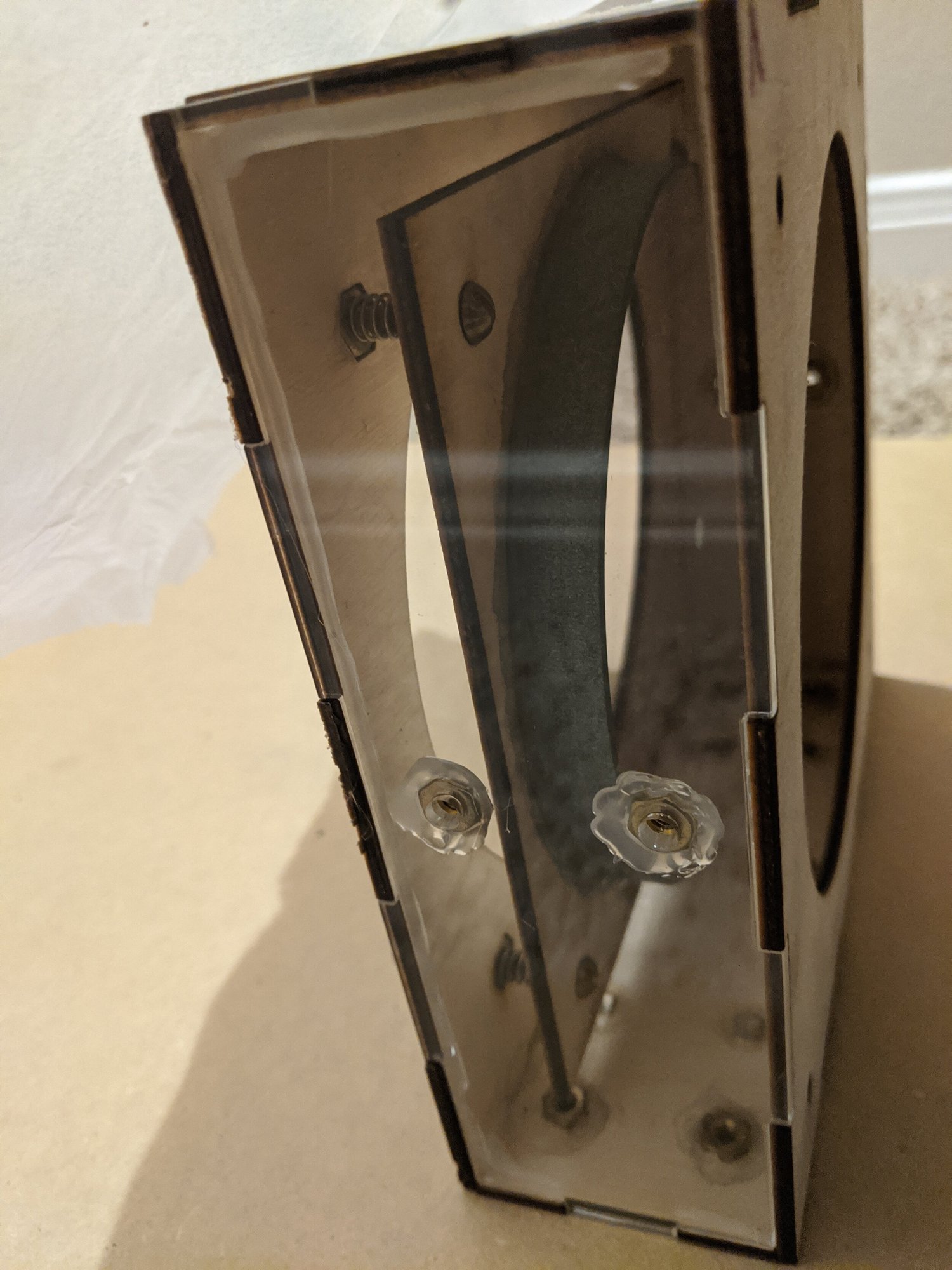
Personal project
Mirror telescope experimentFine adjustment of the mirror positionThe mirror sits in an adjustable mount inside the box. Several small screws let me make fine changes to its position and alignment while setting up the optical path.
Personal project
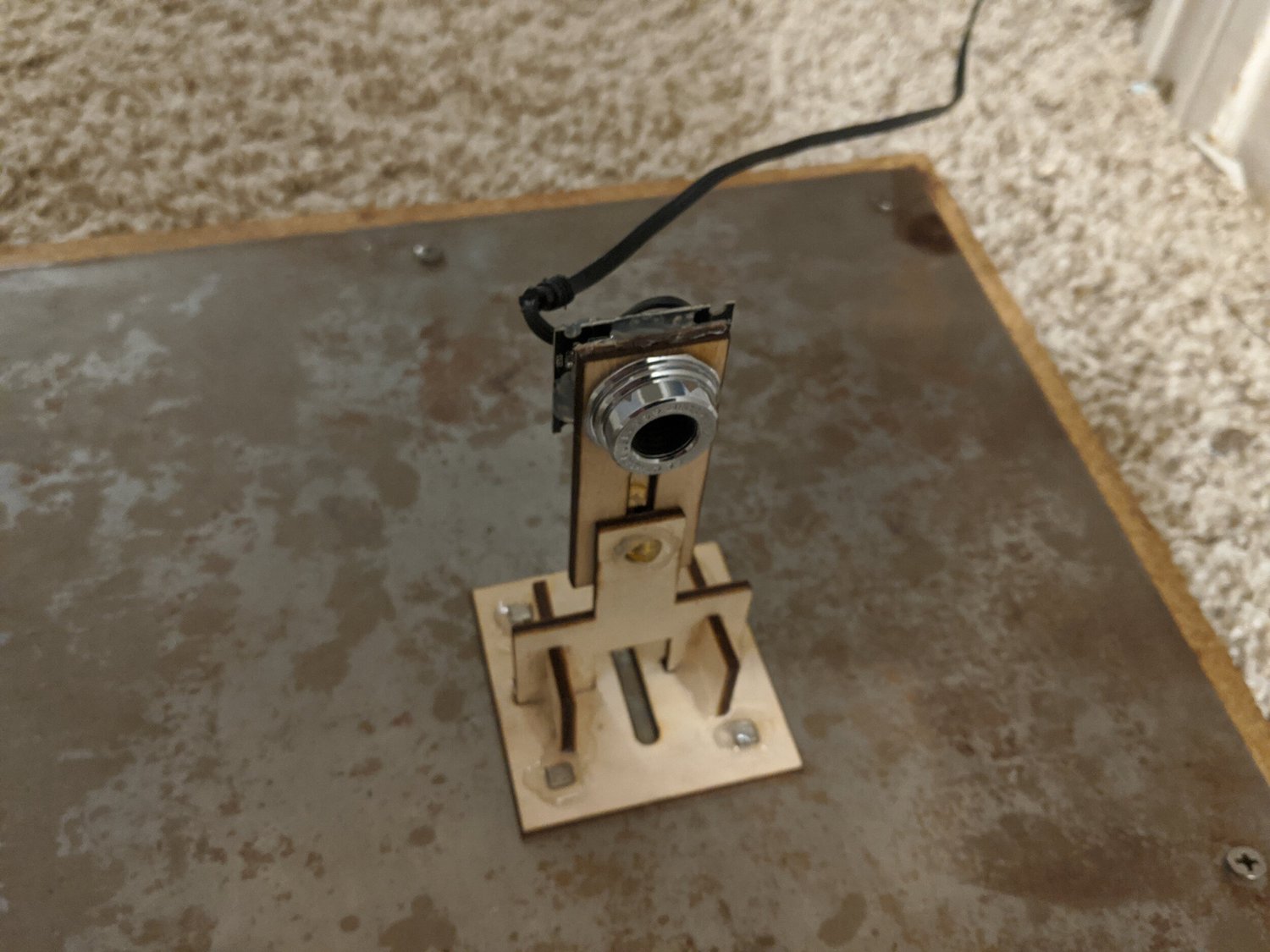
Mirror telescope experimentThe camera used for the testThe webcam used to capture the view through the experimental optics. It gave me a way to inspect the image on a computer while adjusting the mirror and camera arrangement.
Personal project
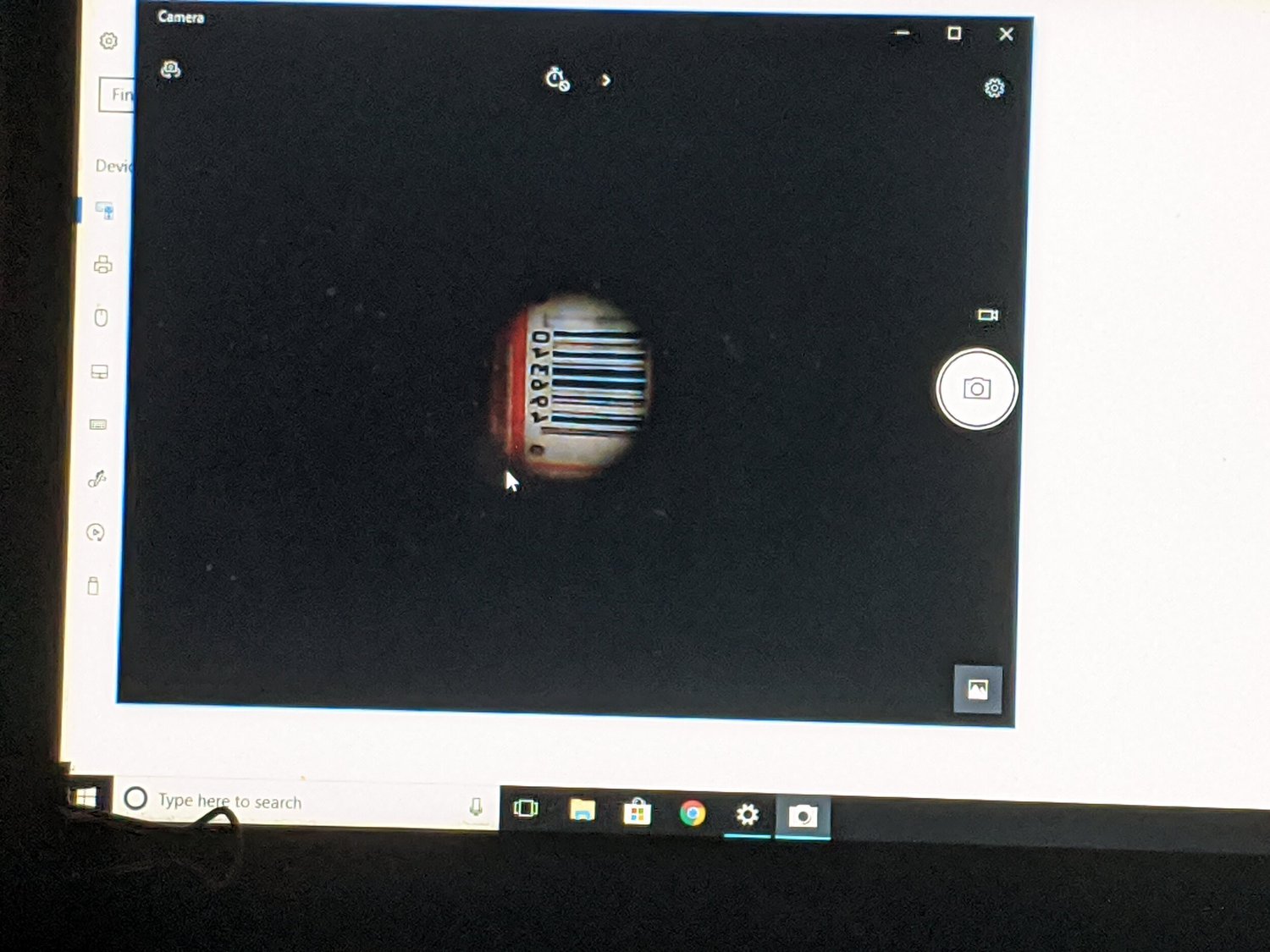
Mirror telescope experimentReading a barcode from about 20 feet awayA camera view of the numbers beside the barcode on a soft-drink can positioned about 20 feet away. I used the small printed details as a practical target while checking the image produced by the setup.
Personal project
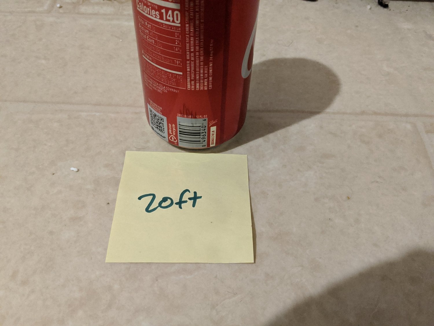
Mirror telescope experimentThe test target at a distanceThe soft-drink can used as the target for the roughly 20-foot imaging test. This photograph provides context for the magnified barcode view captured by the webcam.
Personal project
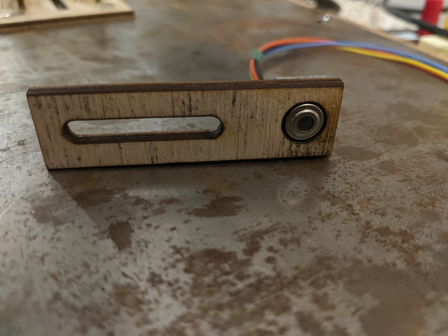
Mirror telescope experimentAn idea for remote temperature measurementAn infrared sensor considered as an attachment to the optical setup. The idea was to estimate the temperature of the spot the instrument was aimed at from a distance. This would have provided a single-point reading; an image would have required an additional scanning system that I had not developed here.
Personal project
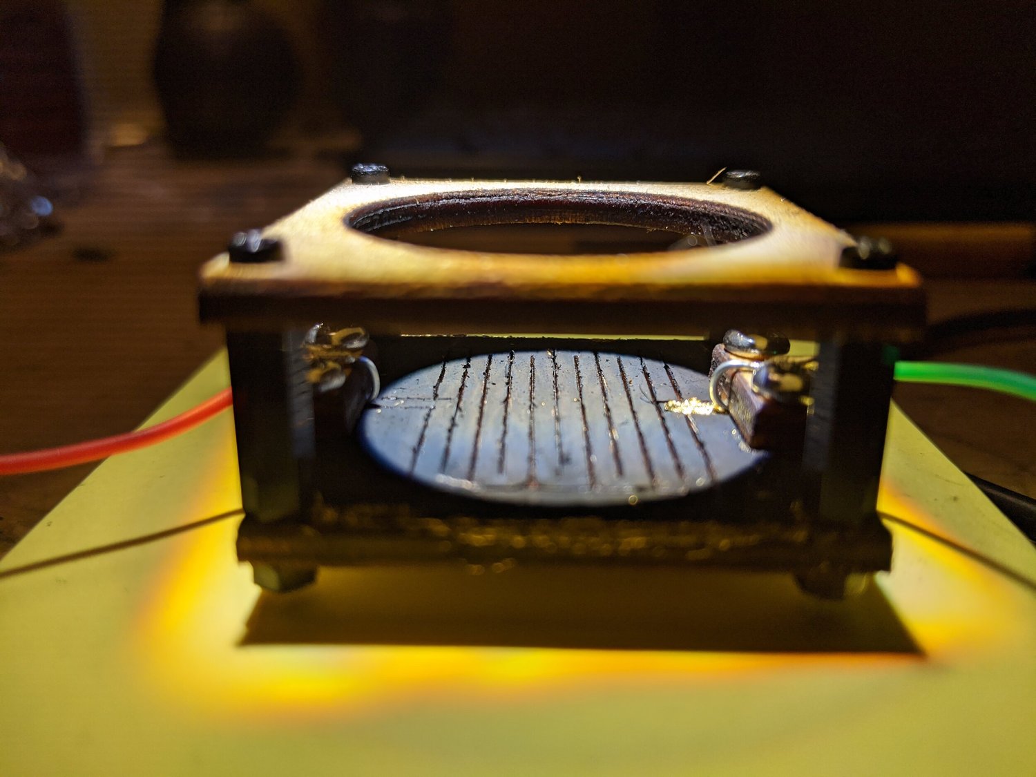
Gold-leaf infrared sensorA gold-leaf bolometer experimentAn attempt to make a bolometer—a sensor that detects heating through a change in electrical resistance. I applied gold leaf to a wooden support, blackened it with soot to absorb light, and used a laser cutter to form a winding conductive pattern. The intended signal was the resistance change as absorbed light warmed the thin gold.
Personal project
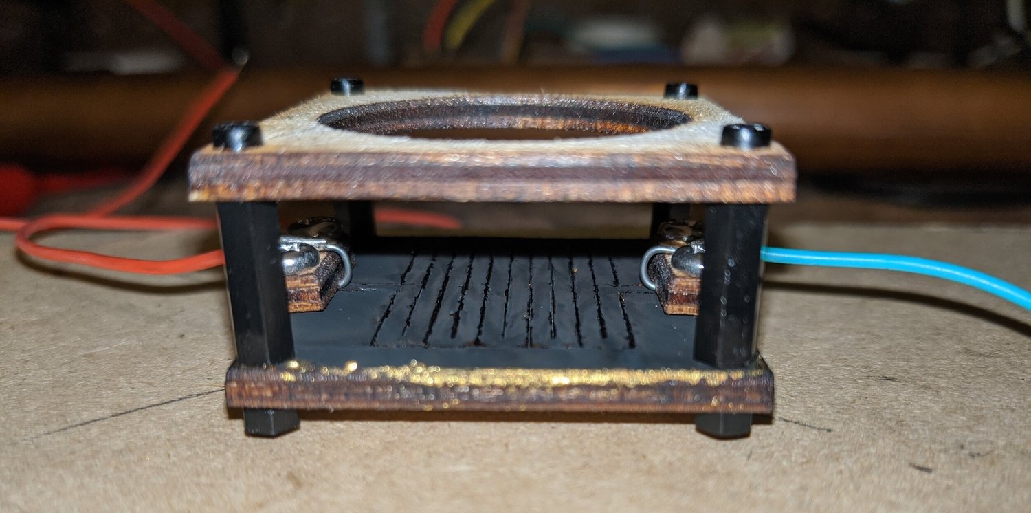
Gold-leaf infrared sensorAnother view of the thin-film sensorAnother angle on the experimental gold-leaf sensor. The blackened surface was intended to absorb incoming radiation, while the patterned gold provided the electrical path whose resistance I wanted to monitor.
Personal project
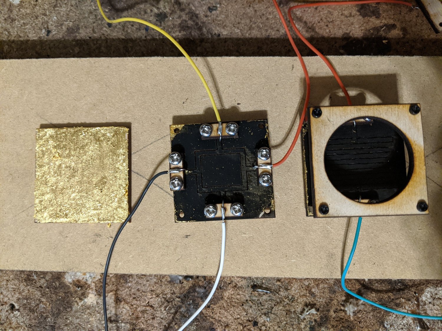
Gold-leaf infrared sensorFrom plain gold leaf to patterned sensorsPlain gold leaf alongside blackened and patterned test pieces. I saw a limited response and thought better thermal isolation from the wooden support might improve it. Suspending the gold leaf above the base was an idea to explore, but its fragility made that difficult. The sensor remained an early experiment.
Personal project
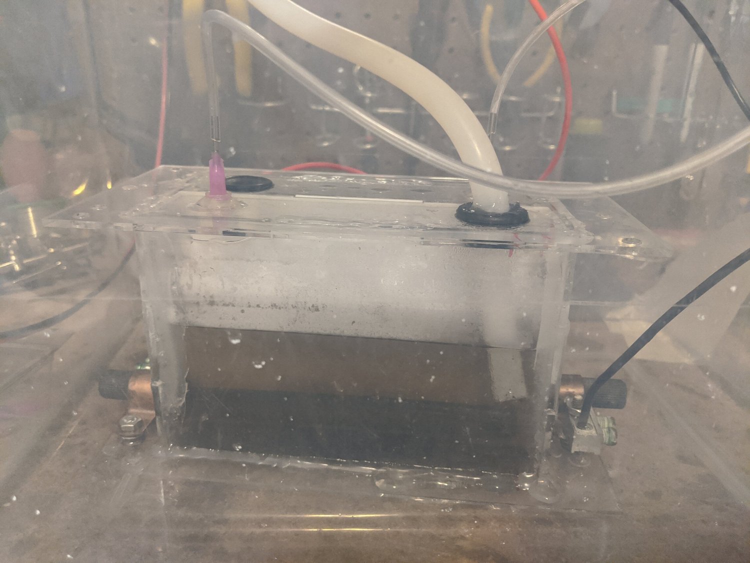
Copper-oxide reduction experimentAn electrolysis cell for a chemistry experimentA water-electrolysis cell I built as part of an experiment in reducing copper oxide to copper metal. The chamber used graphite electrodes and a perforated plastic divider, with gas collected from the two sides. I used the hydrogen in the subsequent reduction experiment; I no longer fully recall the divider’s specific role.
Personal project
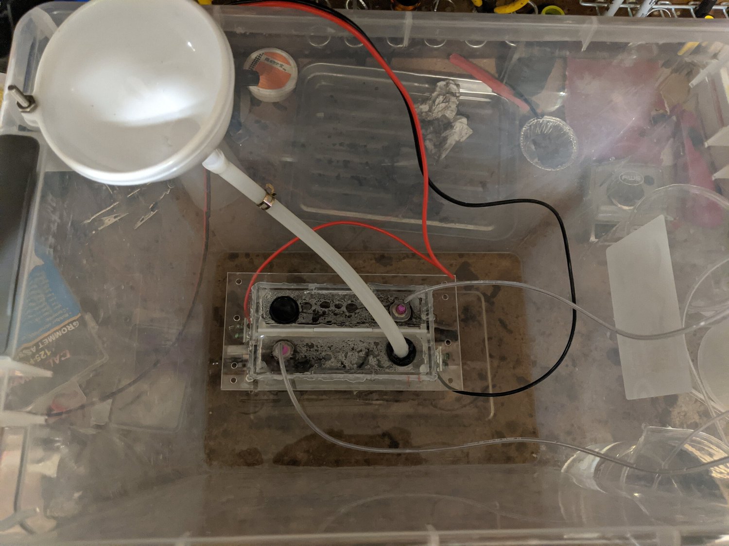
Copper-oxide reduction experimentAnother view of the electrolysis chamberA different angle on the same cell and its gas-collection connections. The project linked water electrolysis with a reduction reaction in which hydrogen removes oxygen from copper oxide, producing copper and water.
Personal project
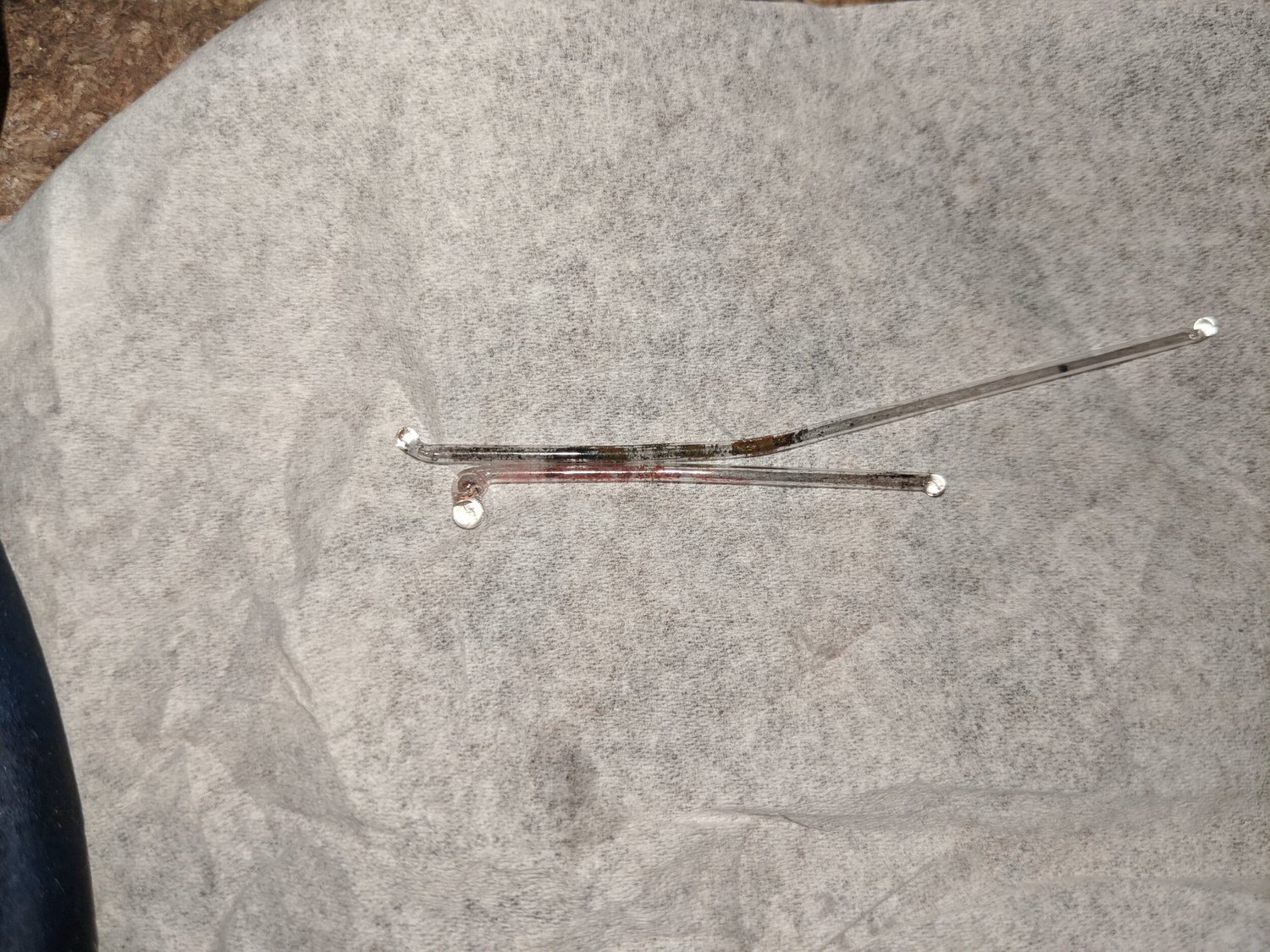
Copper-oxide reduction experimentThe recovered copper and an oxide sampleThe lower glass tube contains the copper recovered from the reduction experiment, while the upper tube holds a small copper-oxide sample for comparison. I sealed the sample tube to limit further oxidation of the recovered metal.
Personal project
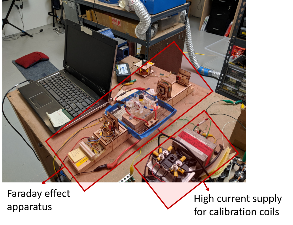
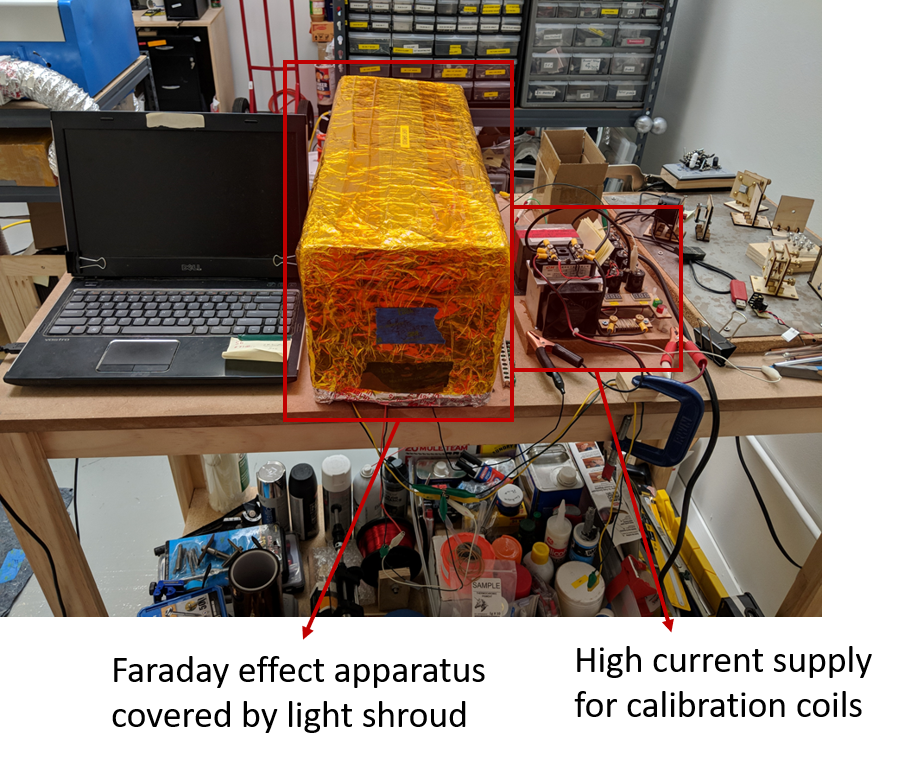
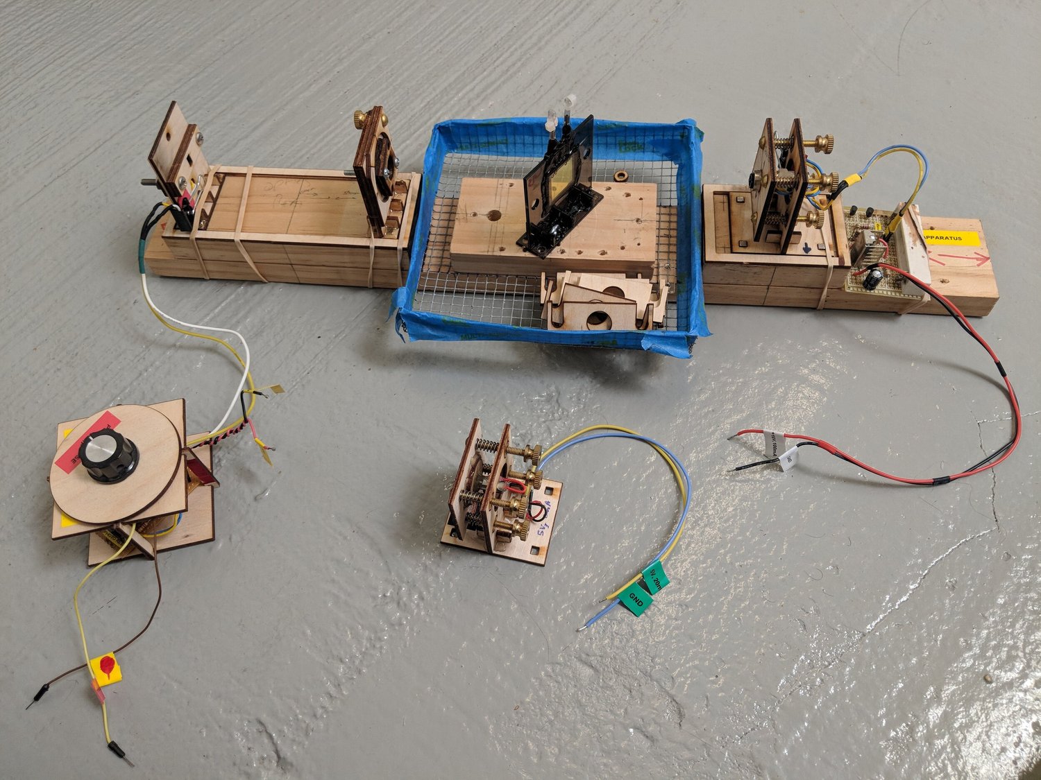
Optical magnetic-field sensorMeasuring magnetic fields with polarized lightAn optical sensing experiment for the magnetic-refrigeration project, using the Faraday effect. A laser passed through virgin olive oil, where an applied magnetic field could rotate the light’s polarization. A second polarizer turned that rotation into a change in brightness for a light sensor to detect. I saw a clear response when testing with the pictured calibration coils, while exploring an approach for strong magnetic pulses.
Personal project
Optical magnetic-field sensorShielding the light sensor from room lightA foil-covered shroud around the optical apparatus helped keep ambient light from reaching the detector. I wanted the recorded signal to reflect changes in the laser light passing through the experiment, with less influence from the surrounding room lighting.
Personal project
Optical magnetic-field sensorThe optical sensing pathFrom right to left: the laser, the olive-oil sample, an adjustable polarizer, and the photoresistor that detected changes in transmitted light. The detector connected to an amplifier so its signal could be recorded. This arrangement let me explore magnetic-field sensing through an optical measurement.
Personal project
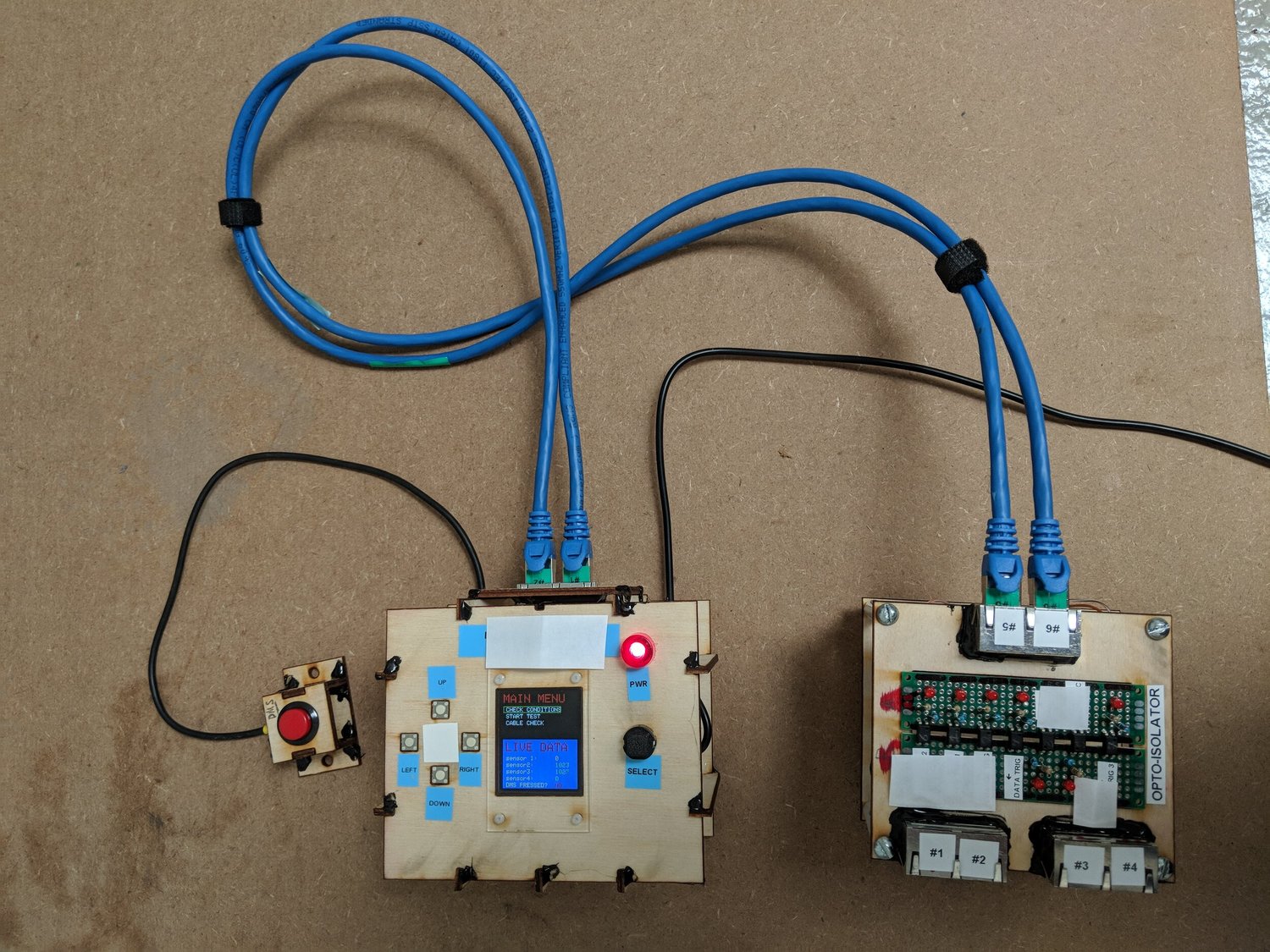
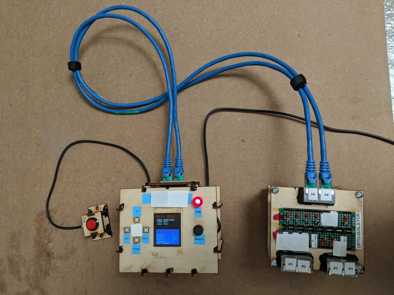
Magnetic-refrigeration experimentsThe magnetic refrigerator’s control interfaceThe small graphical interface used to select experimental programs and display feedback from the magnetic-refrigeration apparatus. Control signals passed through opto-isolators—components that transfer signals using light—to electrically separate the interface from other parts of the system.
Personal project
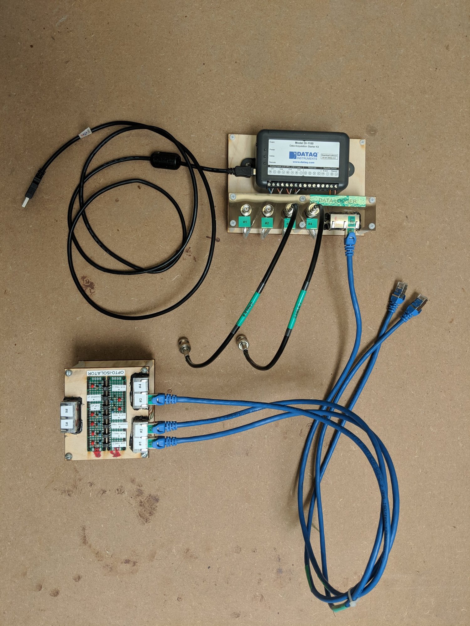
Magnetic-refrigeration experimentsRecording the experimental signalsData loggers used to record signals such as voltage and current during the magnetic-refrigeration experiments. A trigger connection provided a way to start recording at the relevant point in a test.
Personal project
Magnetic-refrigeration experimentsA repeat of the controller photographThis is the same photograph as Photo 165, showing the magnetic-refrigeration control interface and its associated electronics. Both existing photo numbers are retained during the caption review.
Personal project
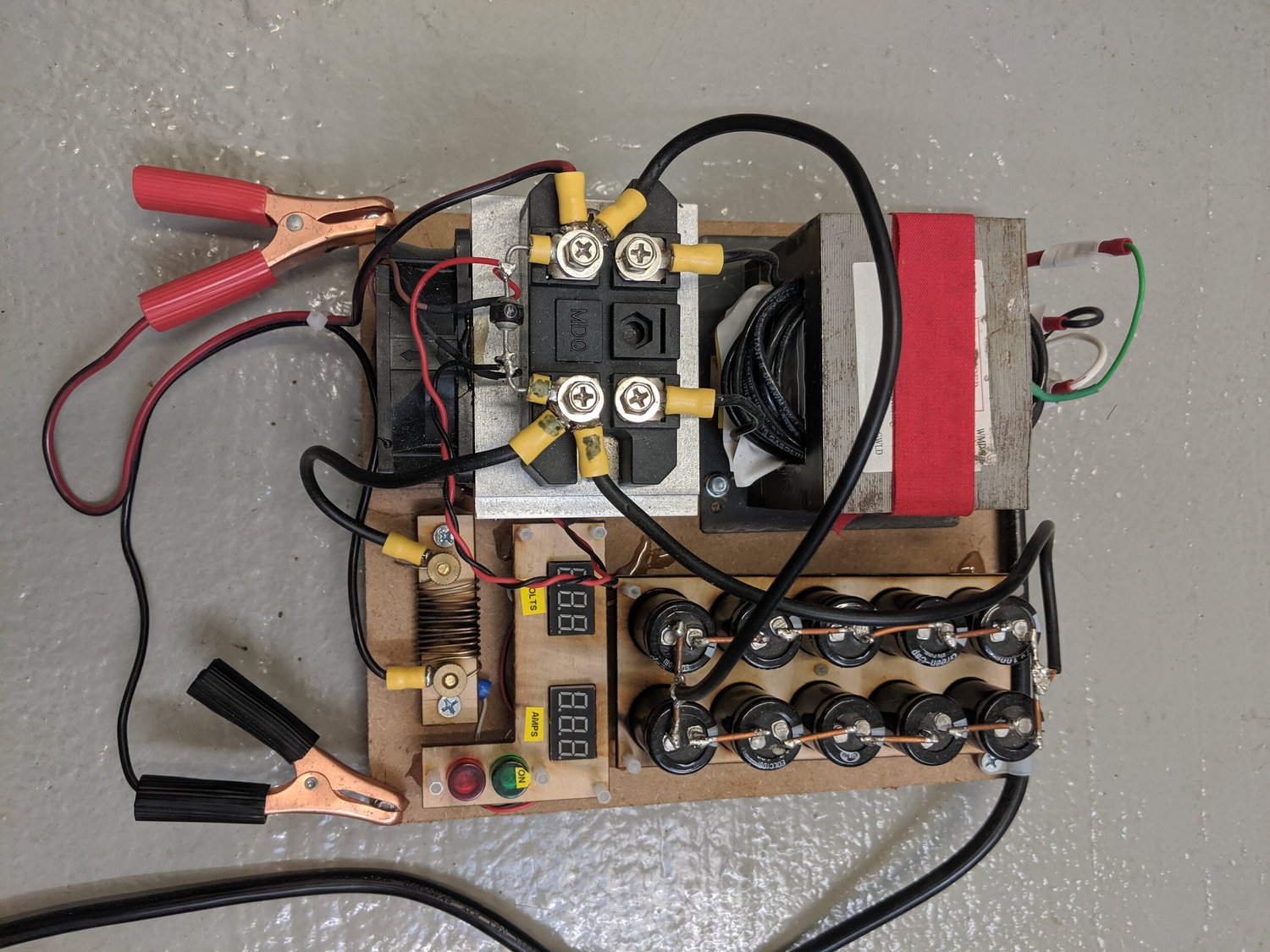
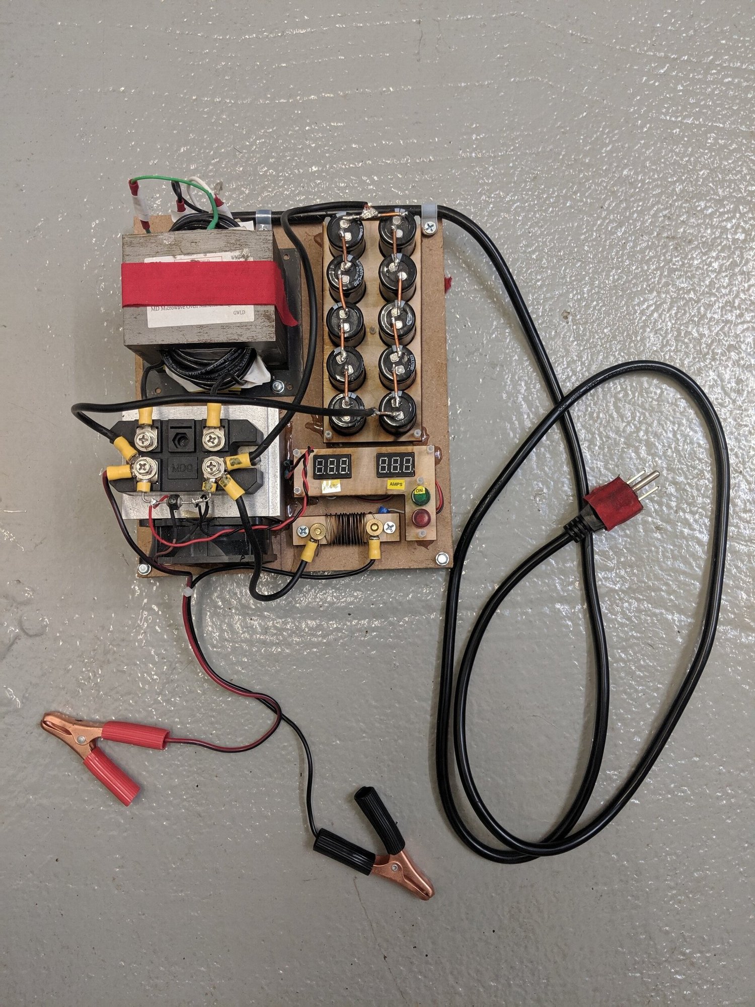
High-current power supplyAn early high-current power supplyAn early high-current supply built around a rewound microwave-oven transformer, with a supercapacitor bank to support brief demands for high current. A rectifier on a heat sink converted the output to DC, and a small panel displayed voltage and current. I used nichrome wire as the current-sensing resistor, but felt it wasted too much power as heat. In a redesign, I would use a lower-resistance sensing element.
Personal project
High-current power supplyAnother view of the high-current supplyA different angle on the same power supply, bringing together the rewound transformer, supercapacitors, rectifier, and monitoring components. This was an early experiment in building a supply capable of delivering high current.
Personal project
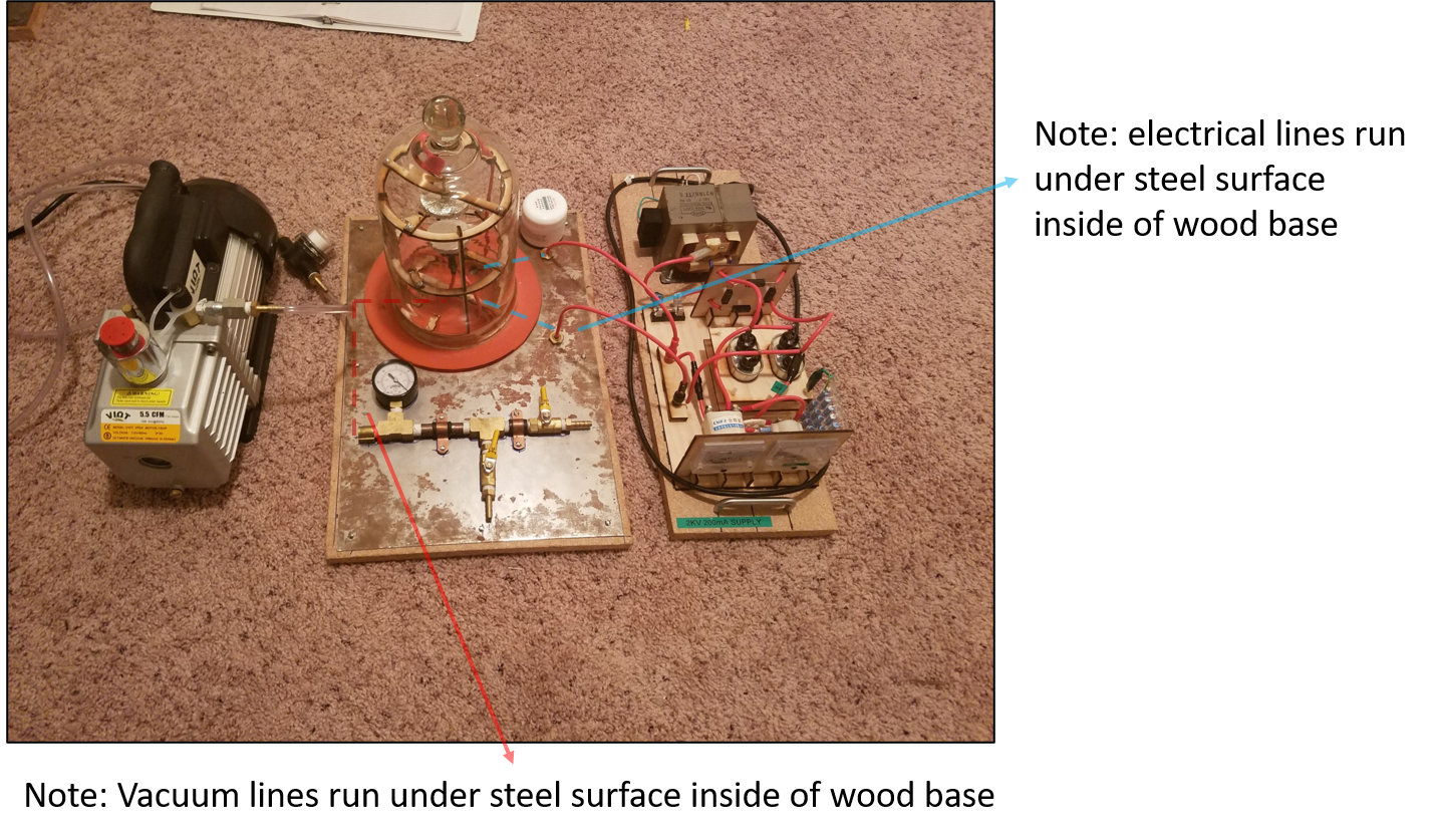
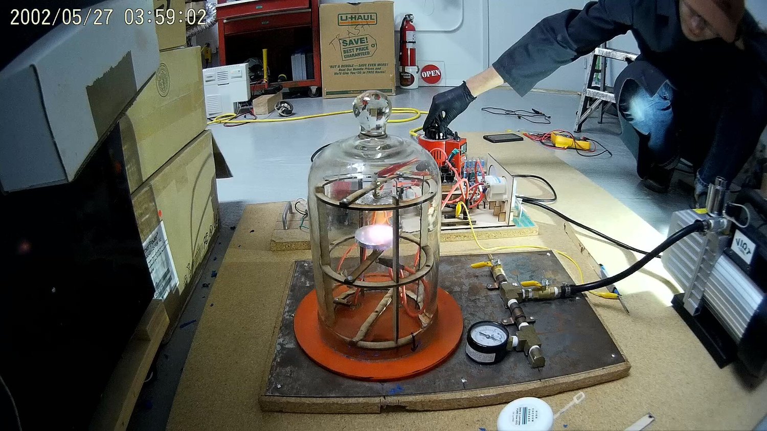
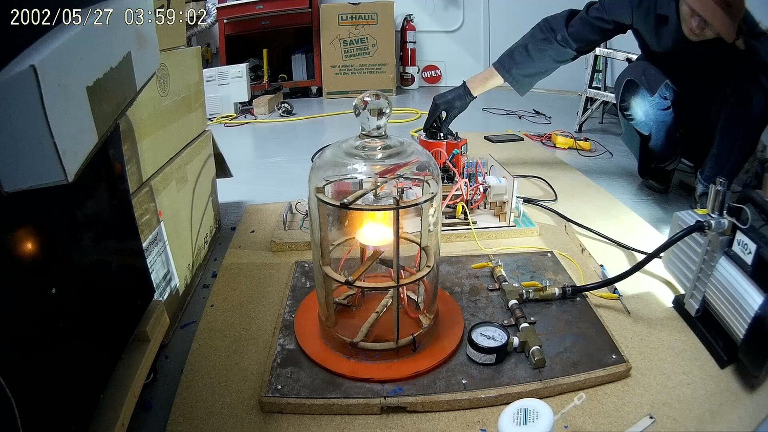
Early plasma vacuum chamberMy first vacuum-chamber experimentsWhat I believe was my first vacuum chamber, used to explore electrical discharges and generate plasma. The vacuum pump sits beside a glass bell jar sealed against a silicone pad, with connections for the pump and electrical feedthroughs. On the right is a transformer-based high-voltage supply with rectification, capacitors, and voltage and current meters. A resistor network scaled the voltage for measurement. At this stage, I was learning to produce plasma rather than using it for a coating process.
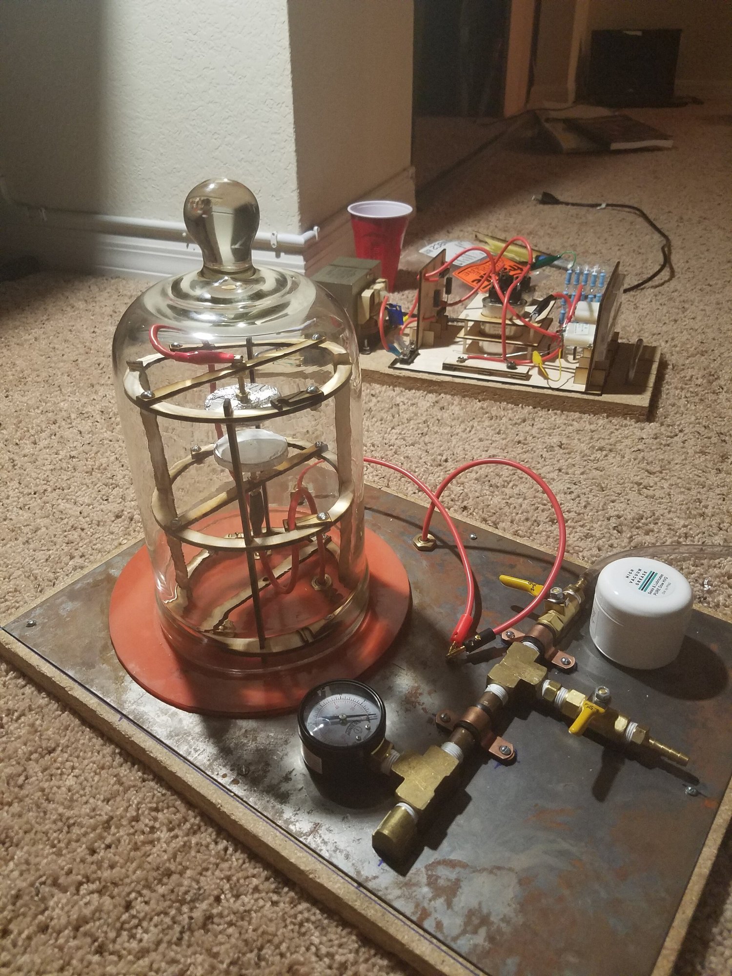
Personal project
Early plasma vacuum chamberAn early electrode support inside the bell jarA wooden scaffold held two electrodes at different heights inside the chamber. I later regarded the wood as a likely source of moisture and other gases released under vacuum. The discharge I produced between the electrodes was strongly orange, and contamination became one of the limitations I wanted to address.
Personal project
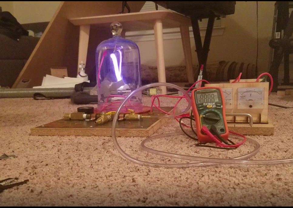
Early plasma vacuum chamberA discharge between wires in the chamberA bright electrical discharge between two wires inside the bell jar. I recall a multimeter failing around this test, although I am not certain of the cause. The photograph also shows the long vinyl-tube connection to the pump, an arrangement I later wanted to reconsider as I learned more about vacuum-system design.
Personal project
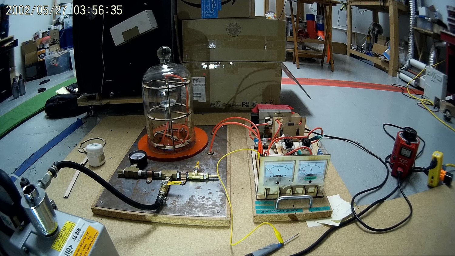
Early plasma vacuum chamberThe chamber connected to its power supplyThe vacuum chamber and high-voltage supply connected for a plasma experiment. This wider view records how the chamber, pump, electrical connections, and measurement equipment were arranged during the early tests.
Personal project
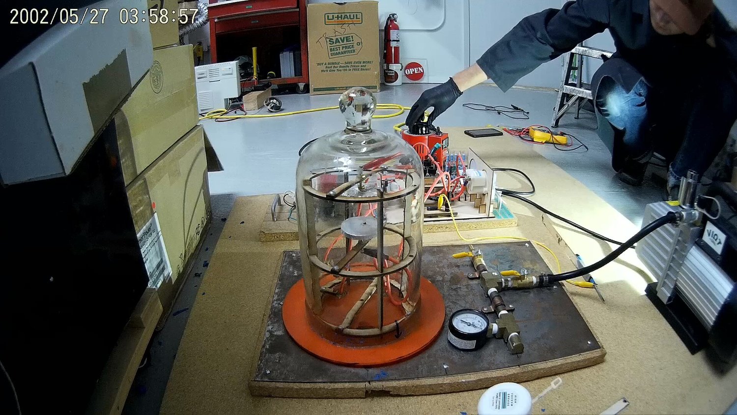
Early plasma vacuum chamberAdjusting the power during a testA view from a test in which I varied the input to the high-voltage supply with a Variac, an adjustable transformer. I was observing how the electrical discharge changed as the experimental conditions changed.
Personal project
Early plasma vacuum chamberPlasma beginning to glow in the bell jarThe visible glow of plasma forming inside the bell jar. These experiments were an introduction to creating and observing electrical discharges in a reduced-pressure environment.
Personal project
Early plasma vacuum chamberAnother view of the plasma experimentAnother view of the glowing discharge inside the bell jar. The images document the early plasma tests and the chamber I used while learning about vacuum equipment, electrode arrangements, and contamination.
Personal project
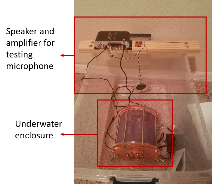
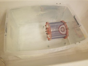
Underwater microphone enclosureA test setup for an underwater microphoneA bin used for experiments with an underwater microphone enclosure. At one end, a speaker was sealed into an acrylic housing with silicone and driven by an audio amplifier. The large clear acrylic cylinder was intended to hold the microphone. The many bolts made access tedious and introduced numerous possible leak paths; for a redesign, I would explore clamping collars around the ends.
Personal project
Underwater microphone enclosure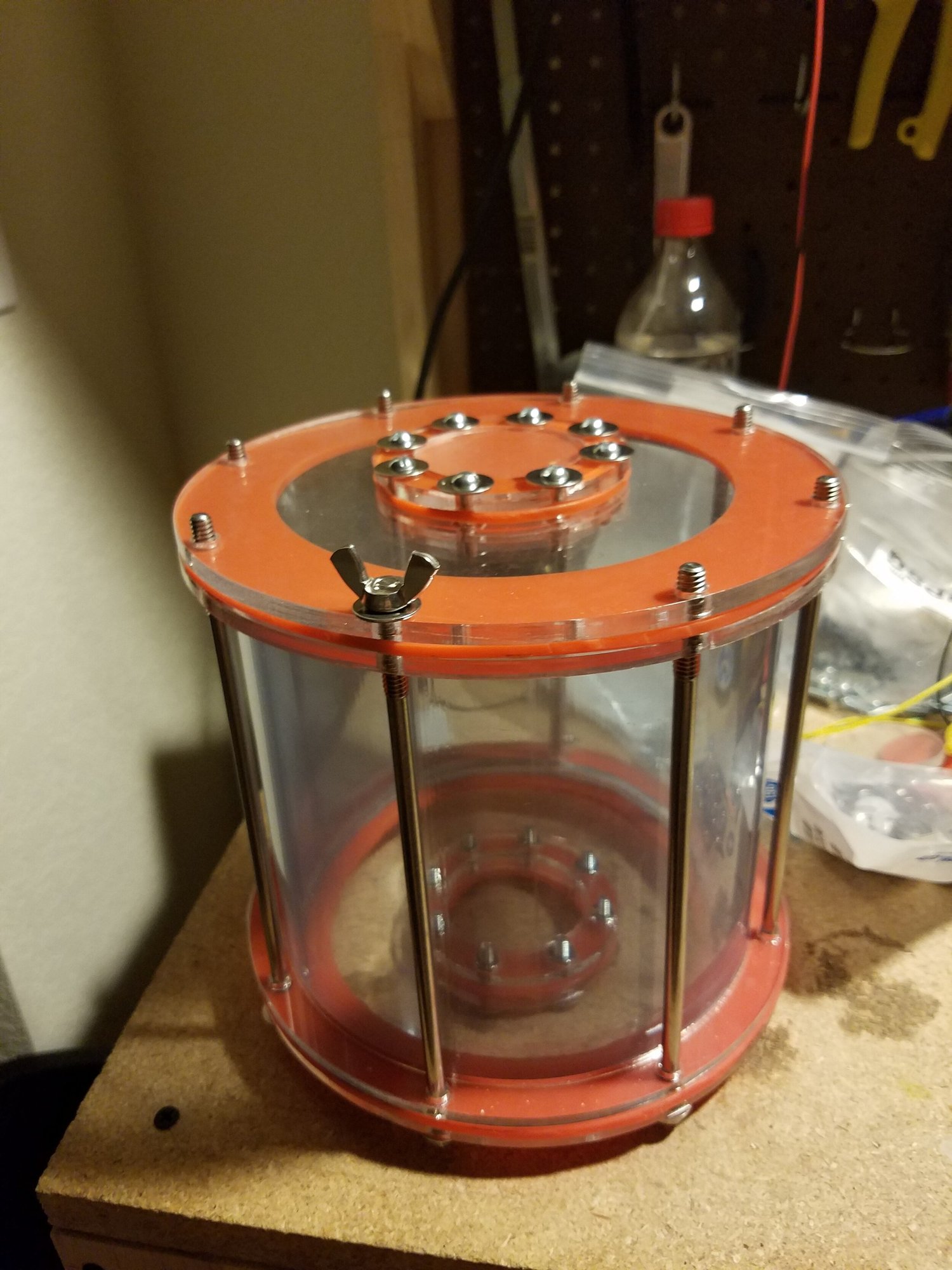
Personal project
Underwater microphone enclosureThe cylindrical microphone enclosureAnother view of the clear acrylic enclosure intended for the underwater microphone. Working with this bolted assembly made me interested in a simpler end-clamping arrangement that would be easier to open and reseal.
Personal project
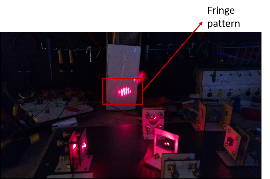
Tabletop Michelson interferometerA tabletop Michelson interferometerA Michelson interferometer assembled with laser-cut mounts for the laser, beam splitter, and two first-surface mirrors. Adjustment screws let me fine-tune the optical alignment. The bright and dark bands on the paper screen are interference fringes, produced when the light traveling along the two paths recombines.
Personal project
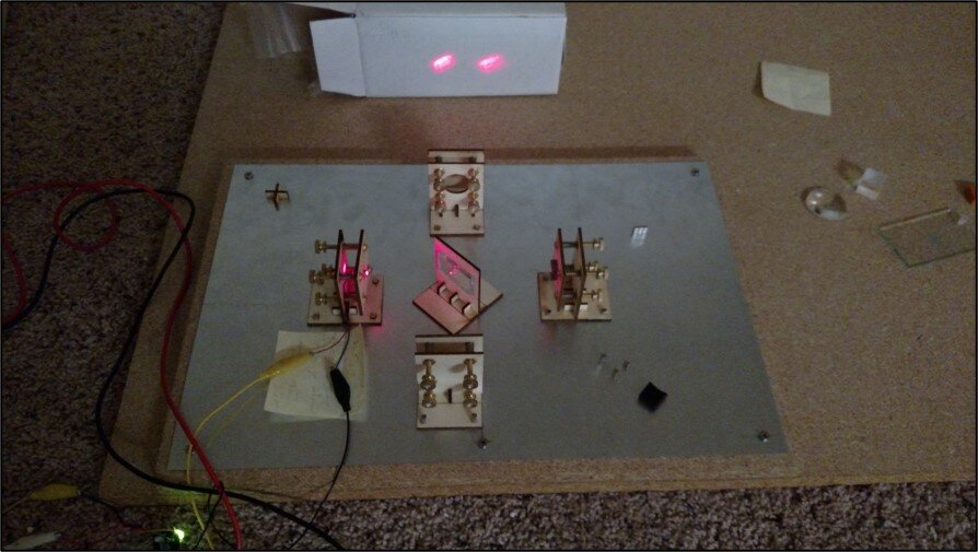
Tabletop Michelson interferometerThe interferometer from another angleAnother view of the tabletop Michelson interferometer and its adjustable optical mounts. Building the holders and aligning the components was a hands-on way to explore how two light paths combine to form an interference pattern.
Personal project
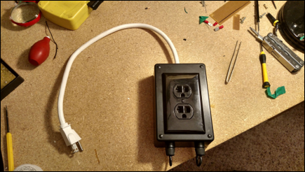
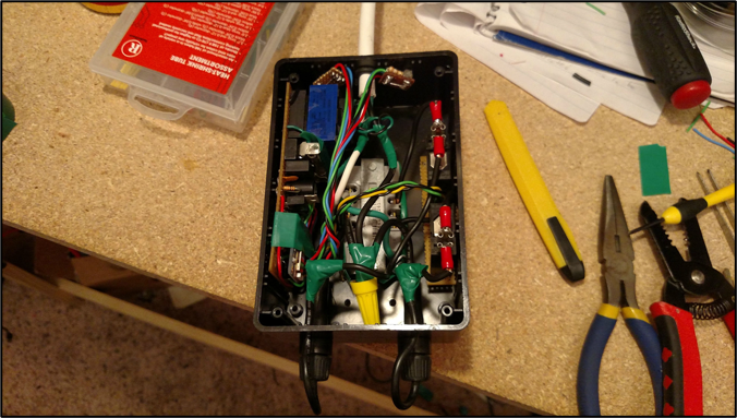
Bluetooth-controlled outletA Bluetooth-controlled outletAn outlet box I built to switch electrical devices through a Bluetooth connection. Inside were a microcontroller, which I recall being an ATmega, a Bluetooth module, a transformer supplying the low-voltage electronics, and two relays that switched the outlets.
Personal project
Bluetooth-controlled outlet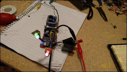
Personal project
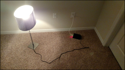
Bluetooth-controlled outletStatus lights on the outlet boxTwo LEDs provided feedback about the outlet controller's state. I used them to indicate whether the outlets were on or off and, as I recall, whether the Bluetooth connection was established.
Personal project
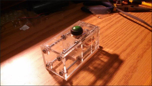
Bluetooth-controlled outletTesting the outlet with a lampThe Bluetooth-controlled outlet powering a lamp during a test. The lamp gave a clear visual indication of the outlet's switching behavior.
Personal project
Laser business cardA business card that projects lightA small laser projector I made to hand out in place of a paper business card. Light passed through an engraved acrylic element to project a pattern containing my name and contact details onto a surface. I recall powering this compact version with coin cells. It was a playful way to introduce my work when making new contacts.
Personal project
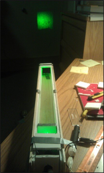
Laser business cardAn earlier laser business-card prototypeAn earlier, larger version of the projecting business card. This prototype used a green laser pointer, before I developed the more compact red-laser version.
Personal project
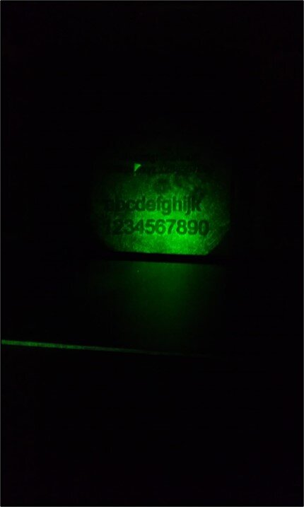
Laser business cardThe projected business-card patternThe pattern projected by the engraved acrylic element. This was the effect behind the laser business card: a small handheld object that could display an introduction on a nearby surface.
Personal project
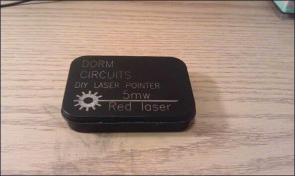
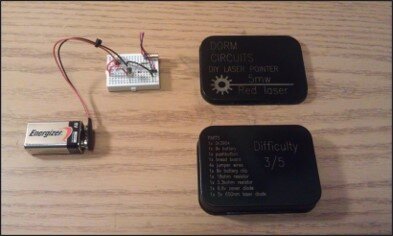
Dorm Circuits laser kitThe engraved case for a laser-pointer kitA red laser-pointer kit I created under the Dorm Circuits name. I used a laser cutter to engrave the lettering and graphics into the matte black case. The crisp markings gave the small kit a finished appearance.
Personal project
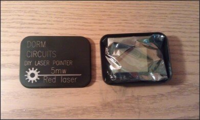
Dorm Circuits laser kitThe kit packaged inside its caseThe opened laser-pointer kit, with the components packaged in an antistatic bag. I liked how the protective packaging complemented the engraved case and made the kit feel like a complete product.
Personal project
Dorm Circuits laser kitThe assembled Dorm Circuits kitThe laser-pointer kit assembled on a miniature breadboard, shown beside a nine-volt battery and its engraved case. The circuit included a voltage regulator and a pushbutton for the laser. I made a small batch under Dorm Circuits LLC—roughly 10 to 20 kits, as I recall—and sold them mostly to family. It was an early experience of turning an electronics project into something other people could assemble.
Personal project
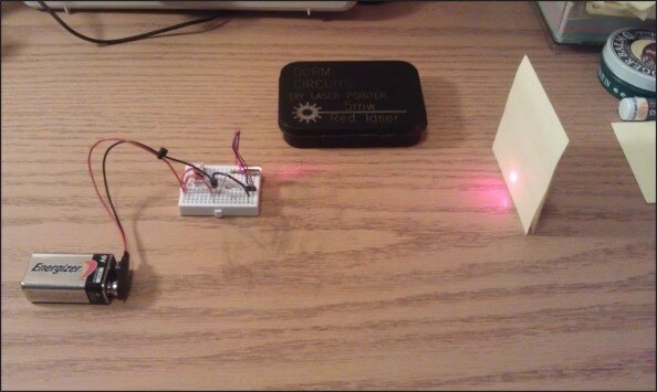
Dorm Circuits laser kitThe assembled laser kit operatingThe completed Dorm Circuits laser-pointer kit switched on. The kit used a red laser module labeled at five milliwatts and brought the components together on a small breadboard.
Personal project
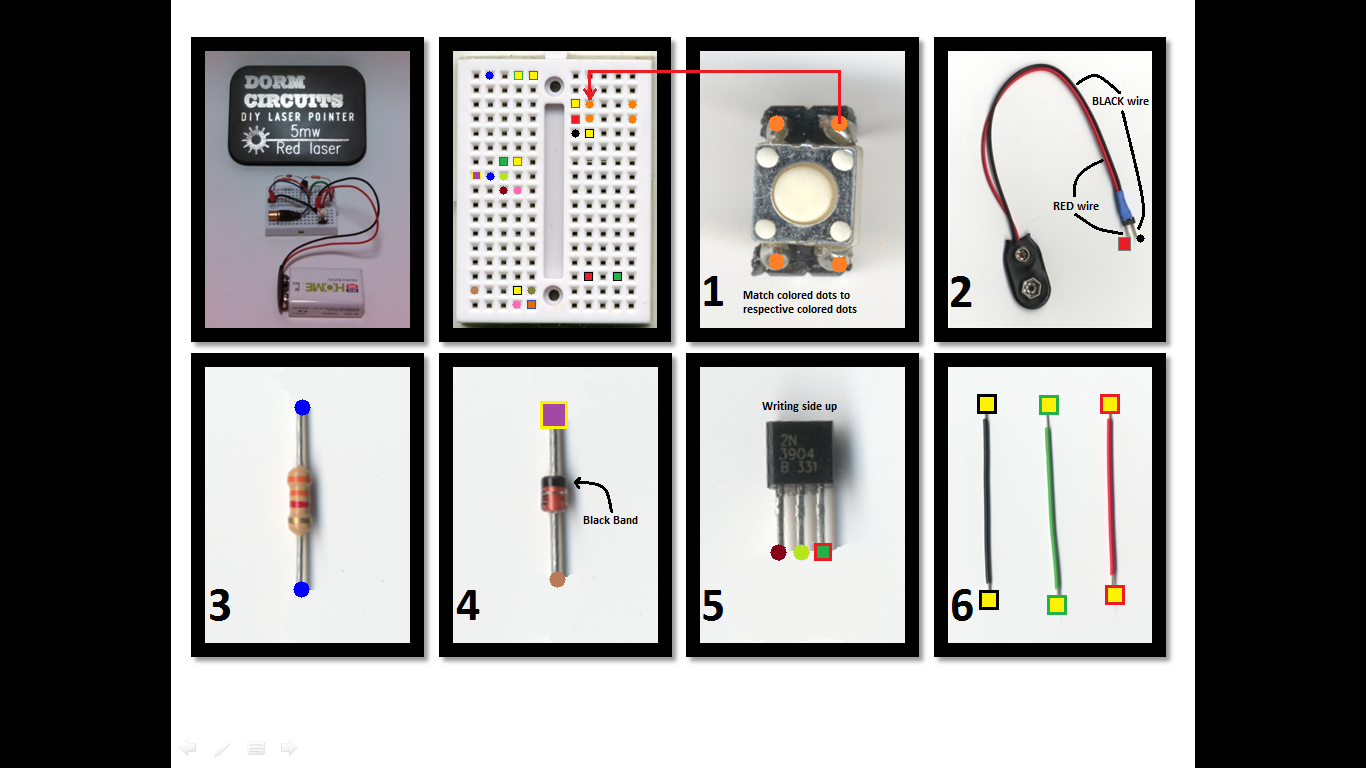
Dorm Circuits laser kitAssembly instructions built around matching dotsThe kit's illustrated assembly guide, showing the components and where they fit on the breadboard. I used matching colored dots to connect each component lead with its intended position. The approach was inspired by IKEA-style visual instructions: I wanted the kit to be as self-explanatory as possible, though I would have liked more feedback from people using it.
Personal project
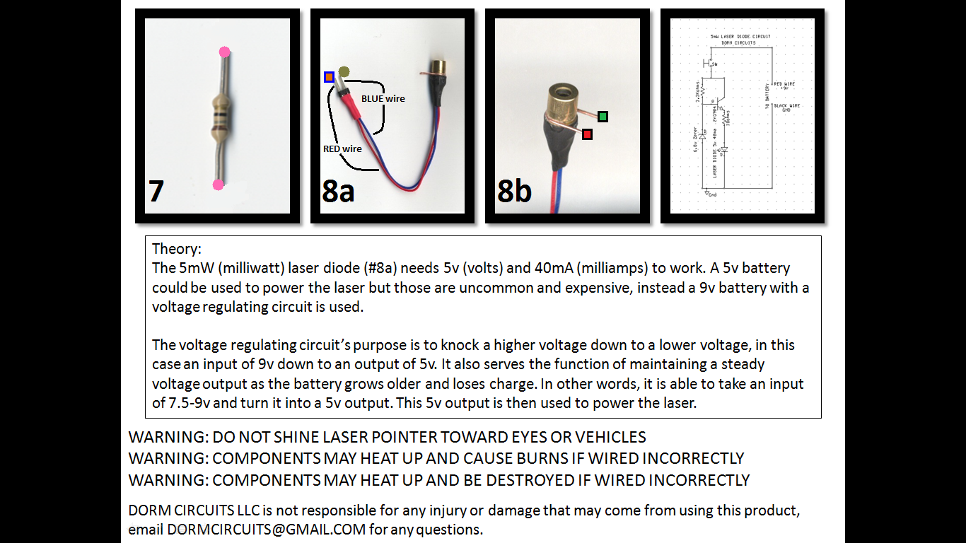
Dorm Circuits laser kitExplaining the circuit behind the kitThe second instruction sheet combines component photographs, a schematic, and an explanation of the voltage-regulating circuit. A Zener diode provides a voltage reference for a transistor that supplies the laser module. I also included handling warnings, including keeping the beam away from eyes and vehicles. The aim was to explain what the assembled circuit was doing as well as how its parts fit together.
Personal project
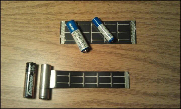
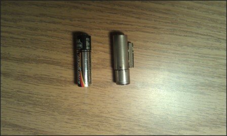
EKO Cell solar battery conceptEKO Cell: a solar-rechargeable battery conceptEKO Cell was a proof of concept I developed for an innovation competition at Lehigh University. It packaged a rechargeable AAA cell and a solar panel inside an AA-size shell, aiming to provide a rechargeable option for AA-powered devices. The smaller cell meant less capacity, with limitations for demanding loads. The project won third place and a $1,000 award—an encouraging early experience of pitching an idea.
Personal project
EKO Cell solar battery concept
Personal project
EKO Cell solar battery conceptThe EKO Cell logoThe logo I designed for EKO Cell. Turned on its side, the E, K, and O suggest the ground, a plant, and the sun. I wanted the lettering itself to reflect the solar-powered idea behind the battery concept.
Personal project
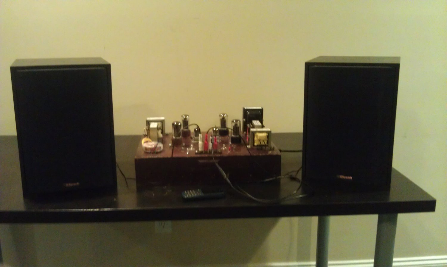
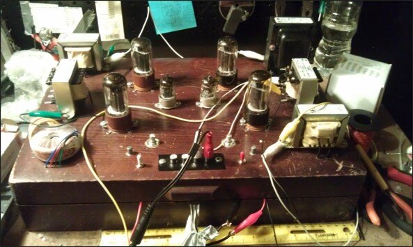
Vacuum-tube stereo amplifierA tube amplifier in my grandfather's wooden caseAn early vacuum-tube stereo amplifier built into a wooden case my grandfather had made for a seashell collection. I repurposed it to hold the tubes, transformers, and other components. Inside, the circuitry was connected point to point with a tangle of wiring. Many of the parts came from a warehouse full of old electronics that I visited on a trip to New York with my brother.
Personal project
Vacuum-tube stereo amplifier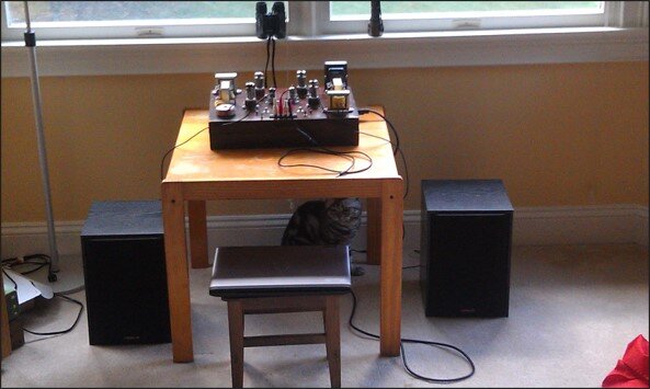
Personal project
Vacuum-tube stereo amplifierThe complete stereo setup, with ZeldaThe finished tube amplifier with a speaker on either side. Its RCA inputs let me connect a phone or laptop using an audio adapter cable to play music. Under the table is Zelda, our much-loved family cat, who has since passed away—an especially meaningful detail in this photograph.
Contract work
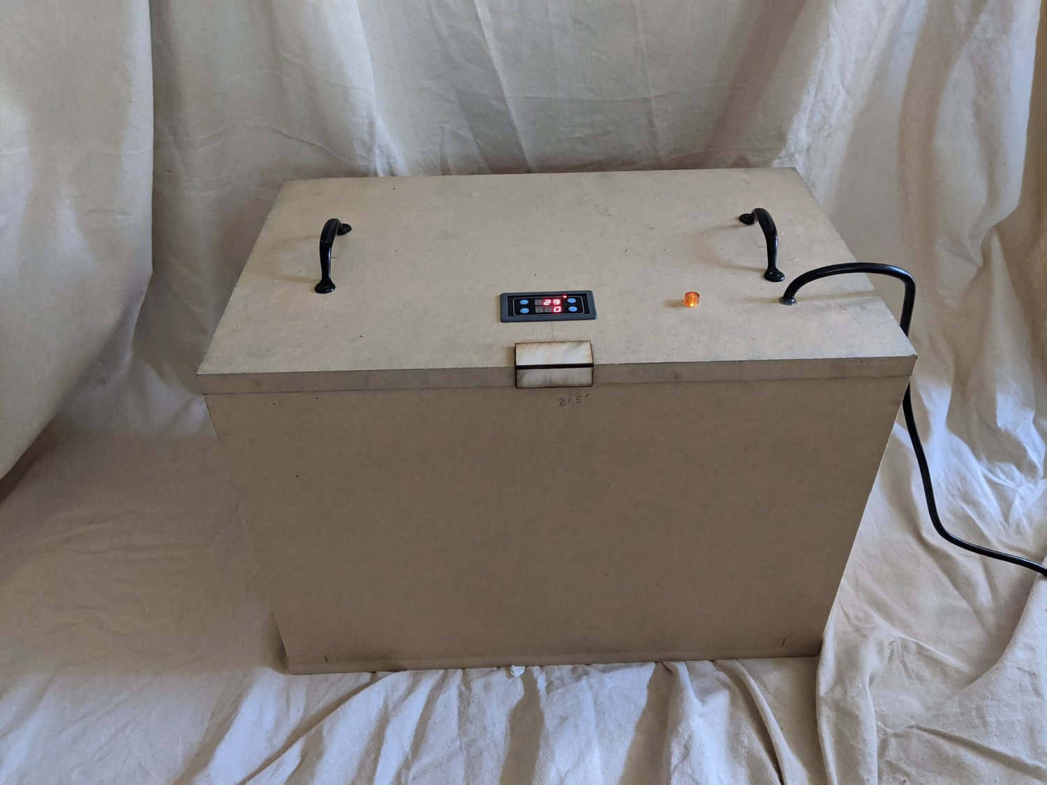
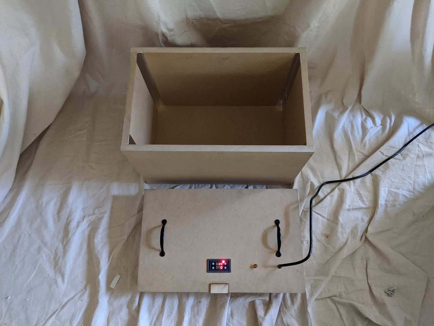
Adjustable light-test enclosureAn adjustable enclosure for disinfection researchA test enclosure I built for a physician client during 2020. It was intended for studying how light-source distance and exposure time affected disinfection: internal pegs supported a platform at different heights, and a timer controlled how long the lamps stayed on. The photographs show ordinary fluorescent lamps fitted for demonstration, rather than UVC lamps.
Contract work
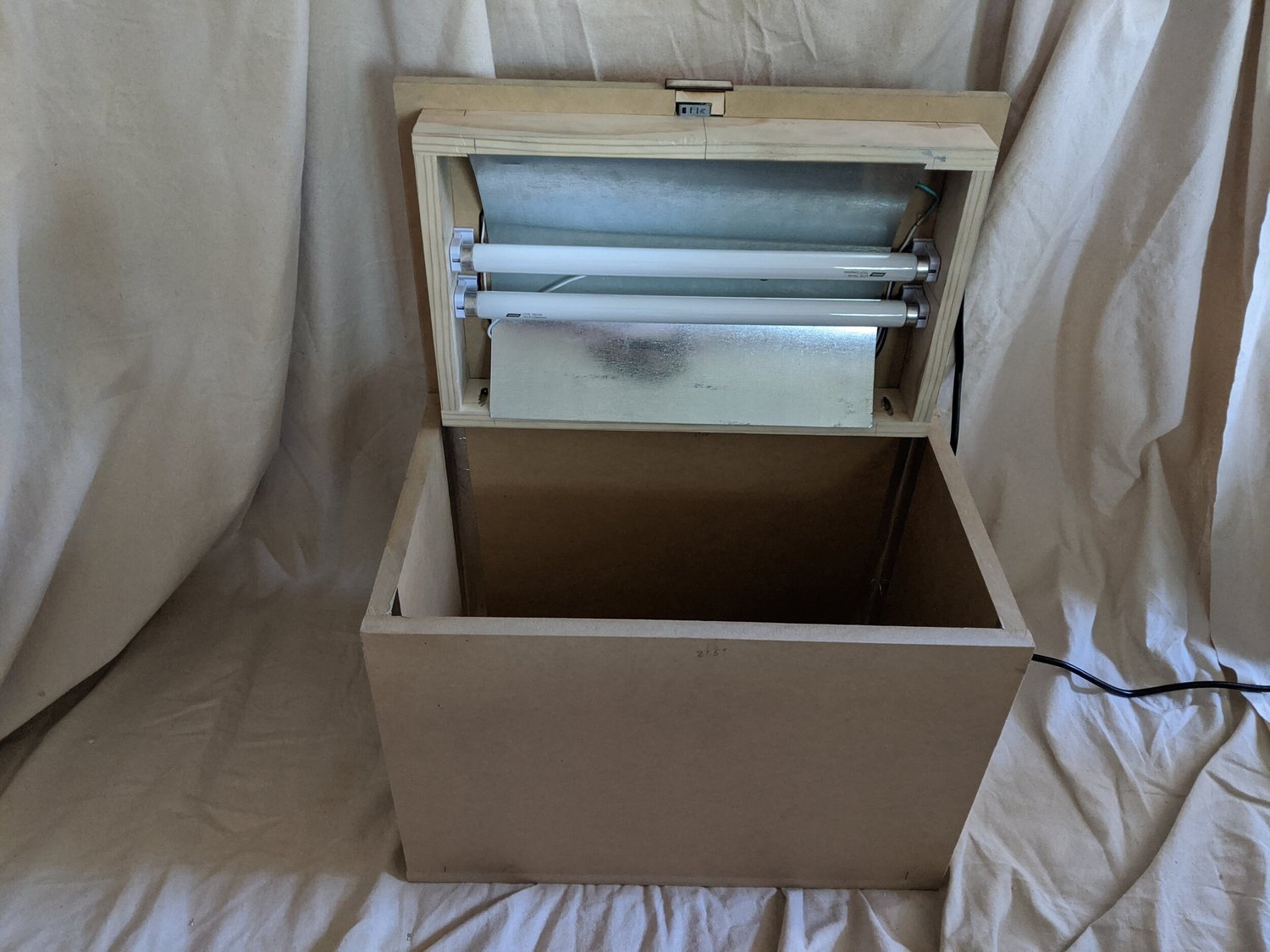
Adjustable light-test enclosureInside the adjustable test enclosureThe enclosure opened to show the interior and its adjustable platform supports. The different support positions let the client change the sample's distance from the light source for experimental comparisons.
Contract work
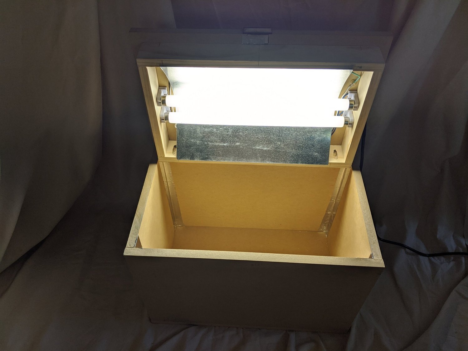
Adjustable light-test enclosureThe enclosure with its demonstration lampsThe open enclosure with its lamps illuminated. These are fluorescent demonstration lamps, showing the physical arrangement of the light sources and test space. The box was built as an experimental fixture for the client's disinfection research.
Contract work
Adjustable light-test enclosureA removable lid and lamp assemblyThe lamp assembly lifted away from the enclosure. I made the box and the lid-mounted lights as two separable parts, allowing access to the test space and the lighting hardware.
Contract work
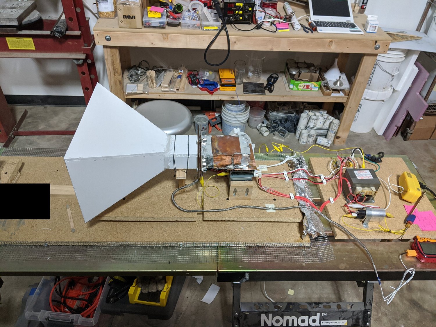
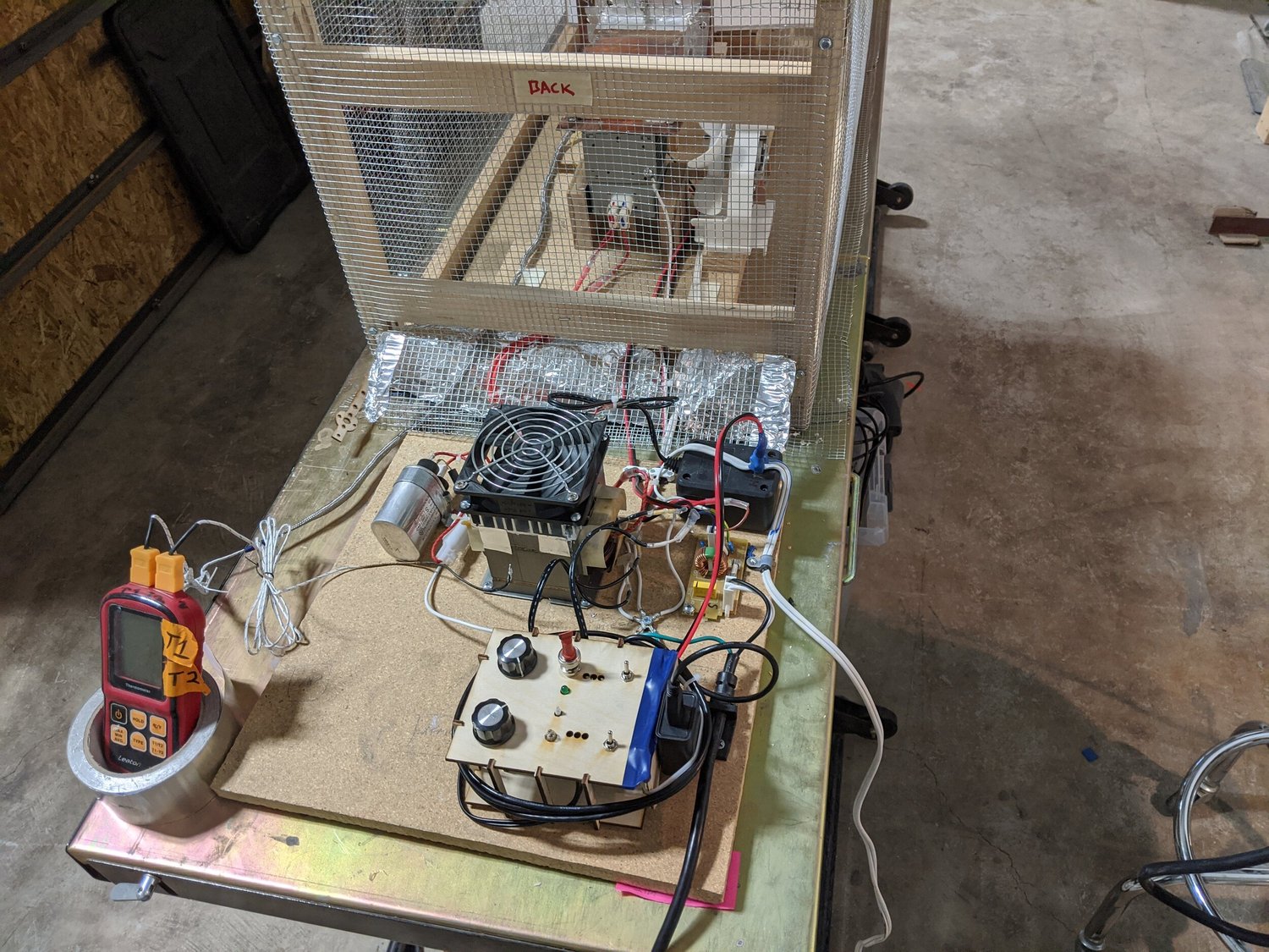
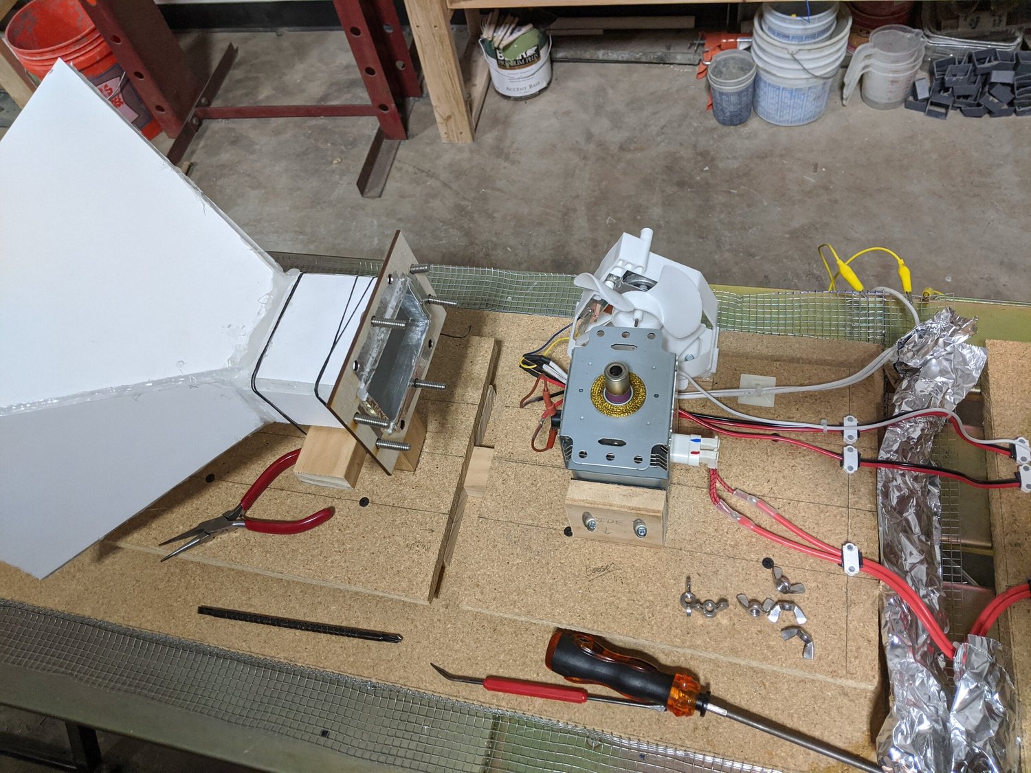
Microwave concrete-curing experimentsExploring faster setting for printed concreteA microwave emitter I built for Three Space Makers, a company exploring concrete 3D printing for houses. The trials investigated whether heating could speed up the material's setting. I recall much shorter setting times, but the rapidly heated samples were also much weaker, making the balance between speed and strength central to the work. One idea was to use the faster-setting material for temporary printing supports. The project ended when the company ran out of funding.
Contract work
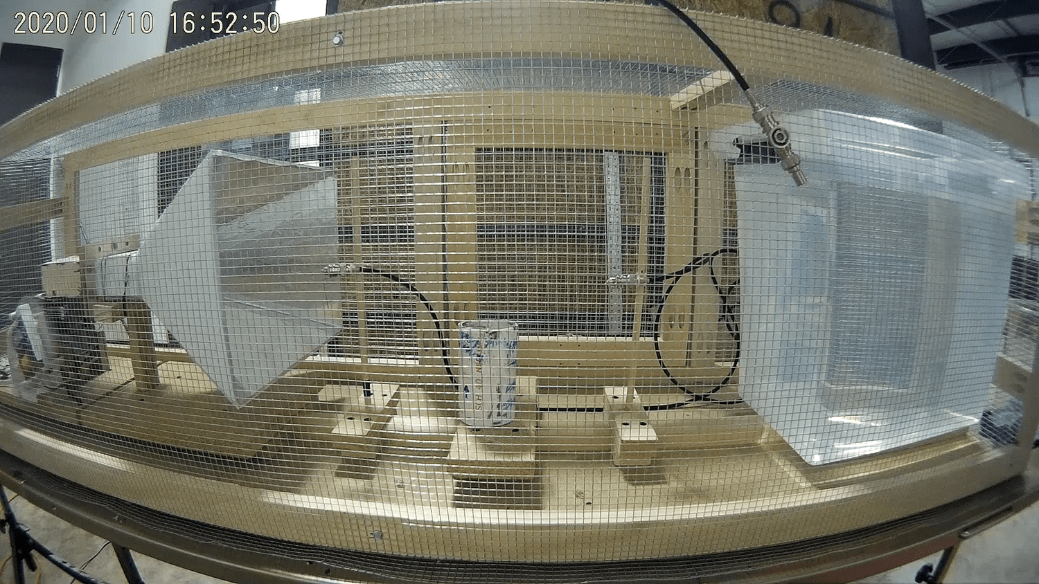
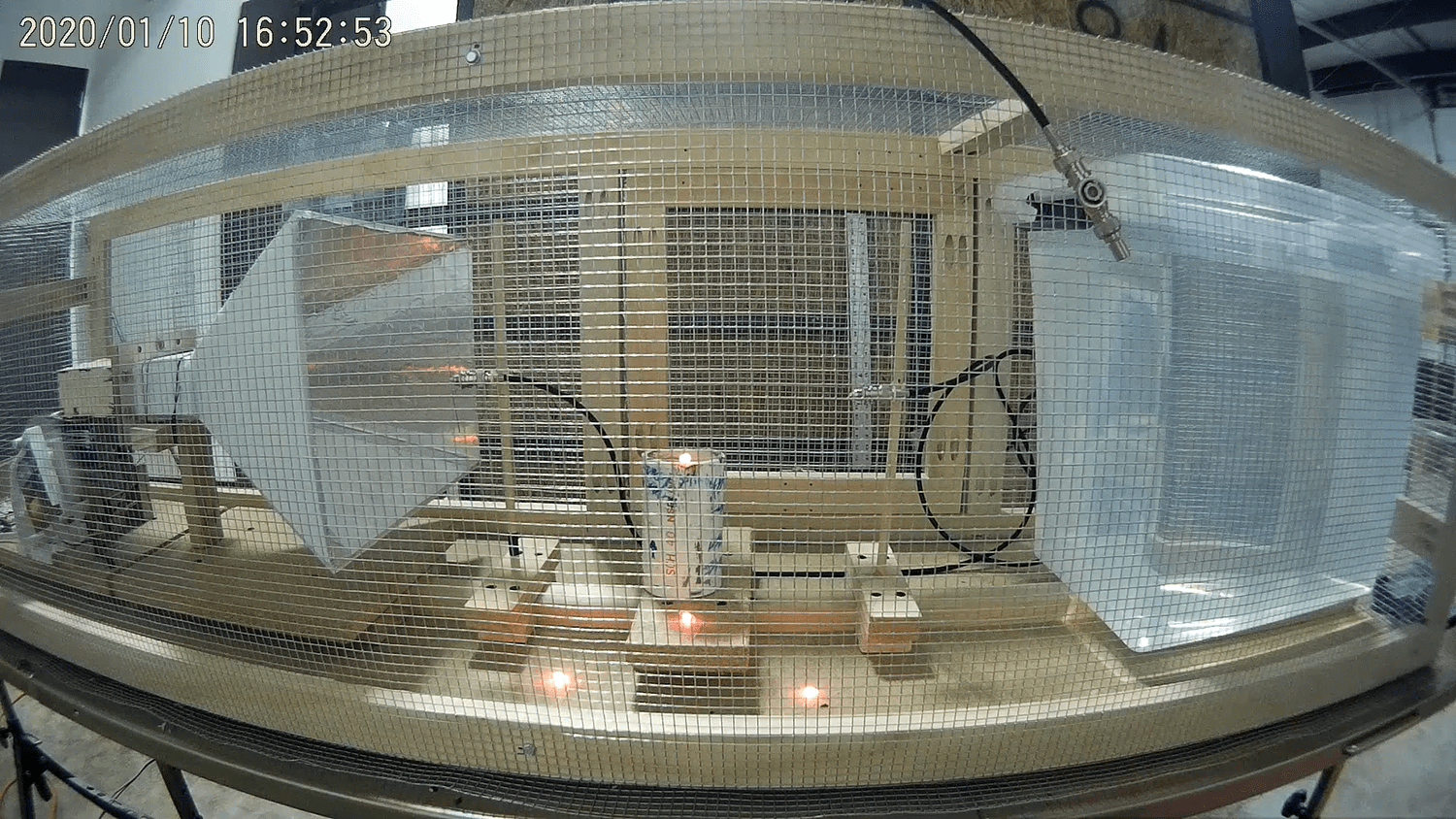
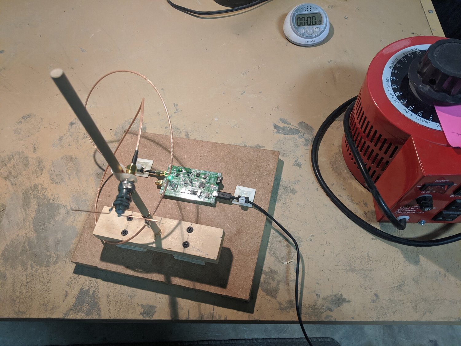
Microwave concrete-curing experimentsThe microwave test enclosure and sample fixtureA metal-mesh enclosure intended to contain microwave energy during the concrete-heating tests. An adjustable fixture changed the sample's distance from the microwave horn. The water container was intended to absorb energy and reduce reflections back toward the emitter. An antenna connected to radio-frequency measurement equipment monitored the received signal in the enclosure.
Contract work
Microwave concrete-curing experimentsNeon lamps glowing without connected wiresNeon lamps placed inside the test enclosure glow during microwave operation, even though no power wires are connected to them. I used them as a striking visual indication that energy was present in the chamber, alongside the electronic measurements used for the project.
Contract work
Microwave concrete-curing experimentsA controller for timed and pulsed testsThe control box for the microwave experiment. It set the duration of operation and could also run a pulsed sequence, giving me a way to control the timing of the heating tests.
Contract work
Microwave concrete-curing experimentsMonitoring the microwave signalThe antenna and radio-frequency measurement hardware used during the tests. This setup let me examine the received signal and its frequency content while developing the microwave-heating apparatus.
Contract work
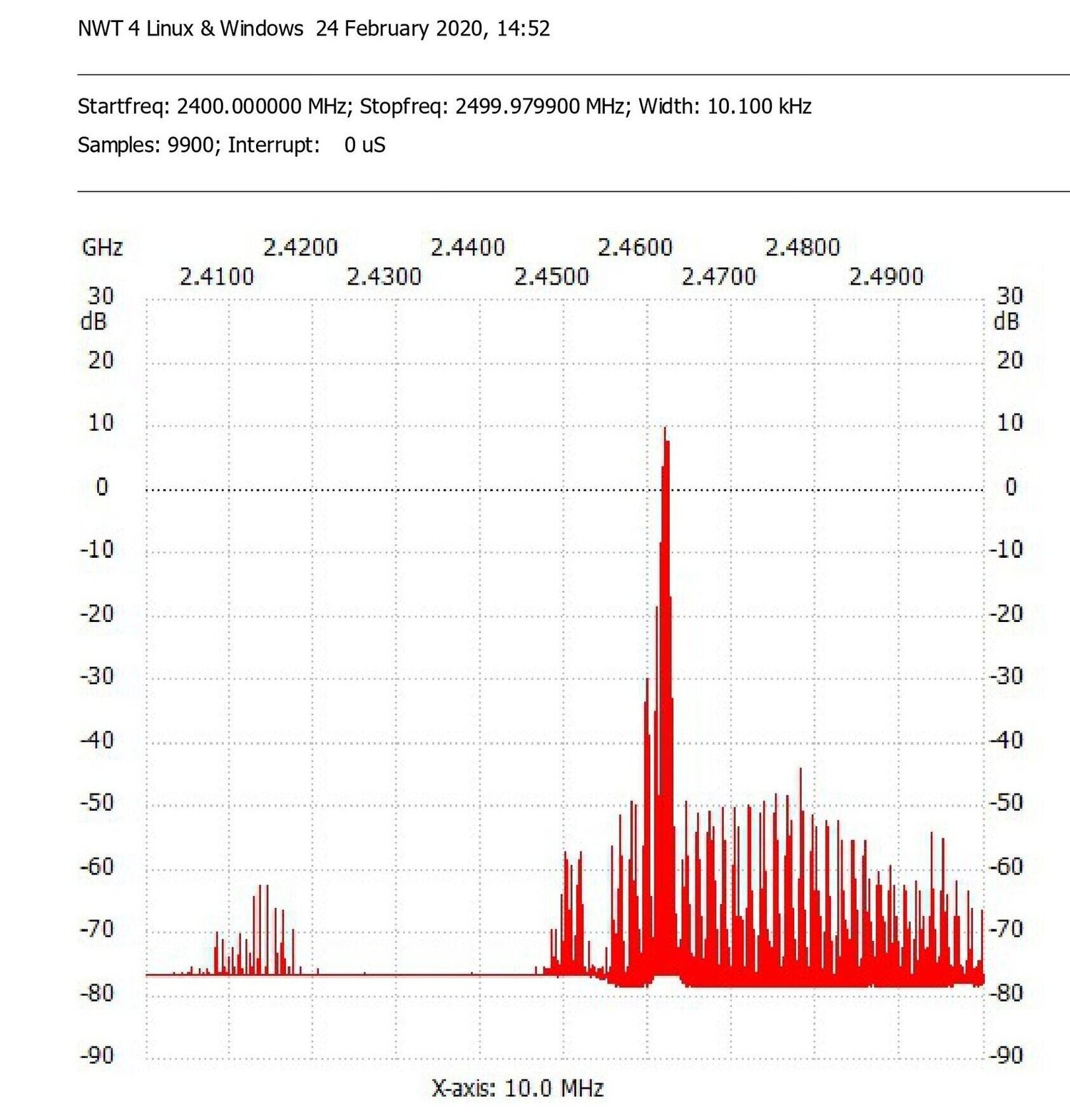
Microwave concrete-curing experimentsThe measured frequency spectrumA frequency plot recorded during the microwave tests. The strongest peak is just above 2.46 GHz within the displayed 2.4–2.5 GHz range. The horizontal axis shows frequency, while the vertical axis shows the instrument's signal level in decibels, making the dominant emission stand out from the surrounding readings.
Contract work
Microwave concrete-curing experimentsThe emitter with its copper launcher removedA view of the emitter head with the copper launcher removed. The project used a source repurposed from a kitchen microwave oven, with a custom launcher and horn that I made with help. This photograph documents the hardware behind the experimental heating setup.
Contract work
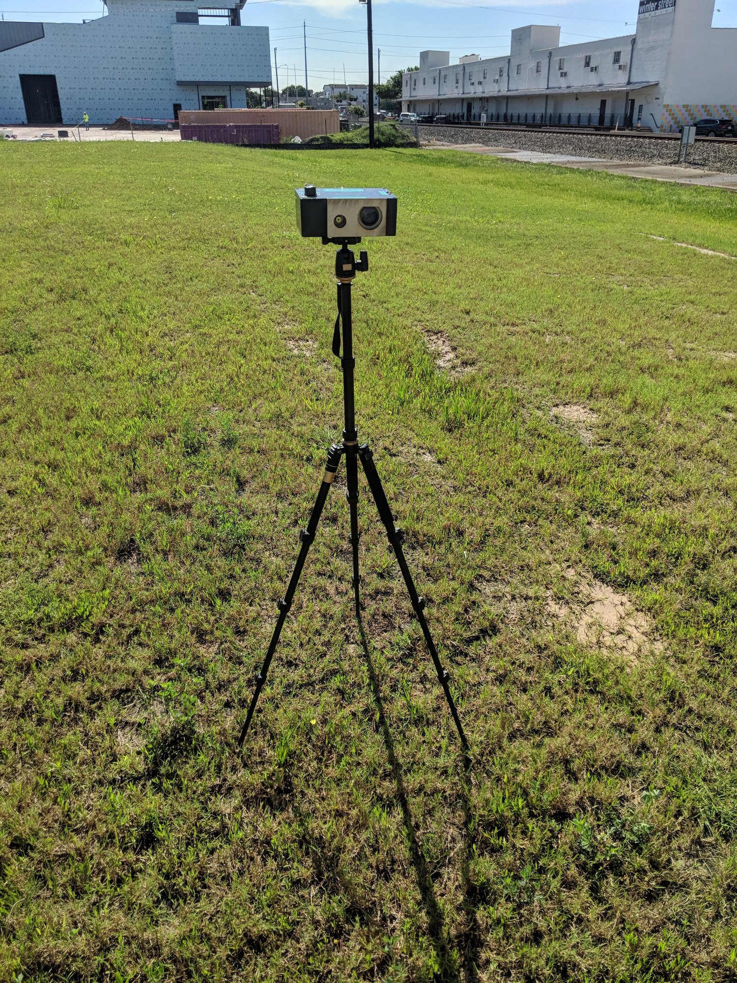
Optical balk-alert prototypeAn optical alert system for a baseball umpireA tripod-mounted prototype I built for a freelance client who wanted to help umpires notice possible balks. The concept used a laser beam as a tripwire: a player crossing the monitored line would interrupt the returning light and trigger a wireless alert. It was intended to draw the umpire's attention to a movement that could be difficult to see from a distance.
Contract work
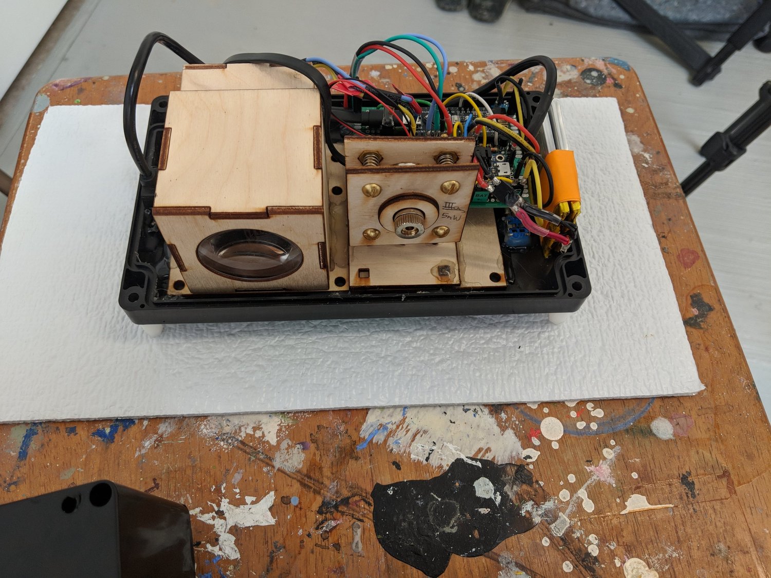
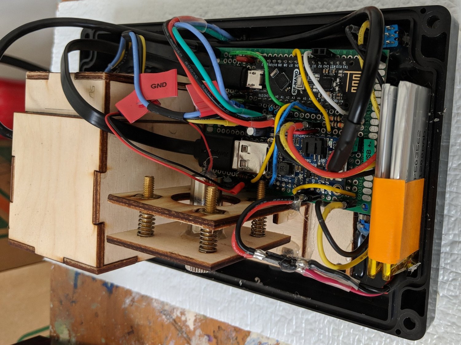
Optical balk-alert prototypeThe laser, receiver optics, and control electronicsInside the detector, the lens on the left collected returning light onto a light sensor, while the red laser on the right sent out the beam. I pulsed the laser so the receiver electronics could distinguish its pattern from background sunlight. A microcontroller handled detection and radio communication, with battery-charging electronics and sensitivity adjustments included in the assembly.
Contract work
Optical balk-alert prototype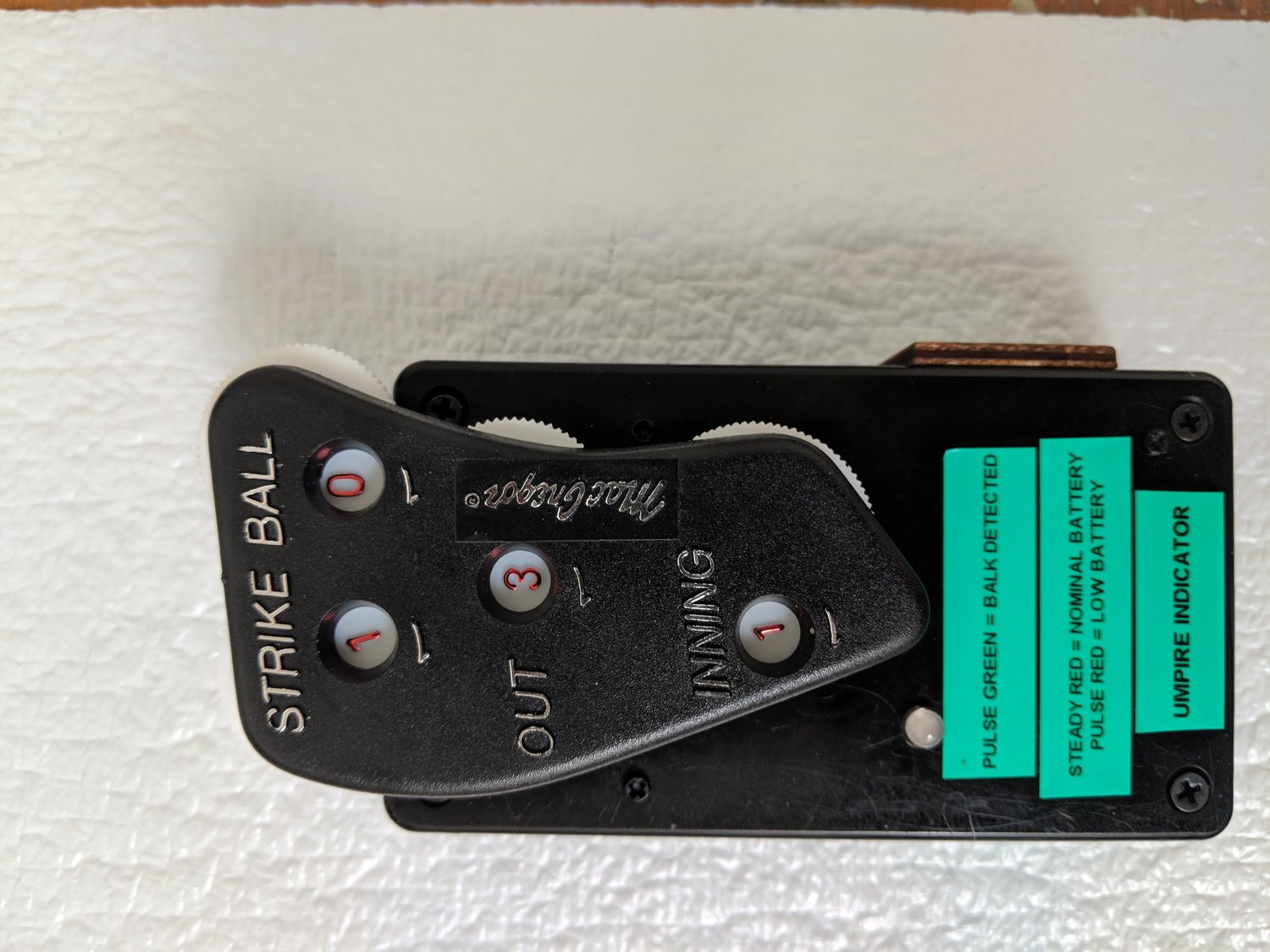
Contract work
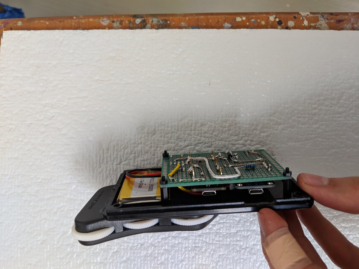
Optical balk-alert prototypeA pocket receiver for the umpireThe handheld receiver intended to be carried in the umpire's pocket. It received an alert from the tripod unit when the monitored beam was interrupted, keeping the notification close to the person making the call.
Contract work
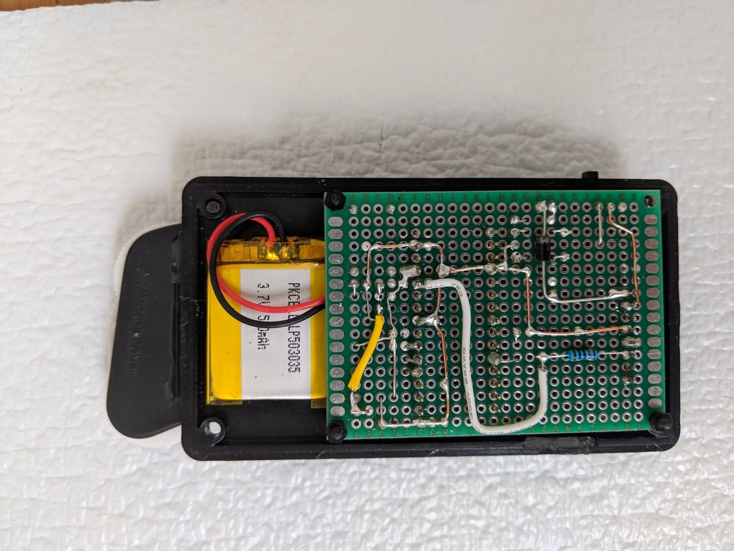
Optical balk-alert prototypeA discreet alert from the receiverThe umpire's receiver and its internal hardware, including a small rechargeable battery. I recall using a vibration motor to provide a discreet alert when the optical detector reported an interruption.
Contract work
Optical balk-alert prototypeInside the umpire's receiverA closer view of the receiver electronics. This was the portable half of the system, handling the radio message from the optical unit and producing the local alert.
Contract work
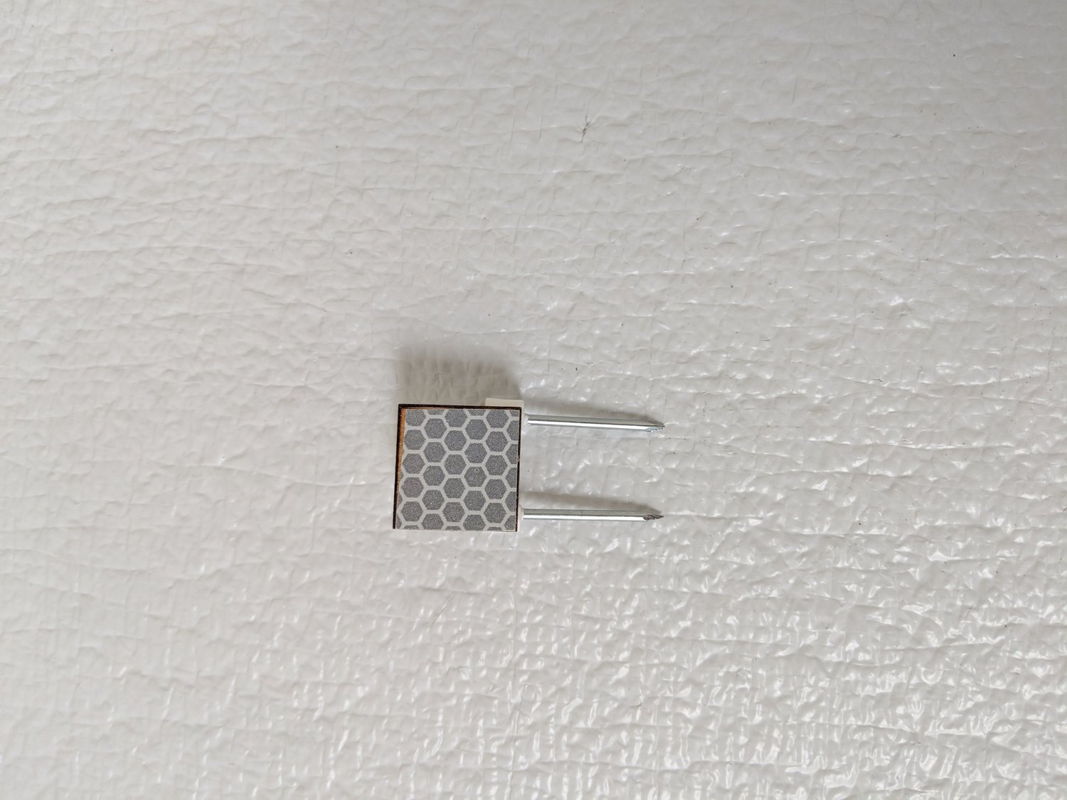
Optical balk-alert prototypeA reflector to strengthen the returning signalA small prismatic reflector with stakes for positioning it in the ground. During testing, I found that adding this retroreflector substantially improved the light returning to the detector's lens. It became a useful part of the optical arrangement.
Contract work
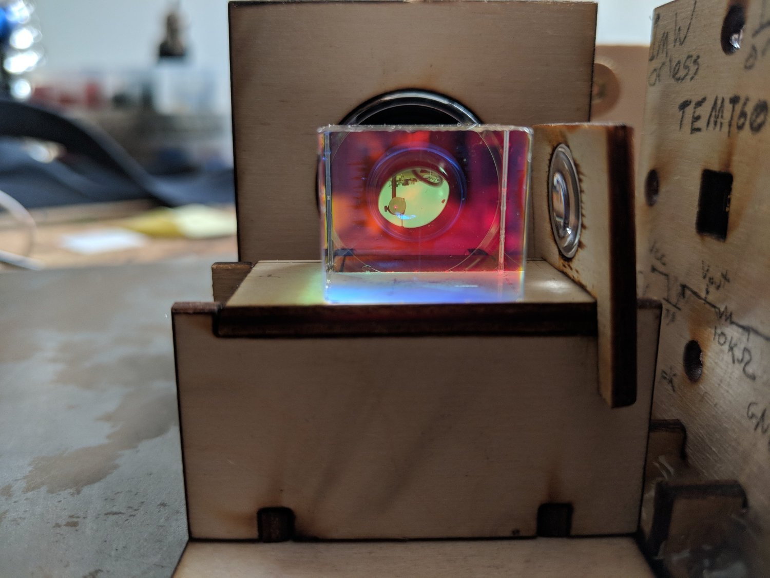
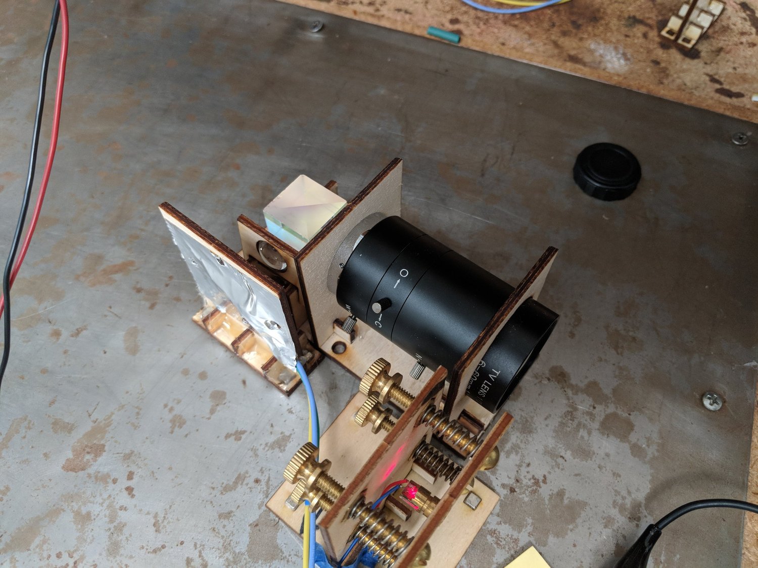
Optical balk-alert prototypeAn early color-filtering receiver conceptAn early optical arrangement intended to select the red laser light while rejecting other wavelengths. It combined a collecting lens, a dichroic element that separates light by color, and a smaller lens directing the selected light toward a sensor. I was exploring optical filtering as another way to distinguish the signal from daylight.
Contract work
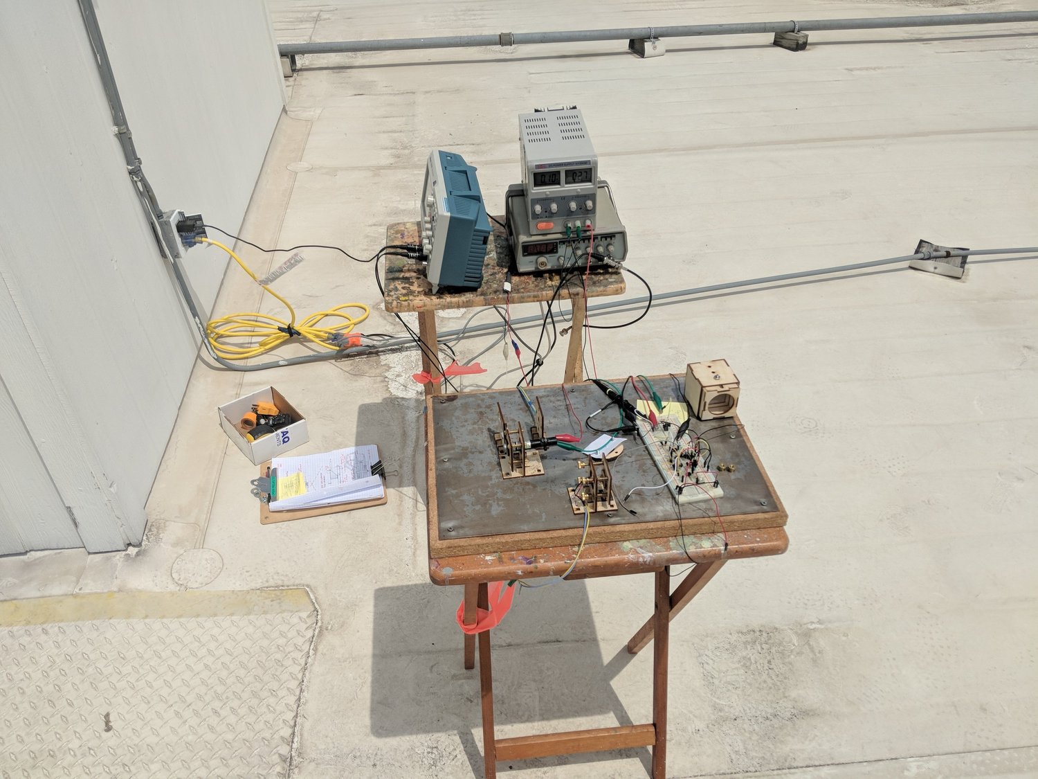
Optical balk-alert prototypeOutdoor testing on the studio roofTesting the detector on the roof at Sawyer Yards in Houston, where I had a studio. The open space let me try different distances in bright sunlight—useful conditions for checking the optical system. I was grateful to have that space available while developing the project.
Contract work
Optical balk-alert prototypeAnother view of the dichroic prototypeAnother view of the early receiver optics, using a dichroic element to direct selected colors toward the light sensor. I ultimately left this arrangement out of the later design, but it was a useful avenue to explore while developing the detector.
Contract work
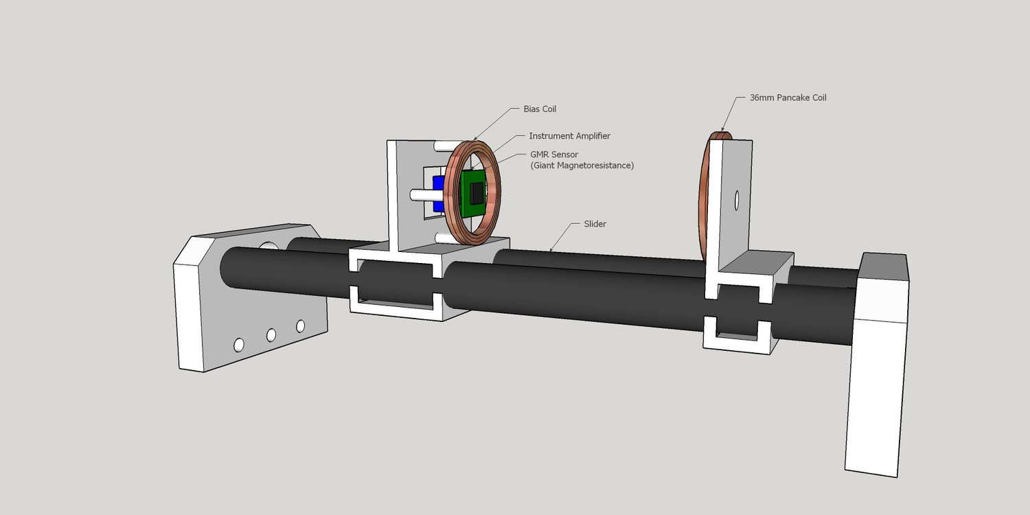
Magnetic-field measurement rigA model for an adjustable magnetic-field measurement rigA 3D model I made for a physician client's magnetic-pulse research. A sliding fixture adjusted the separation between a flat pancake coil and a magnetic-field sensor, labeled GMR in the model. A second coil around the sensor was intended to adjust the background magnetic field, with an amplifier included for reading the sensor signal. The rig was designed to help characterize the field produced by the experimental coil.
Contract work
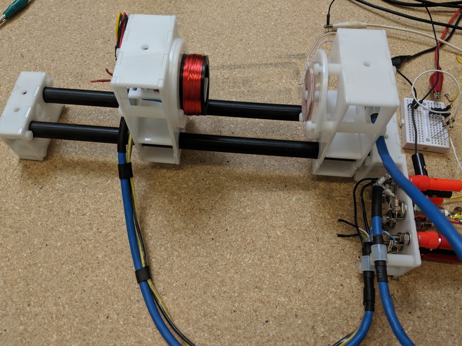
Magnetic-field measurement rigMagnetic-field test rig, built from the CAD modelI built this rig for a client who wanted to characterize magnetic pulses. The finished assembly stayed close to my CAD model: a flat coil produced the field, while an adjustable sensor mount let me change where I measured it. A separate coil provided a way to adjust the background magnetic field during testing.
Contract work
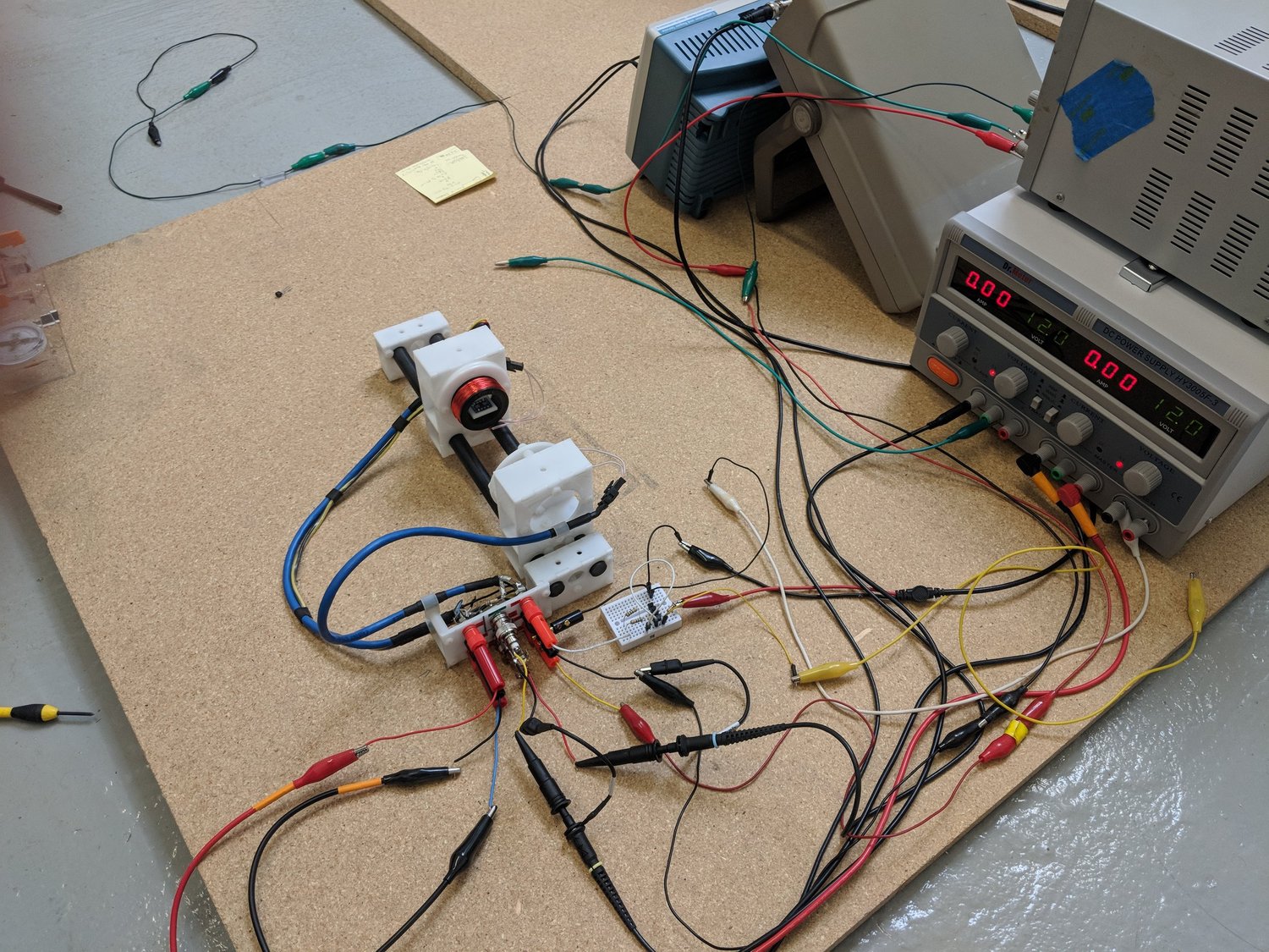
Magnetic-field measurement rigTesting the coil and magnetic sensorI applied a test signal to the coil and watched the magnetic sensor’s response on an oscilloscope. I recall using a pulsed or square-wave signal, although I would need my original notes to confirm the waveform. In retrospect, I would consider a Helmholtz coil arrangement for a more uniform test field; this single-coil setup was enough for the experiments I was doing at the time.
Contract work
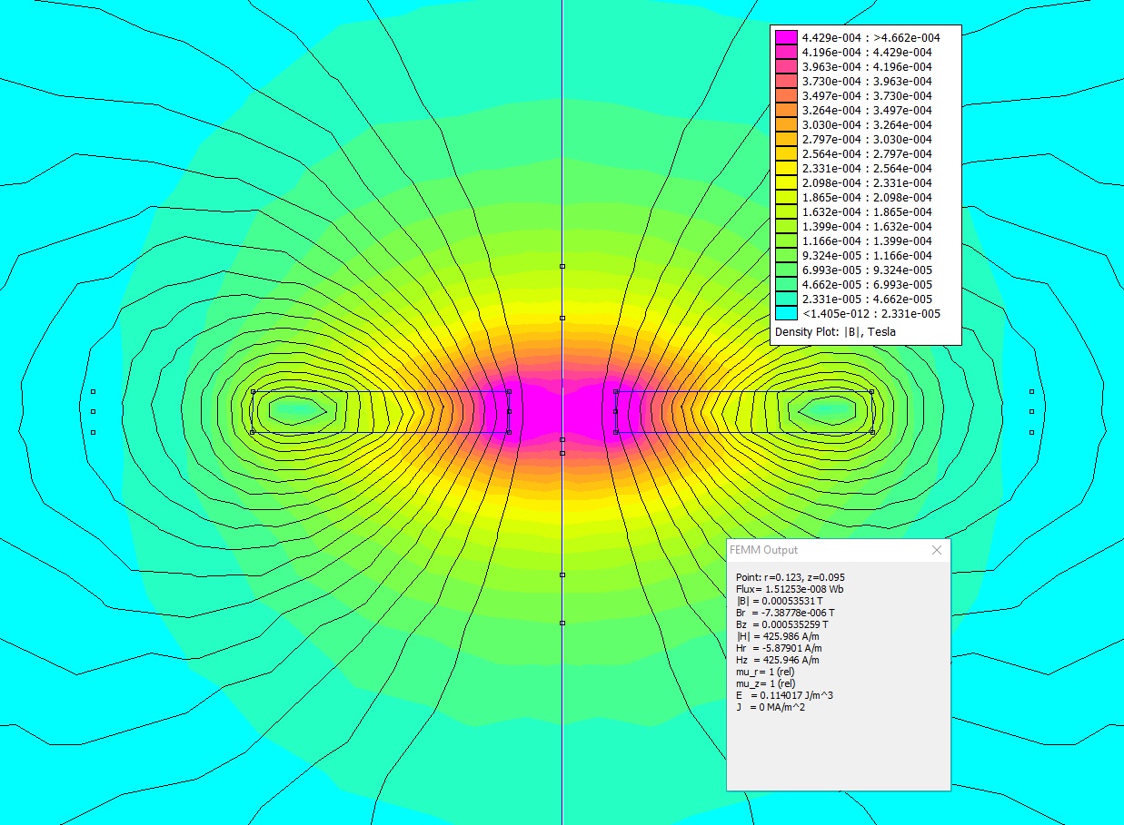
Magnetic-field measurement rigSimulating the magnetic field in FEMMI used FEMM, a finite-element simulation program, to estimate how the magnetic field would be distributed around the coil. The field lines and color map helped me compare the geometry with the region I wanted to measure. This is a simulation result, rather than a measured field map.
Contract work
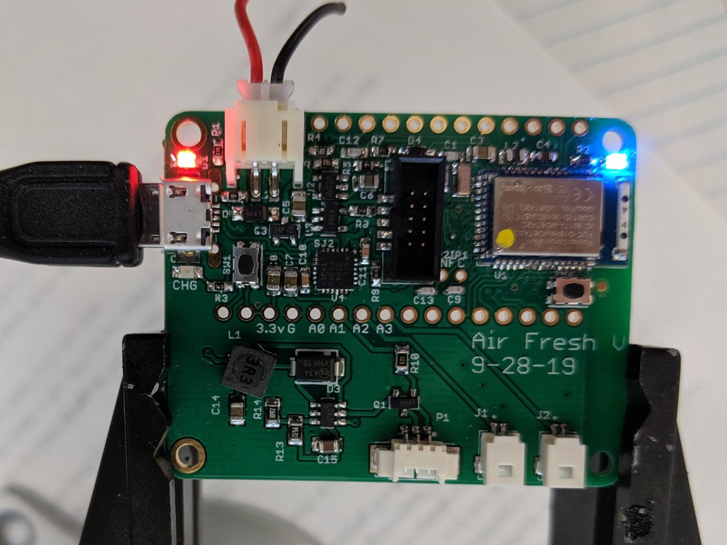
App-connected air-freshener controllerApp-controlled air-freshener prototype, powered over USBA client wanted a small, discreet air freshener controlled through a phone app. This view shows the prototype’s compact controller powered on through USB. As I recall, I adapted an Adafruit-based design and added power-related components; I would need to revisit the circuit to confirm the battery and charging details.
Contract work
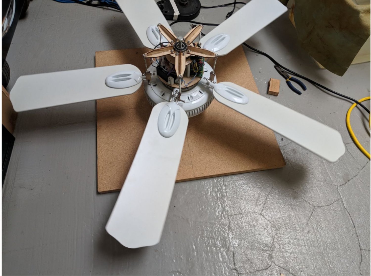
Remote-controlled adjustable-pitch fanRemote-controlled fan with adjustable blade pitchI built a fan whose blade angle could change while the hub rotated. A star-shaped linkage moved up and down, turning the blades through custom aluminum pivots. A separate wooden handheld remote controlled blade pitch, speed, and on/off operation. The mechanism worked, but a slightly off-center hub introduced some wobble; improving that alignment would be a priority in another version.
Contract work
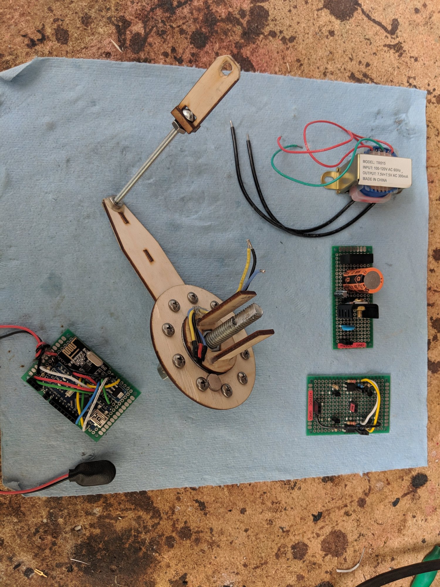
Remote-controlled adjustable-pitch fanFan power and remote-control electronicsThese are some of the power and remote-control components used in the adjustable-pitch fan. The handheld controller let the user change both the motor speed and the blade angle, as well as turn the fan on or off.
Contract work
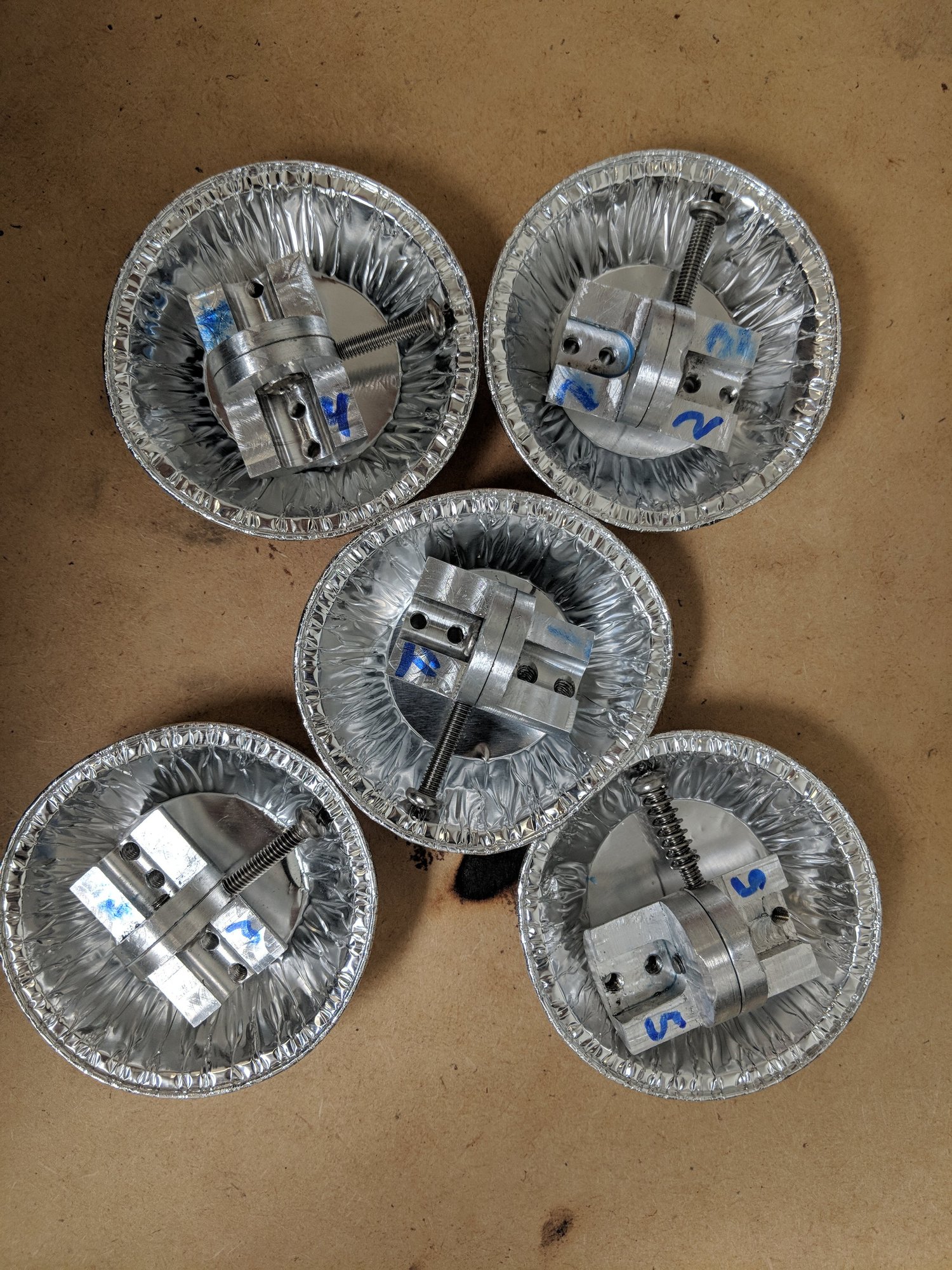
Remote-controlled adjustable-pitch fanMachined blade pivots and linkage partsI machined these aluminum parts to attach the fan blades to the rotating hub and connect them to the moving pitch-control linkage. Each part required several machining operations and tool changes. If I made another set, I would perform each operation across the whole batch before changing tools, instead of completing the parts one at a time.
Contract work
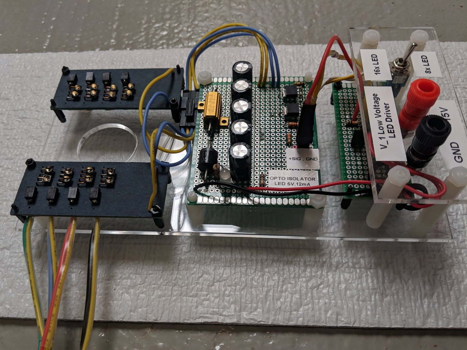
Infrared flash illuminatorCapacitor-driven infrared flash prototypeA client wanted a short, bright infrared flash to illuminate a broad area. I built a driver that stored energy in capacitors and delivered brief pulses to an array of infrared LEDs. This photo shows the prototype’s driver electronics and emitter assemblies.
Contract work
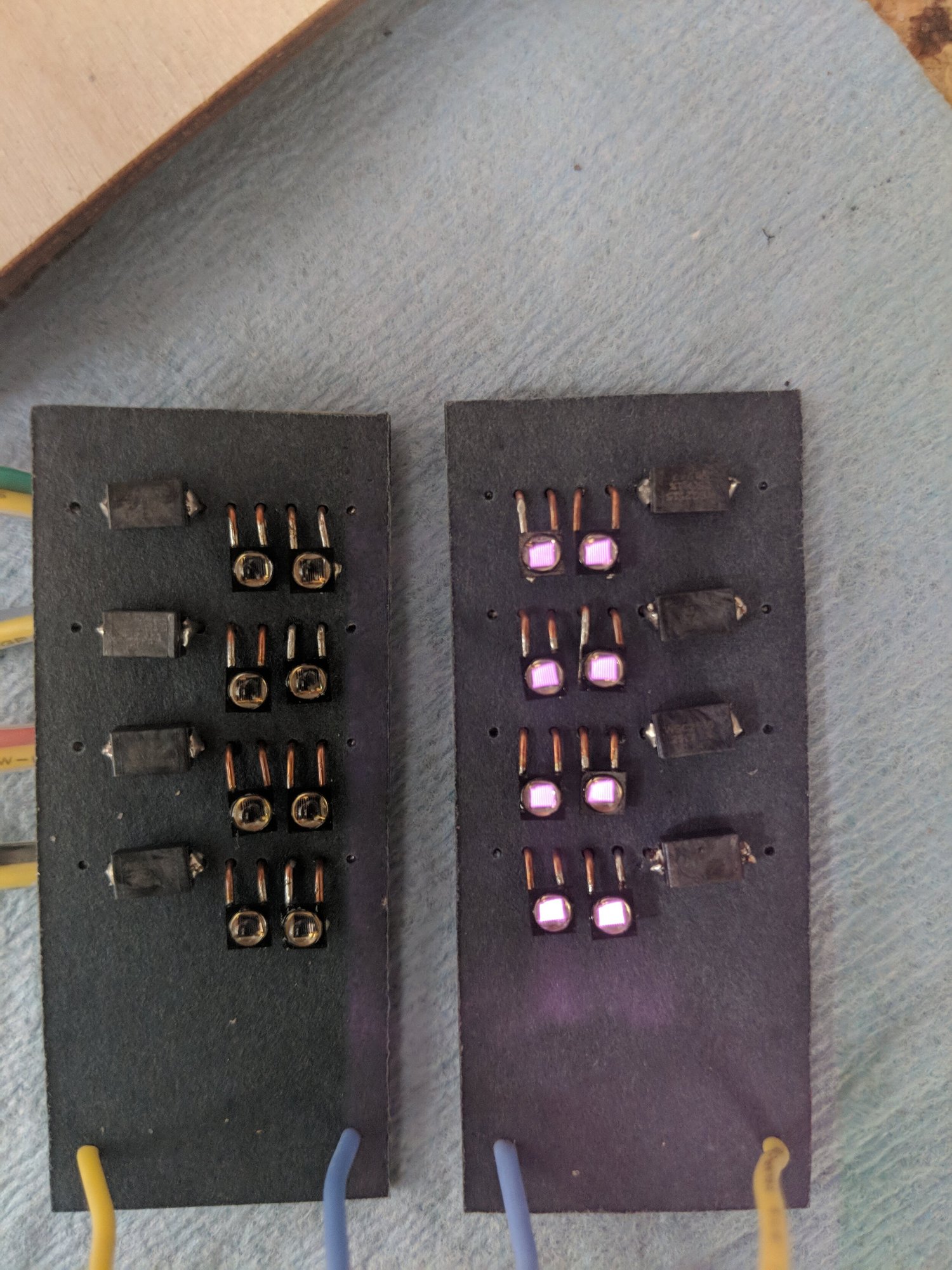
Infrared flash illuminatorInfrared LED emitter arrayThese are the infrared emitters for the flash prototype. I do not recall their exact wavelength. In a revised version, I would mount the LEDs to an aluminum heat sink to give the assembly better thermal durability, even though the intended operation used brief, infrequent pulses.
Contract work
Outlet power-loss detectorOutlet faceplate power-loss detectorA client wanted a power-loss detector that would fit neatly around an outlet faceplate. I built this prototype with a status indicator and a separate signal connection. I would need to revisit the circuit to confirm how it stored or reported a loss-of-power event; I no longer remember the exact relay or memory arrangement.
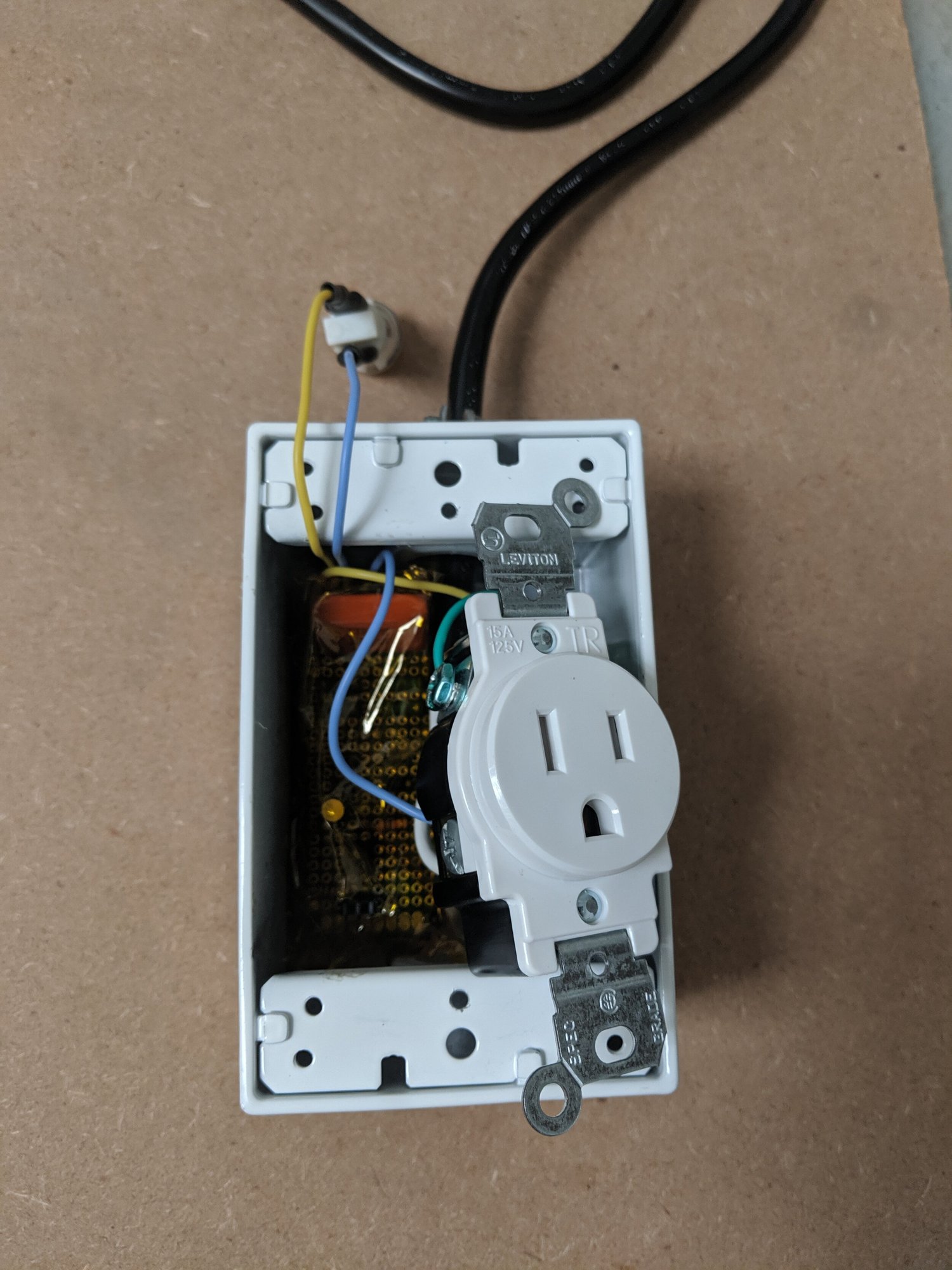
Contract work
Outlet power-loss detectorInside the power-loss detectorAn internal view of the outlet power-loss detector shows how I packaged the circuit behind the faceplate-style enclosure. The goal was to combine a visible status indication with an output that could report the event to another device.
Contract work
Stepper-motor measurement fixtureAssembling a rigid fixture for stepper-motor measurementsA client wanted to see how small a movement they could obtain from a stepper motor. I milled this housing to hold the motor, worm gear, and supporting parts rigidly while observing the output movement from individual steps. This view shows how the assembly fits together. The construction was probably more substantial than the experiment needed, but minimizing unwanted movement was my main concern.
Contract work
Stepper-motor measurement fixtureMaking small angular steps easier to seeI attached a long arm to the gear’s output so that a small angular movement produced a more visible displacement at the end of the arm. It gave the client a straightforward way to observe the movement from each step of the motor.
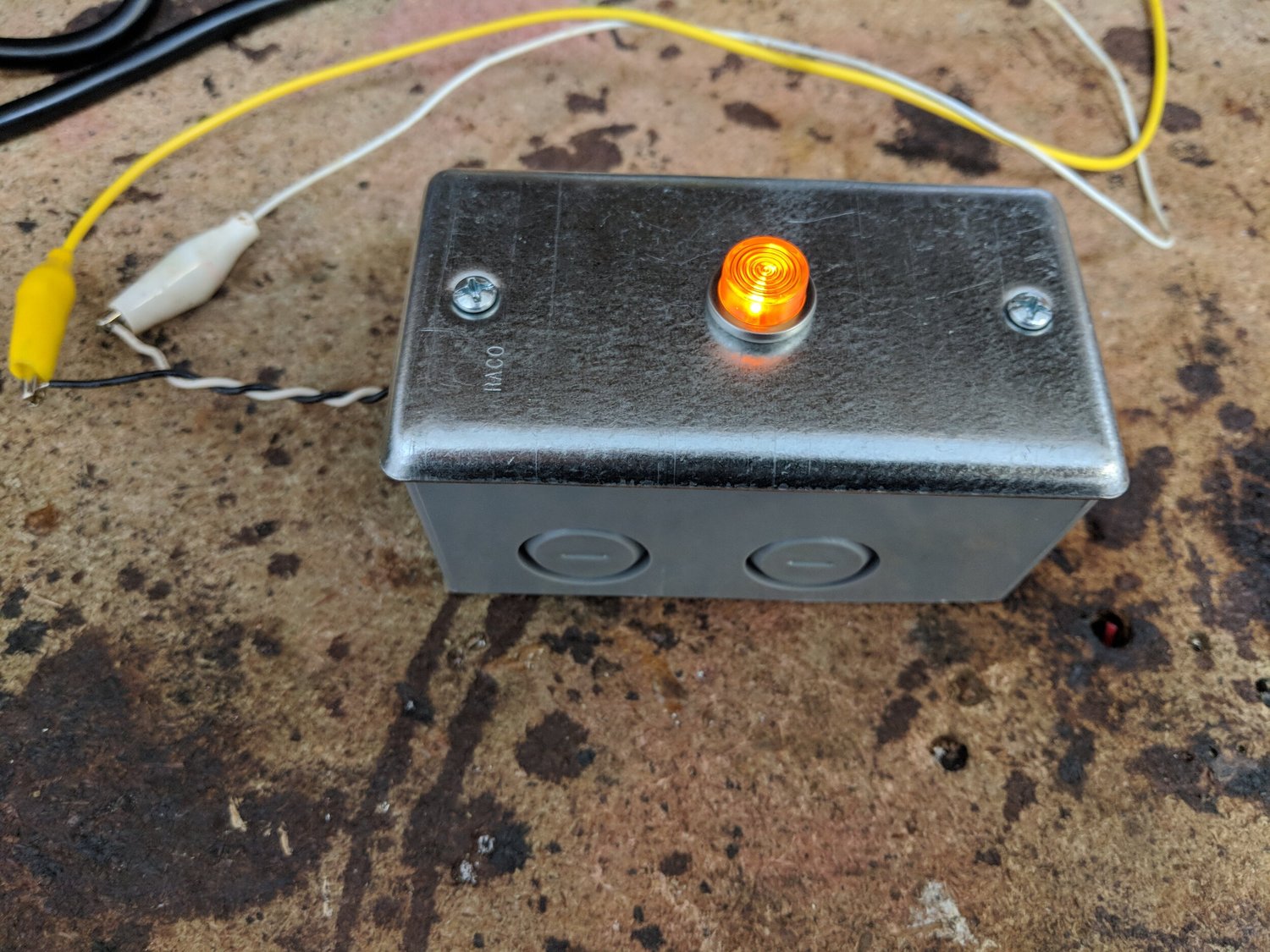
Contract work
Neon indicatorNeon indicator for two AC supply voltagesA client needed a compact neon indicator that would work on both 120-volt and 220–240-volt AC supplies. This was my first project using current-limiting diodes to regulate the lamp current. The prototype gave a similar apparent brightness at the two supply voltages I tested.
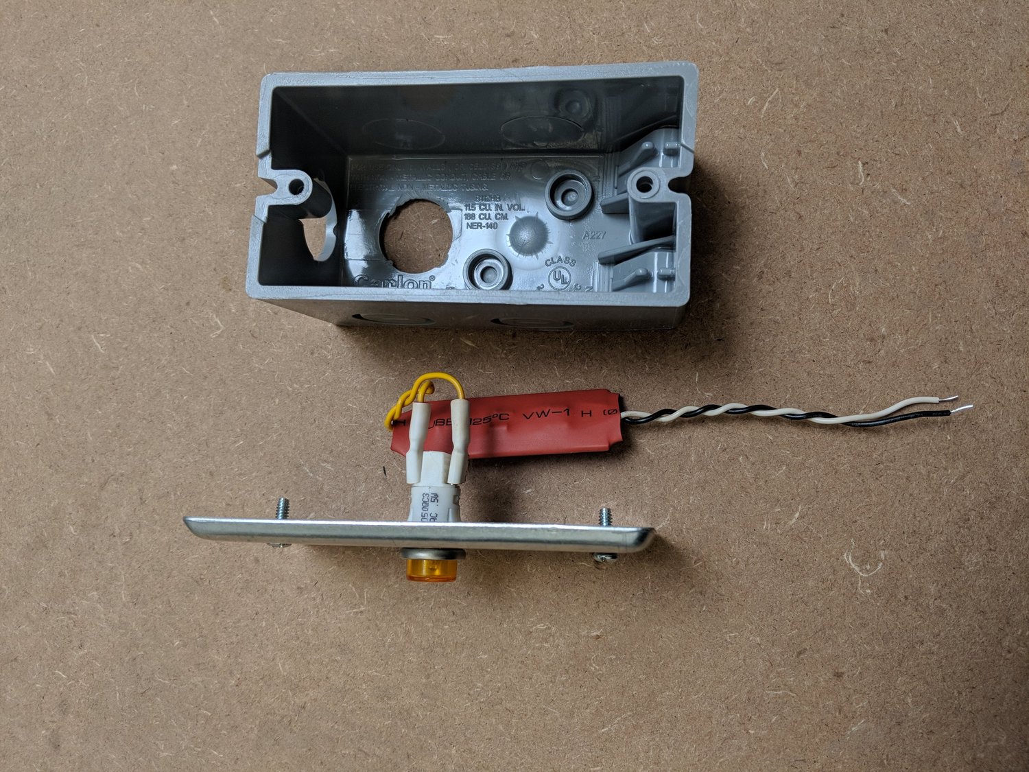
Contract work
Neon indicatorCompact neon-indicator packageA closer view of the slim indicator assembly. Keeping the current-regulating circuit and neon lamp in a small package was an important part of this client’s requirements.
Contract work
Neon indicatorComparing the indicator at 120 and 240 voltsI tested the indicators side by side on 120-volt and 240-volt AC supplies. The lamps appeared similar in brightness, which was the behavior I wanted from the current-regulating circuit. This photograph records the comparison rather than a calibrated light-output measurement.